

Instruction Manual and
Experiment Guide for
the PASCO scientific
Model PK-9023
EQUIPOTENTIAL AND
FIELD MAPPER
Instructional Manual and
Experiment Guide for the
PASCO scientific Model
PK-9023
FIELD MAPPER
012-04346B
05/91
anual and
uide for the
odel
ent G
Instructional M
scientific M
xperim
O
E
PASC
K-9023
P
FIELD MAPPER
A
S
U
1
1
0
-9
1
6
6
5
9
A
0
, C
4
0
2
ville
-
e
3
s
8
o
-3
0
1
9
X
W
• R
T
1
•
1
0
9
1
5
6
0
x
scientific
9
o
-8
6
. B
8
. O
) 7
6
1
(9
X
• P
FA
.
lvd
•
ills B
0
0
th
8
o
o
-3
6
F
8
1
0
7
)
1
6
0
1
1
(9
e
n
o
h
P
scientific
10101 Foothills Blvd. • P. O. Box 619011 • Roseville, CA 95661-9011 USA
Phone (916) 786-3800 • FAX (916) 786-8905 • TWX 910-383-2040
Copyright © October 1990 $5.00


Table of Contents
Section Page
Copyright, Warranty, and Equipment Return................................................... ii
Introduction ...................................................................................................... 1
Equipment......................................................................................................... 1
Equipment Setup............................................................................................... 2
Experiments
Parallel Plate Capacitor ........................................................................ 4
Point Source and Guard Ring ............................................................... 4
Dipoles of Opposite Charge ................................................................. 5
012-04346B
Dipoles of Like Charge......................................................................... 5
Floating Electrode................................................................................. 6
Floating Insulator.................................................................................. 6
Line and Circular Source...................................................................... 7
Line and "Sharp" Point ......................................................................... 7
Triode.................................................................................................... 8
Fluid Mechanism .................................................................................. 8
Appendix: Silver conductive ink Material Safety Data Sheet.......................... 9
i
scientific
012-04346B
Copyright and Warranty
Please—Feel free to duplicate this manual
subject to the copyright restrictions below.
Copyright Notice
The PASCO scientific Model PK-9023 Equipotential and
Field Mapper manual is copyrighted and all rights reserved.
However, permission is granted to non-profit educational
institutions for reproduction of any part of this manual
providing the reproductions are used only for their laboratories and are not sold for profit. Reproduction under any
other circumstances, without the written consent of PASCO
scientific, is prohibited.
Limited Warranty
PASCO scientific warrants this product to be free from
defects in materials and workmanship for a period of one
year from the date of shipment to the customer. PASCO
will repair or replace, at its option, any part of the product
which is deemed to be defective in material or workmanship. This warranty does not cover damage to the product
caused by abuse or improper use. Determination of whether
a product failure is the result of a manufacturing defect or
improper use by the customer shall be made solely by
PASCO scientific. Responsibility for the return of equipment for warranty repair belongs to the customer. Equipment must be properly packed to prevent damage and
shipped postage or freight prepaid. (Damage caused by
improper packing of the equipment for return shipment will
not be covered by the warranty.) Shipping costs for
returning the equipment, after repair, will be paid by
PASCO scientific.
Equipment Return
Should this product have to be returned to PASCO scientific,
for whatever reason, notify PASCO scientific by letter or
phone BEFORE returning the product. Upon notification,
the return authorization and shipping instructions will be
promptly issued.
NOTE: NO EQUIPMENT WILL BE ACCEPTED
FOR RETURN WITHOUT AN AUTHORIZATION.
When returning equipment for repair, the units must be
packed properly. Carriers will not accept responsibility for
damage caused by improper packing. To be certain the unit
scientific
will not be damaged in shipment, observe the following
rules:
1. The carton must be strong enough for the item shipped.
2. Make certain there is at least two inches of packing
material between any point on the apparatus and the
inside walls of the carton.
3. Make certain that the packing material can not shift in
the box, or become compressed, thus letting the
instrument come in contact with the edge of the box.
ii

012-04346B
Introduction
The PASCO scientific MODEL PK-9023 Field Mapper
consists of two basic elements. The first is a carbon impregnated paper in the resistance range of 5 KΩ to 20 KΩ per
square. This paper forms the conducting medium or space
between the electrodes. The second element is a conductive
ink dispensed from a pen. The ink is produced from silver
particles in a suspension liquid. As the ink dries, the silver
flakes settle on top of each other forming a conductive path,
(or conductive ink electrodes). The resistance of the ink is
between .03 and .05 Ω/cm for a 1 mm wide line.
Because the paper has a finite resistance, a current must flow
through it to produce a potential difference. This current is
supplied by the conductive ink electrodes which causes a
potential drop to occur across the paths. Because of the
large difference between the ink’s resistance and the
resistance of the paper, this potential drop is less than 1% of
that produced across the paper. Therefore, for all practical
purposes the potential drop across the electrodes may be
considered negligible.
-
+
Equipotential and Field Lines
It would be desirable that the potential measuring instrument
have an infinite impedance. An electrometer such as the
PASCO Model ES-9054B would be optimal, however, a
standard electronic voltmeter such as PASCO's SE-9589
Handheld Digital Multimeter with a 10 MΩ (or higher) input
impedance is sufficient. Since this impedance is at least 100
times greater than that of the paper, the greatest distortion of
the field which can be produced by the voltmeter is approximately 1%.
Instructional Manual and
Experiment Guide for the
PASCO scientific Model
PK-9023
FIELD MAPPER
d
n
l a
a
e
u
n
r th
a
fo
l
l M
e
e
a
id
d
n
u
o
tio
c
M
t G
n
tru
e
tific
s
n
im
In
r
ie
e
c
p
s
x
O
E
C
S
3
2
PA
0
9
K
P
FIELD MAPPER
A
S
U
1
1
0
9
1
6
6
5
9
A
C
0
,
4
e
ll
0
i
2
v
-
e
3
s
8
o
3
-
R
0
1
9
tific
X
W
•
T
n
•
1
1
0
9
1
5
6
0
x
scie
9
o
8
B
6
.
8
O
7
.
)
P
6
1
9
(
X
•
A
F
.
d
•
lv
B
s
ll
i
0
h
0
t
8
o
3
o
-
F
6
8
1
7
0
)
1
6
0
1
1
9
(
e
n
o
h
P
scientific
10101 Foothills Blvd. • P. O. Box 619011 • Roseville, CA 95661-9011 USA
Phone (916) 786-3800 • FAX (916) 786-8905 • TWX 910-383-2040
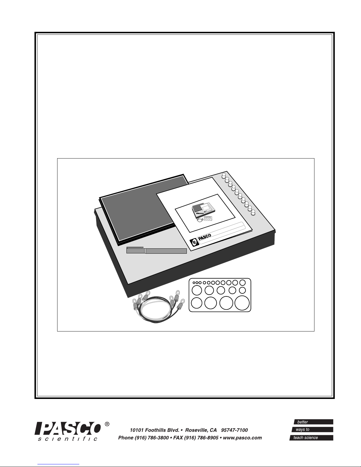
Equipment
The PK-9023 Field Mapper includes:
• 100 sheets of conductive paper with 23 x 30 cm grid
• a silver conductive ink pen for approximately 200 ft of
continuous line
• a corkboard working surface
• 10 push pins for attaching the paper to the board
• 3 wires for connecting the conductive paths
• a circle template for drawing the conductive paths.
• a large plastic tray for storing the paper and other
supplies
• Instruction manual and experiment guide.
The following supplies can be ordered separately
from PASCO scientific
Conductive ink pen Model No. PK-9031B
100 sheets of 23 x 30 cm conductive paper with cm grid
Model No. PK-9025A
100 sheets of 30 x 46 cm conductive paper (without grid)
Model No. PK-9026A
scientific
1

Equipment Setup
IMPORTANT:
The silver conductive ink reaches its maximum
conductivity after 20 minutes drying time. For
optimal results plan the timetable for conducting the
experiments and correlate drawing the conductive
ink paths accordingly.
1. Plan and sketch the layout (size, shape and relative
spacing) of the charged paths to be studied on a piece of
scratch paper. These paths can be any two dimensional
shape, such as straight or curved lines, circles, dots,
squares, etc. Since the charged paths will actually be
conductive ink electrodes, they will be referred to as
electrodes.
2. Draw the electrodes on the black paper (see Figure 1).
NOTE: This is the most difficult and crucial part
of the experiment. Follow these steps carefully.
a. Place the conductive paper, printed side up, on a
smooth hard surface. DO NOT attempt to draw the
electrodes while the paper is on the corkboard.
b. Shake the conductive ink pen (with the cap on)
vigorously for 10-20 seconds to disperse any
particle matter suspended in the ink.
012-04346B
Figure 1
e. A plastic template is included with the PASCO
scientific Field Mapper, for drawing circles. (see
Figure 3) Place the template on the conductive
paper and draw the circles with the conductive ink
pen. (If desired, you may first draw the circle
template with a soft lead pencil and trace over the
pencil line with the ink.)
c. Remove the cap. Pressing the spring loaded tip
lightly down on a piece of scrap paper while
squeezing the pen barrel firmly starts the ink
flowing. Drawing the pen slowly across the paper
produces a solid line. Drawing speed and exerted
pressure determines the path width. (see Figure 2)
Figure 2
d. Once a satisfactory line is produced on the scrap
paper, draw the electrodes on the black conductive
paper. If the line becomes thin or spotty, draw
over it again. A solid line is essential for good
measurements.
The line will be air dry in 3-5 minutes at room
temperature. However, the medium won’t reach
maximum conductivity until after 20 minutes
drying time.
Figure 3
3. Mount the conductive paper on the corkboard using one
of the metal push pins in each corner.
2
scientific
 Loading...