

Page 1
®
Instruction Manual
012-12695A
*012-12595*
DC Programmable Power Supply
PI-9880
Page 2

®
DC Programmable Power Supply 012-12695A
2
Page 3

®
Model No. PI-9880 012-12695A
3
Page 4

DC Power Supply Table of Contents
Contents
Introduction . . . . . . . . . . . . . . . . . . . . . . . . . . . . . . . . . . . . . . . . . . . . . . . . . . . . . . . . . . . 3
Typical Uses . . . . . . . . . . . . . . . . . . . . . . . . . . . . . . . . . . . . . . . . . . . . . . . . . . . . . . . . . .4
Specifications. . . . . . . . . . . . . . . . . . . . . . . . . . . . . . . . . . . . . . . . . . . . . . . . . . . . . . . . . .4
Tutorial. . . . . . . . . . . . . . . . . . . . . . . . . . . . . . . . . . . . . . . . . . . . . . . . . . . . . . . . . . . . . . . 7
Basic Operation . . . . . . . . . . . . . . . . . . . . . . . . . . . . . . . . . . . . . . . . . . . . . . . . . . . . . . . 19
Standard Functions (Rectangle, Ramp, and Stair) . . . . . . . . . . . . . . . . . . . . . . . . . . . . 22
Custom Program . . . . . . . . . . . . . . . . . . . . . . . . . . . . . . . . . . . . . . . . . . . . . . . . . . . . . . 28
Technical Support . . . . . . . . . . . . . . . . . . . . . . . . . . . . . . . . . . . . . . . . . . . . . . . . . . . . . 35
Page 5
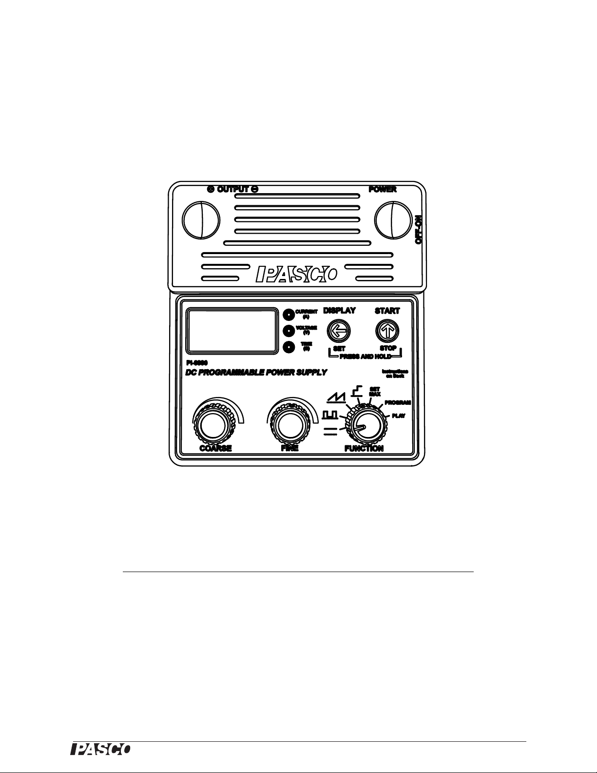
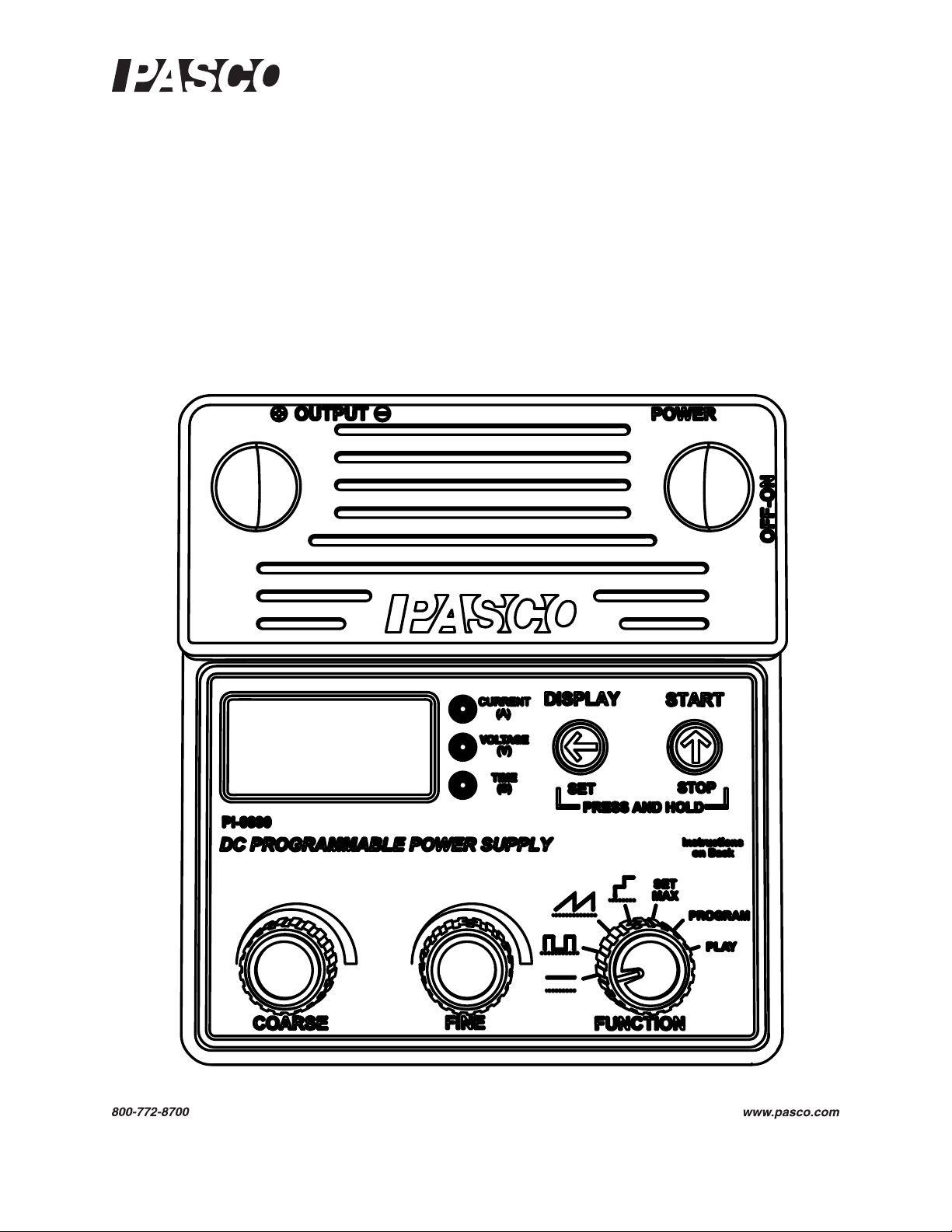
DC Programmable Power Supply
®
PI-9880
Included Equipment Part Number
DC Programmable Power Supply PI-9880
AC Power Adapter (100 - 240 VAC, 24 VDC) 540-102
Introduction
The PI-9880 DC Programmabl e Power Supply sources 0–18 volts (V) at up to 1 ampere (A). You can use the
Power Supply as a simple constant-voltage source, or take advantage of its advanced features to output periodic
functions and custom programs.
5
Page 6
®
DC Programmable Power Supply 012-12695A Typical Uses
Typical Uses
The Programmable Power Supply works well with a variety of electronic circuits,
motors, lamps, heaters, and Peltier devices, and the PASCO apparatus listed below.
Model Number Name Comments
ET-8499 Calorimeter Set the Power Supply’s Stair function for a single heat pulse (see
EM-8678 Charge/Discharge Circuit Use the Power Supply to charge the circuit’s capacitor or battery. Set the
ET-8782 Thermoelectric Circuit Set the Power Supply’s maximum voltage to 10 V (see page 20).
ME-8088 Centripetal Force
Apparatus
ME-8750 Mechanical Oscillator
Driver
ME-8955 Rotational Motor Drive Drive the Rotating Platform (ME-8951) with the Magnetic Levitation
TD-8513 Heat Conduction Apparatus Power the apparatus with a positive-offset rectangle wave (see page 22)
page 26).
Power Supply’s maximum voltage to 5 V (see page 20).
Use the Power Supply’s ramp function (see page 23) to slowly increase
the rotational speed.
Drive dynamics carts (such as ME-6950) or the Chaos/Driven Harmonic
Accessory (CI-6689A).
Accessory (EM-8947) or Rotational Acceleration Tank (ME-8957).
or sine wave (the Power Supply’s default custom program, see page 28).
Specifications
General Specifications
Output Voltage Adjustment 0–18 V
Voltage Adjust Resolution 10 mV
Voltage Adjust Accuracy 0.25% of setting or 20 mV, whichever is larger
Current-limit Shutdown Programmable, 0.010–1.050 A
Current Measurement Accuracy 3%
Load Regulation 1%
Output Noise 20 mV peak-to-peak typical, 60 mV peak-to-peak at full load
Function-specific Specifications
Function 1: Constant DC Output
(see page 19)
Function 2: Rectangle Wave
(see page 22)
Function 3: Ramp
(see page 23)
Monitor voltage or current, or cycle with adjustable time
Programmable maximum voltage
Programmable minimum voltage
Programmable period: 0.1–999 s
Programmable duty cycle: 1–99%, Jitter: ±300 μs
Monitor voltage or current
Programmable maximum voltage
Programmable minimum voltage
Programmable period: 0.1–999 s
Programmable ramp direction (ascending or descending)
Alternating ramp direction option (triangle wave)
Programmable number of cycles: 1 to 999, or infinite
Monitor voltage or current
6
Page 7
®
Model No. PI-9880 Specifications
Function 4: Stair
(see page 25)
Function 5: SET MAX
(see page 20)
Function 6: PROGRAM
Custom program entry
(see page 28)
Function 7: PLAY
Custom program output
(see page 29)
Programmable maximum voltage
Programmable step voltage: 0.01–18.00 V
Programmable minimum voltage
Programmable step time: 0.1–999 s
Programmable stair direction (ascending or descending)
Alternating stair direction option
Programmable number of cycles: 1 to 999, or infinite
Monitor voltage or current
Programmable voltage limit: 0.01–18.00 V
Programmable maximum current: 0.010–1.050 A
Automatic shutdown timer: 0.01–99.99 hours
“Hidden” Global Maximum voltage: 0.01–18.00 V (remembered after power off)
3–99 programmable voltage points (remembered after power off)
Edit modes: append, insert, delete point, delete entire program
Programmable scale factor: 1–100% of programmed voltage
Programmable step-time: 0.1–999 s
Step-style and vector-style options
Programmable play direction (forward or backward)
Alternating play direction option
Programmable number of cycles: 1 to 999, or infinite
Monitor voltage or current
Combining Two Units Two or more Programmable Power Supplies can be connected in series. Connect the negative terminal of one unit to the positiv e termin al of
the other .
Excessive voltage levels can be achieved when combining units in this way; students
should do so only under the supervision of a qualified instructor.
Storage For easy storage of multiple units, indentations in the Programmable
Power Supply accept the feet of an identical unit stacked on top of it.
7
Page 8
®
DC Programmable Power Supply 012-12695A Specifications
Power
Supply
+
-
100 mF
100 W
100 mF
100 W
Power
Supply
+
-
20 W
Experiment-design Considerations Please note the following properties of
the Programmable Power Supply when planning an application:
• The Power Supply is over-current protected, but it is not current-limited or
current-regulated. If the maximum output current (1 amp by default, or lower if
you have changed the maximum-current setting) is exceeded, the Power Supply
will need to be manually reset before operation can resume. See “Over-current”
on page 20.
• The output voltage range is 0 to 18 V. To achieve a negative voltage switch the
positive and negative leads.
• This device is a programmable power source, not a function generator. The maximum frequency of the rectangle and ramp functions is 10 Hz. The maximum frequency of the default sine-wave custom program is about 0.1 Hz.
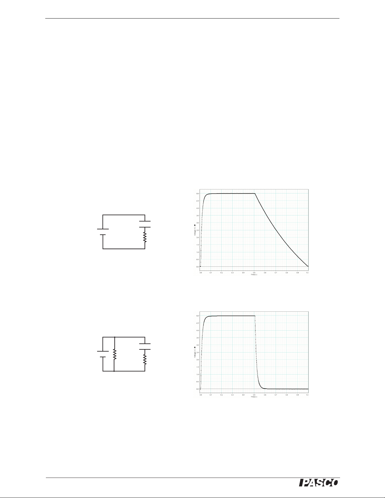
• The Power Supply is designed for current flow in one direction: out of the positive terminal and into the negative terminal. In the example illustrated below, the
Power Supply is switched from 0 V to 5 V, then back to 0V. The capacitor does
not discharge in a predictable way because there is not a simple path to ground.
To provide a path to ground, connect a resistor across the Power Supply’s
terminals as shown.
A current-sinking resistor is not typically required when driving motors, lamps
and heating resistors since these devices have a low DC resistance.
8
Page 9
®
Tutorial
This tutorial will introduce you to the DC Programmable Power Supply. As you follow the steps, it will
be helpful to measure and view the Power Supply’s voltage output. Here are three possible ways to do
that:
1. Use a data-acquisition program such as DataStudio with a voltage s ensor. The sample waveforms
shown in the tutorial were collected in this manner.
2. Use an digital storage oscilloscope capable of displaying several second ’s worth of data.
3. Use a normal volt meter. This option will not allow you to reproduce the graphs on the following
pages, but you will be able to observe the variation of the Power Supply’s output.
If possible, connect a load resistor (o r other device such as a small light bulb) to the output so that you
can look at the current draw. You can use any resistor from about 20 Ω to 100 Ω, but check the power
rating to make sure it will not overheat; during the tutorial, you will apply vol tages up to 10 volts.
Set-up
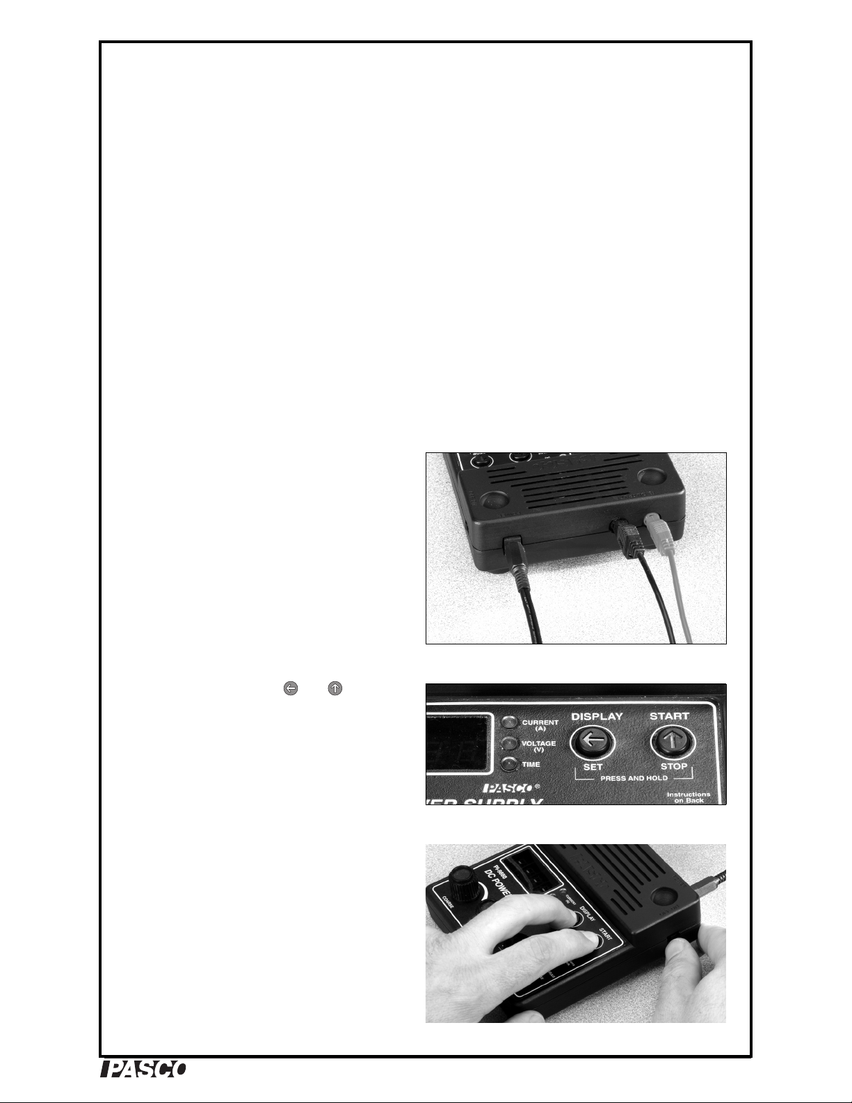
1. Plug the AC adapter into a wall outlet and
into the port labeled POWER on the Power
Supply.
2. Use a pair of banana-plug patch cords to
connect a load resistor (or other device) to
the Power Supply’s red (+) and black (−)
OUTPUT ports.
3. Connect a voltage sensor, meter, or oscilloscope to the OUTPUT ports.
4. Notice the two buttons: and . You will
use these buttons, along with the knobs, to
control the Power Supply’s output and display.
5. Push and hold both buttons. While holding
the buttons, turn on the power switch (if it is
already on, turn it off and on again). Continue to hold both buttons until the display
shows LLLL, then release the buttons. The
original factory settings have been loaded.
POWER and OUTPUT connections
Buttons
Load factory settings
9
Page 10
®
DC Programmable Power Supply
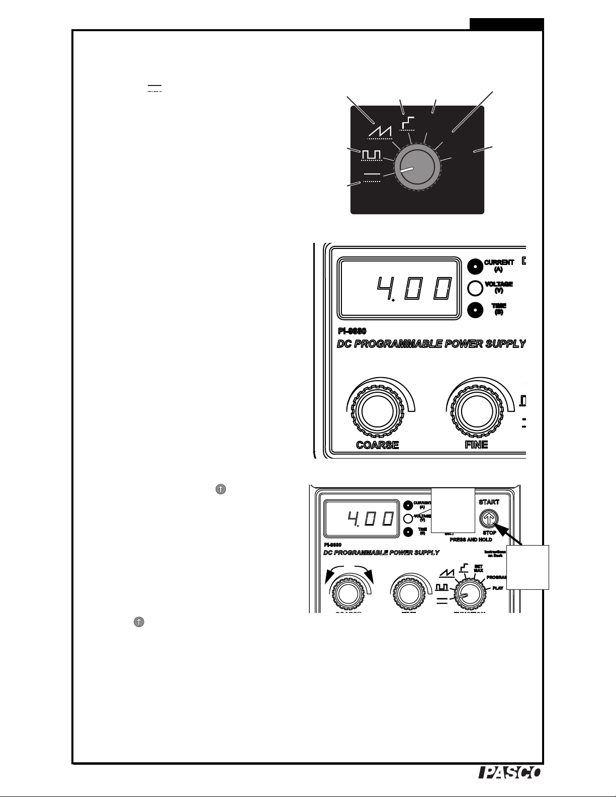
SET
MAX
PLAY
PROGRAM
FUNCTION
Constant
DC
Rectangle
Wave
Ramp
Stair
Set Maximum
Values
Enter
or Edit
Custom
Program
Play
Custom
Program
Voltage
LED blinks
rapidly.
Function 1: DC Voltage
1. Turn the Function knob to the Constant DC
position ( ). The display briefly shows F1
(for “Function 1”), then 0.00 (for zero vo lts).
The Voltage LED is lit, indicating that the
quantity displayed is voltage in units of
volts.
2. Turn the Coarse knob to set the voltage to
4.00 V. Note that the displayed voltage
reflects the actual voltage at the output terminals.
Turn the Fine knob. If you rotate it slowly,
the voltage changes by 0.01 V per detent. If
you rotate the knob more quickly, it changes
by 0.04 V per detent. Adjust the voltage back
to 4.00 V.
Tutorial
The Function knob
3. Quickly press and release to temporarily
switch off the output. The Voltage LED
blinks rapidly, and the actual output voltage
drops to zero, though the display still shows
the voltage setting.
Turn the Coarse knob. Note that you can
adjust the voltage setting while the actual
output remains zero. Return the voltage setting to 4.00 V
Press to switch the output back on. The
Voltage LED is now on steadily to indicate
that the output voltage is live.
Set voltage
Quickly
press and
release.
Temporarily switch off output
10
Page 11
®
Model No. PI-9880 012-126955A
Quickly
press and
release.
Press
and
hold.
The TIME
LED starts
blinking.
Press
and hold.
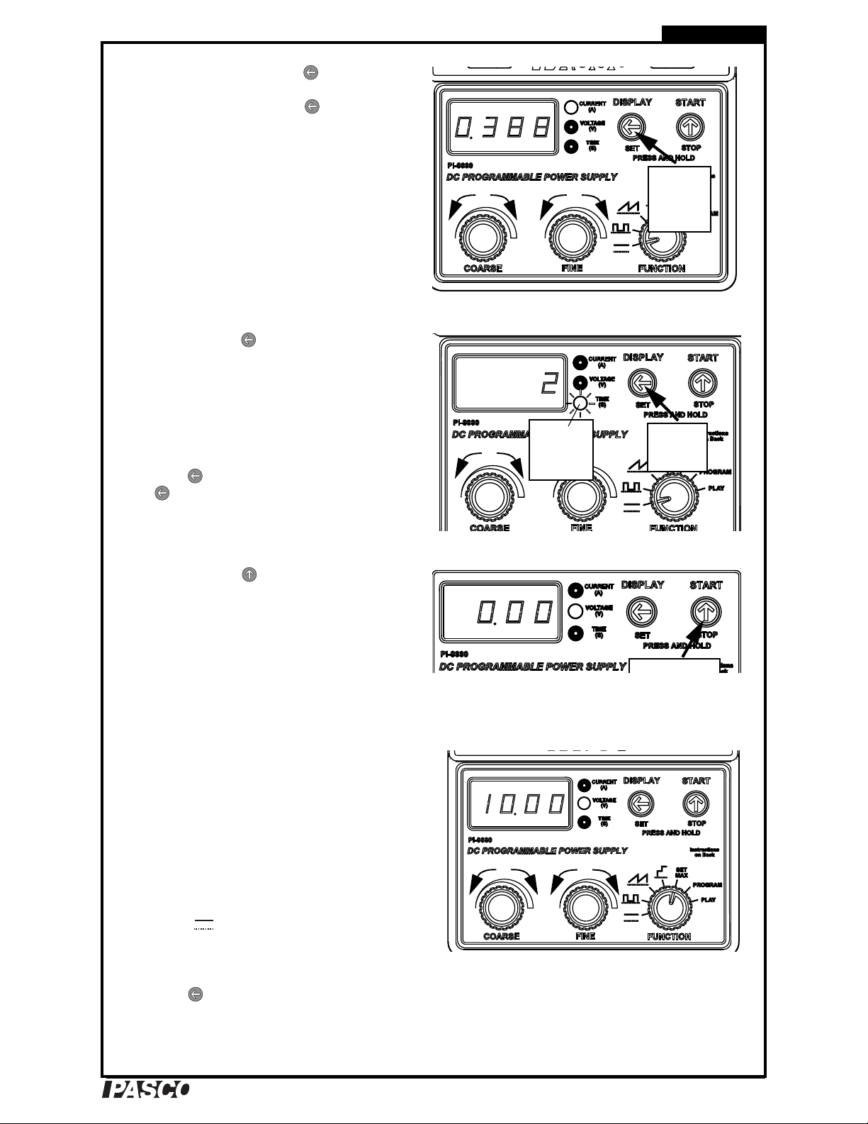
4. Quickly press and release . The Current
LED lights, and the display now shows output current in amps. Press a few times to
toggle the display between current and voltage.
While viewing current on the display, turn
the Coarse and Fine knobs. You are actually
adjusting the voltage, but you see the resulting current change on the display.
5. Press and hold until the Time LED starts
blinking, and the displa y shows 0; while
holding the button, turn the Coarse knob to
change the display to 2. Release the button.
The display now automatically toggles
between current and voltage every 2 seconds.
Tutorial
Change display
Press to pause the display toggling; press
again to resume.
6. Press and hold until the display shows
0.00. Release the button. You have just reset
the output voltage to zero and the display to
voltage.
For more information about constant DC output, see
page 19.
Function 5: SET MAX
1. Turn the Function knob to SET MAX. The
display briefly shows F5 (for “Function 5”)
followed by 18.00, which is the Power Supply’s voltage-limit setting. (Note that the
actual output voltage is zero.)
Turn the Coarse knob to set the voltage limit
to 10 V.
Set display-toggle time
Reset output and display
Turn the Function knob back to Constant DC
mode ( ). Try to adjust the output voltage
to over 10 volts.
2. Turn the Function knob back to SET MAX.
Press once to display the maximumcurrent setting. Turn the Coarse and Fine
knobs to adjust the maximum current to
0.210 A.
Set maximum voltage
11
Page 12
®
DC Programmable Power Supply
Press so
the TIME
LED starts
blinking.
Press
and
hold both
buttons.
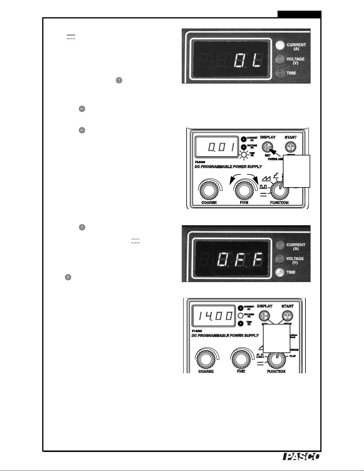
Turn the Function knob back to Constant DC
( ). Increase the voltage until the Current
LED blinks amber and the display shows
OL (for “overload”) to indicate that the maximum current has been exceeded and th e o utput has automatically turned off (this will
happen only if you h ave a load hoo ked t o the
power supply). Press to return the Power
Supply to normal operation.
Turn the Function knob back to SET MAX.
Press once to display the maximum current setting. Adjust it back to 1.05 A.
3. Press so that the Time LED starts blink-
ing and the display shows 0.00; this is the
countdown time in hours. Turn the Fine
knob to set the time for 0.01 hour (36 seconds). Note that the Time LED is blinking to
indicate that the countdown has not started
yet.
Tutorial
Display shows current Over Load
Press to start the countdown. The Time
LED is now lit steadily. Turn the Function
knob back to Constant DC ( ) and set the
voltage to 1 V. Wait for the remainder of the
36 seconds. When the countdown time has
elapsed, the display shows OFF to indicate
that the output has been switched off. Press
to return the Power Supply to normal
operation.
4. Turn the Function knob back to SET MAX.
Push and hold both buttons until the Voltage
LED starts blinking fast and the display
shows 18.00 (this is the Global Maximum
voltage setting); while holding both buttons,
turn the Coarse knob to change the Global
Maximum to 14.00 V. Release both buttons.
You have just set the Power Supply so that
the output voltage, the voltage-limit setting,
and any other voltage setting cannot exceed
14 V.
Set countdown time in hours
Display shows auto off
Setting “Hidden” Global Maximum voltage
5. Repeat the previous step to turn the Global
Maximum ba ck to 18 V.
For more information about setting maximum values,
see page 20.
12
Page 13

®
Model No. PI-9880 012-126955A
Function #2: Rectangle Wave
1. Turn the Function knob to Rectangle Wave
( ). The display briefly shows F2, then
0.00 (the rectangle wave’s maximum-voltage
setting).
2. Turn the Coarse knob to set the maximum
voltage to 6.00 V. Note that the actual output
voltage is zero (the Voltage LED blinks to
indicate that the displayed voltage is not
live).
3. Press to start running the function: a 6 V
positive squ are wave wit h a 2 s period.
Tutorial
(Note the START label printed above the
button, which indicates what happens when
you press the button.)
4. Try turning the Coarse and Fine knobs; the
knobs have no effect when the function is
running.
5. Press and hold for about 1 second to stop
running the function.
(Note the STOP label printed below the button, which indicates wh at happe ns wh en you
press and hold the button. )
6. Press and hold (SET); the Voltage LED
starts blinking fast and the display shows the
minimum-voltage setting; while holding the
button, turn the Coarse knob to adjust the
minimum voltage to 2.00 V. Release the button.
Press (START). The output voltage now
alternates between 6 V and 2 V.
Rectangle Wave
Press and hold (STOP).
Minimum voltage set to 2 V
13
Page 14

®
DC Programmable Power Supply
7. Press . The Time LED lights and the dis-
play shows the rectangle wave’s period (in
seconds). Turn the Coarse and Fine knobs to
change the period to 0.13 s. (By turning the
Fine knob slowly you can adjust the period
in 0.01 s increments.)
Turn the Coarse and Fine knobs to set the
period to 3.00 s.
Press (START). The output voltage now
completes a full cycle every 3 seconds.
Press and hold (STOP). No te th at th e di s play has gone back to showing the maximum-voltage setting.
8. Press (DISPLAY) so that the Time LED
is lit.
Press and hold (SET); the Time LED
starts blinking and the display shows 50 (for
a duty cycle of 50%); while holding the button, turn the Coarse knob to change the duty
cycle to 10%.
Tutorial
Period set to 3 s
Press (START). The output voltage now
spends 10% of the time at the maximum
voltage and 90% of the time at the minimum
voltage.
Press and hold (STOP).
For more information about the Rectangle Wave function, see page 22.
Function 3: Ramp
1. Turn the function knob to Ramp ( ). The
display briefly shows F3, then 18.00 (the
ramp’ s maximu m-vo l t age setting).
2. Set the maximum voltage to 8.00 V.
3. Press and hold (SET); the Voltage LED
starts blinking fast and the display shows the
minimum-voltage setting; while holding the
button, adjust the minimum voltage to
2.00 V.
4. Press (DISPLAY); the Time LED lights
and the display shows the ramp’s period. Set
the period to 2.00 s.
5. Press (START) to run the function and
observe the waveform.
Duty cycle of 10%
Ramp with 2 V minimum and 8 V maximum
14
Press and hold (STOP).
Page 15

®
Model No. PI-9880 012-126955A
6. Press (DISPLAY) to display the period.
Turn the Coarse knob to set the period to
–2.00 s (a negative value).
Press (START) to run the function and
observe the waveform. Note that the negative period setting makes the ramp descend.
Press and hold (STOP).
Press (DISPLAY) to display the period
again and set it back to +2.00 s.
A negative period setting causes a descending ramp
7. Press and hold (SET); the Time LED
starts blinking fast and the display shows 0
(the “auto-repeat” setting); while holding the
button, turn the Fine knob to change the
auto-repeat setting to 2.
Tutorial
Press (START) to run the function. The
output now completes two ramps and stops
automatically.
8. Press (DISPLAY) so that the Time LED
is lit. Press and hold (SET) and adjust the
auto-repeat setting to –2 (a negative value).
Press (START) to run the function and
observe the waveform. The ramp now alternates between ascending and descending to
form a triangle wave. It completes two full
cycles and stops automatically.
For more information about the Ramp function, see
page 23.
Ramp plays twice and then stops
A negative auto-repeat setting causes a triangle wave
15
Page 16

®
DC Programmable Power Supply
Function 4: Stair
1. Turn the Function knob to SET MAX. Set
the Power Supply’s voltage limit to 8 V.
2. Turn the Function knob to Stair ( ). The
display briefly shows F4, then 1.00 (the
voltage-step setting).
3. Press and hold (SET); the Voltage LED
starts blinking fast and the display shows the
minimum-voltage setting; while holding the
button, adjust the minimum voltage to
1.00 V.
4. Press (DISPLAY) so that the Time LED
is lit and the display shows the step-time setting. Set the step time to 1.00 s.
5. Press (START) to run the function and
observe the waveform. Note that the top of
the stair is determined by the Power Supply’s
voltage-limit setting.
Tutorial
Stair
Press and hold (STOP).
6. Press (DISPLAY) so that the Time LED
is lit again. Press and hold (SET); the
Time LED starts blinking and the display
shows the auto-repeat setting; while holding
the button, adjust the auto-repeat setting to
–0 (“negative zero”).
Press (START) to run the function and
observe the waveform. The stair now alternates between ascending and descending.
Press and hold (STOP).
7. Turn the Function knob to SET MAX. Turn
the Coarse knob to set the voltage limit to
18 V.
For more information about the Stair function, see
page 25.
Stair with a negative auto-repeat setting
16
Page 17

®
Model No. PI-9880 012-126955A
Function 7: PLAY (Custom Program)
1. Turn the Function knob to PLAY. The display briefly shows F7, then 100 (for a scale-
factor setting of 100%).
2. Press (START) to start playing the
default custom program.
After the program has played for several seconds, press and hold (STOP).
If you are using a voltage sensor, be sure to stop the
program before it exceeds 10 V.
3. Turn the Coarse knob to change the Scale
Factor to 50%.
Press (START) to play the program
again; each voltage point is now half of what
it was before. Press and hold (STOP).
Tutorial
Playing stored custom program
4. Press and hold (SET); the display shows
1, the graph-type setting; while holding the
button, turn the Coarse knob to change the
graph type setting to 0.
Press (START) to play the function; the
voltage ramps smoothly through the program
rather than jumping from one level to the
next.
Press and hold (STOP).
Scale Factor of 50%
Graph type set to 0
17
Page 18

®
DC Programmable Power Supply
5. Press (DISPLAY); the Time LED lights
and the display shows the step time (or time
interval between points) in seconds. Set the
step time to 0.10 s.
Press (START) to play the program; let
the entire program run and stop automatically. Since there are 51 points stored in the
program, the total run time is 5.1 s.
6. Press (DISPLAY) to light up the Time
LED again. Press and hold (SET); the
Time LED starts blinking fast and the display shows the auto-repeat setting; while
holding the button, set auto-repeat to –0
(“negative zero”).
Tutorial
Entire program
Press (START) to play the program
again. The program now alternates between
playing forward and backward resulting in a
positive-offset sine wave.
Press and hold (STOP).
7. Turn the Function knob to SET MAX, and
set the voltage limit to 5 V . T urn the Function
knob back to PLAY.
Press (START) to play the program. The
output will not exceed the voltage limit: just
before the program reaches 5 V, it stops, the
output voltage drops t o zero , and the voltage
LED flashes amber. Press and hold to
restore normal operation.
8. Turn the Function knob to SET MAX, and
set the voltage limit back to 18 V.
Program alternating between playing forward and back-
ward to form a sine wave
Program stops before exceeding the voltage limit
For more information about playing custom programs,
see page 29.
Function 6: PROGRAM
1. Turn the Function knob to PROGRAM. The
display briefly shows F6, then P51 to indi-
cate the number of points stored in memory.
18
Page 19

®
Model No. PI-9880 012-126955A
Point
Number
Original
Program
After
Deleting
Point #10
After
inserting a
New Point
8 0.85 0.85 0.085
9 1.11 1.11 1.11
10 1.40 1.72 2.00
11 1.72 2.06 1.72
12 2.06 2.44 2.06
Press
and
hold both
buttons.
2. Turn the Coarse knob one detent counterclockwise to view one of the stored points.
Turn the Coarse knob some more (a few
rotations) until you see Point #10; the display shows P 10, then (after you stop turning
the knob) it shows 1.40, the stored voltage of
Point #10.
3. In this step you will delete Point #10, then
insert a new point in its place with a value of
2.00 V.
Tutorial
Press and hold to delete Point #10 (think
of it as a backspace button). Release the button after you see the display flash ––––.
The display now shows 1.72, the value of
what had been Point #11, but is now (temporarily) Point #10. (As shown in the third column of the table, right.)
Press . The display starts flashing, which
is your prompt to set a new volta ge. T u rn the
Coarse and Fine knobs to set the voltage to
2.00 V; then press to store that value.
4. Press and hold (STOP) to exit edit mode.
The display shows P51 to indicate the num-
ber of stored points.
5. Press and hold both buttons simultaneously
until the display shows EEEE (for
“Erased”); release the bu tt ons. You have jus t
erased the stored program. The display now
shows P0 because there are zero stored
points.
Stored point #10
6. To enter a new program, press . The dis-
play starts flashing.
Turn the Coarse and Fine knobs to select a
voltage for the first point; then press to
store it. Turns the knobs to select a voltage
for the next point and press to store it.
Store several more points. (A program must
have at least three points.)
When you are finished, press and hold
(STOP).
7. Turn the Function knob to PLAY and press
(START) to play your new prog ram.
For more information about entering and editing a custom program, see page 28.
Erase the stored program
19
Page 20

®
DC Programmable Power Supply
Tutorial
20
Page 21

®
Model No. PI-9880 012-12695A Basic Operation
To Device
To AC A d a p t e r
Power Switch
Adjustment Knobs
Function Knob
Push ButtonsLEDs
Digital
Display
Basic Operation
Connections
Connect the included AC Power Adapter to the
POWER port of the Power Supply and to a power outlet
(120–240 VAC, 50–60 Hz). Slide the power switch to
the ON position; when the unit if first turned on, the
output voltage is zero.
Use two 4 mm banana-plug patch cords to connect the
OUTPUT ports of the Power Su pply to a device su ch as
a motor, light bulb, or experimental apparatus.
Display, Knob, and Button Overview
The Power Supply indicates its output voltage, output
current, and settings on the digital display. The type of
data shown on the display is indicated by the Voltage,
Current, and Time LEDs. The Voltage or Current LED
lights steadily when the digital display is showing the
actual output voltage or current. If the Current or Voltage LED is blinking, then the actual output voltage is
zero.
The Power Supply is controlled through the Function
knob, the Coarse and Fine adjustment knobs, and two
push buttons.
The Function knob is a rotary switch with seven positions. Each position represents a different output function or mode of operation . For simp le DC out put, set the
knob to .
The Coarse and Fine knobs adjust the output voltage or
the setting shown on the digital display. Rotate the
Coarse knob to adjust the quantity in large steps; rotate
the Fine knob to adjust it in small steps. The Fine knob
is speed-sensitive: rotating it quickly causes a larger change per detent than rotating it slowly.
The push buttons ( and ) are used to select what is shown on the digital display and to control the output. In
this manual you may be instructed to press a button, which means to press and quickly release it, or press and
hold, which means to press it and wait for about a second before releasing it. For some operations you will press
and hold a button while turning a knob; hold the button for about a second before you start to turn the knob and
release the button after you have completed the knob adjustment. The labels above the buttons (DISPLAY and
START) identify the usual function of a quick press, and the labels below (SET and STOP) the usual function of
a press and hold.
Constant DC Output
Constant DC mode is the Power Supply’s simplest operational mode, and the one best suited for most applications. T o put the Power Supply into Constant DC mode, turn the Function knob to . Upon entering this mode,
the output voltage defaults to zero, and the display is set to indicate voltage.
Safety Feature: Whenever the Power Supply enters Constant DC mode, the output voltage is automatically set to zero.
21
Page 22

®
DC Programmable Power Supply Basic Operation
Display reads OL if the
maximum current is
exceeded
Set Voltage Rotate Coarse knob to change the out put vol tage by 1.0 V per det ent; rotat e th e Fine kn ob sl owly
to change the voltage by 0.01 V per detent, or quickly to change the voltage by 0.04 V per detent.
By default the output voltage is limited to 18 V, but this limit may be set lower. If a load is connected to the
Power Supply, the highest allowable voltage may also be limited by the maximum-current setting, which is 1 A
by default. See “Maximum Values” below for instructions on setting these maximums.
Voltage and Current Display To switch the display from voltage to current, press (DISPLA Y); the out-
put current appears on the display, and the Current LED lights. Press (DISPLA Y) again to s witch the d isp lay
back to voltage.
When current is displayed, rotating the Coarse and Fine knobs adjusts the voltage. Note that the current is not
regulated. If the load changes the voltage will remain constant at its set value, but the current will change.
In Constant DC mode you can set the display to cycle between voltage and current. Press and hold (SET)
while rotating the Coarse knob to set the cycle time in seconds (while you are making this adjustment, the Time
LED is lit and the display shows the cycle time); then release the button. The display alternates between current
and voltage at a rate determined by the cycle time that you set. Press (DISPLAY) to pause the display on voltage or current; press again to restart alternating. To disable alternating display mode, press and hold
(SET) while rotating the knobs to set the cycle time to zero.
You can also press and hold (STOP) to reset both the cycle time and the voltage to zero.
Output Switch-off To temporarily switch off the output, press . The Voltage LED blinks quickly to indi-
cate that the actual output voltage is zero even though the voltage setting (which may not be zero) is displayed.
While the output is switched off, you can turn the Coarse and Fine knobs to adjust the voltage sett ing. Pr ess
again to switch the output voltage back on.
Over-current If output current exceeds the maximum-current setting (see “Maximum Values” below), the output voltage drops to zero, the display reads OL (for “overload”), and Current LED flashes amber. Press (START) to resume normal operation.
Reset Output and Display Press and hold (STOP) to set the voltage to zero
and set the display to show voltage. The output and display are also reset in this way if
you turn the Function knob and return it to Constant DC mode.
Maximum Values
By default, the Power Supply is set for a voltage limit of 18 V and a maximum current of 1 A. The Power Supply
will not allow its output to exceed the voltage limit, and it will turn off the output if it exceeds the maximum current. To lower the maximum-allowable voltage or current, turn the Function knob to SET MAX. In this mode
you can also set the Power Supply to turn off the output after a specified time.
In SET MAX mode, the display shows maximum-value settings; the actual output voltage is always zero.
To prevent accidental damage to lab equipment, set an appropriate maximum voltage or current for the equipment that the
Power Supply will be used with.
22
Volt a ge Li mi t When the Power Supply first enters SET MAX mode, the Voltage LED blinks slowly and the
display shows the voltage-limit setting. Rotate the Coarse knob to change the voltage limit by 1.0 volt per detent;
rotate the Fine knob slowly to change it by 0.01 volt per detent, or quickly to change it by 0.04 volts per detent.
The voltage-limit setting cannot be higher than the Global Maximum voltage. See below for instructions on setting the Global
Maximum.
Maximum Current Press (DISPLAY) to set the maximum current. The Current LED blinks slowly and
the display shows the maximum-current setting (1.05 A by default). Rotate the Coarse knob to change the setting
by 0.1 amp per detent; rotate the Fine knob slowly to change the setting by 0.001 amp per detent.
Page 23

®
Model No. PI-9880 012-12695A Basic Operation
Display reads OFF after
Automatic Time Off
While the Power Supply is operating in any mode, if the output current goes over the set maximum, the output
voltage will drop to zero and the Current LED will flash amber, and the display will show OL. Press
(START) to resume operation.
Automatic Time Off
Press (DISPLAY) again to set the Automatic Time Off feature. The Time LED blinks and the display shows
the countdown time in hours. Turn the Coarse and Fine knobs to set the time, then press (START) to start the
countdown. The Time LED is lit steadily to indicate that the countdown has started.
While the countdown is in progress, you can turn the Function knob to any position and operate the Power Supply in the normal way. To check the remaining time, return to SET MAX mode and press (DISPLAY) twice
so that the Time LED is lit. To stop the countdown (while the remaining tim e is displayed), press and hold
(STOP).
When the countdown time has elapsed, the output voltage drop s t o zero and t he displa y
reads OFF. To resume normal operation, press either button.
After setting the time, you must press (START) to start the countdown. The maximum setting is
99.99 hours (about 4 days). You can use this feature to automatically stop an unattended demon-
stration or display.
Global Maximum
The Global Maximum is a hidden feature that the instructor can use to securely set the maximum-allowab le voltage. The Power Supply remembers the Global Maximum setting even after it is turned off and unplugged.
To set the Global Maximum, turn the Function knob to SET MAX. With the Voltage LED indicator blinking
slowly (if a different LED is on, press once or twice), press and hold and together; while holding both
buttons, wait for the Voltage LED to start blinking fast, then turn the Coarse and Fine knobs to adjust the Global
Maximum voltage. This master setting overrides any previous maximum voltage setting s.
Safety Feature: Before giving the Power Supply to students, you can set the Global Maximum to the highest necessary voltage
for the Power Supply’s intended use.
23
Page 24

®
DC Programmable Power Supply Standard Functions (Rectangle, Ramp, and Stair)
Period
Duty Cycle
(% of Period)
Minimum
Voltage
Maximum
Voltage
Rectangle Defaults:
Max. Voltage 0 V
Min. Voltage 0 V
Period 2 s
Duty Cycle 50%
Standard Functions (Rectangle, Ramp, and Stair)
The Power Supply’s standard functions are simple, repeating patterns of voltage output that you can contro l by adjus ting four or five paramet ers. When the Functio n knob
is first turned to one of the standard function positio ns , the Power Supply goes into
set-up mode: the mode in which the parameters are set. Set the parameters as
instructed below, then press (START) to enter run mode (described on page 29).
All of the parameters are initially set to default values when the Power Supply is
turned on. Once you have set a parameter, that value remains in memory (even if you
turn the Function knob to another position) until you change it or turn off the Power
Supply.
Rectangle Wave
Rectangle Wave Parameters
The Rectangle Wave has four parameters:
Maximum Voltage, Minimum Voltage, Period,
and Duty Cycle. The Duty Cycle is expressed
as a percentage of the Period, so, for instance,
50% means that the voltage is high half the
time and low half the time.
Rectangle Wave Set-up
1. Turn the Function knob to . The dis-
play shows the Maximum Voltage
parameter, and the Voltage LED blinks
slowly to show that the Power Supply is in
set-up mode with no output. Turn the Coarse and Fine knobs to set the Maximum
Voltage.
2. To set the Min imu m Voltage, press and hold (SET) until the Vo ltage LED
starts blinking fast. While holding the button, turn the Coarse and Fine knobs.
Release the button.
3. To set the Period, press (DISPLAY). The Time LED lights, and the display
shows the Period in seconds. Turn the Coarse and Fine knobs to adjust the
Period. The smallest increment by which you can change the Period depends on
its value, as summarized below.
Period (seconds) Adjustment increment (seconds)
0.10 to 9.99 0.01
10.0 to 99.9 0.1
100 to 999 1
24
4. To set the Duty Cycle, press and ho l d (SET) until the Time LED starts blink-
ing fast. While holding the button, turn the Coarse and Fine knobs to adjust the
Duty Cycle between 1% and 99%. Release the button.
T o run the Rect angle Wave, press (START). See “Standard Functions Run Mode”
on page 29 for further instructions.
Page 25

®
Model No. PI-9880 012-12695A Standard Functions (Rectangle,
Period
Minimum
Voltage
Maximum
Voltage
Ramp Defaults:
Max. Voltage 18 V
Min. Voltage 0 V
Period 10 s
Auto-repeat 0
Ramp
Ramp Parameters
The Ramp function has four p aramet ers : Maximum Voltage, Minimum Voltage, Period, and
Auto-repeat.
The Auto-repeat parameter determines the
total number of cycles that are output before
the function stops. For indefinite repetition, set
Auto-repeat to zero.
The signs of the Period and Auto-repeat
parameters (+ or −) determine the shape of the
wave. The Period is positive for an ascending
ramp or nega t ive for a descending ramp. The
Auto-repeat parameter is positive for a sawtooth wave or negative for a triangle wave, in
which ascending and descending ramps alternate. Set Auto-repeat to “−0” for an
indefinitely repeating triangle wave.
Some examples of Period and Auto-repeat settings with their resulting waveforms are
illustrated below.
Period Auto-
repeat
1.3 0
−1.3 0
1.3 2
1.3 −2
2.6 −2
2.6 −0
Waveform Comments
The sign of Period determines whether the
ramp is ascending (+) or descending (−).
Auto-repeat is set to zero for indefinite
repetition.
The sign of Auto-repeat determines whether
the wave is sawtooth (+) or triangle (−).
Period and Auto repeat set the length and
number of
full cycle consists of an ascending
descending ramp.
full
Ramp Set-up
cycles. For a triangle wave, a
and
a
1. Turn the Function knob to . The display shows the Maximum Voltage
parameter, and the Voltage LED blinks slowly to indicate that the Power Supply
is in set-up mode with no output. Turn the Coarse and Fine knobs to set the Maximum Voltage.
2. To set the Min imu m Voltage, press and hold (SET) until the Vo ltage LED
starts blinking fast. While holding the button, turn the Coarse and Fine knobs.
Release the button.
25
Page 26

®
DC Programmable Power Supply Standard Functions (Rectangle, Ramp, and Stair)
3. To set the Period, press (DISPLAY). The Time LED lights, and the display
shows the Period in seconds. Turn the Coarse and Fine knobs to set the Period.
The smallest increment by which yo u can change the Perio d depends on its value,
as summarized below.
Period (seconds) Adjustment increment (seconds)
−999 to −100 1
−99.9 to −10.0 0.1
−9.99 to −0.10 0.01
0.10 to 9.99 0.01
10.0 to 99.9 0.1
100 to 999 1
4. To set the Auto-repeat parameter, press and hold ( SET) until th e Time LED
starts blinking fast. While holding the button, turn the Coarse and Fine knobs to
adjust Auto-repeat between -999 and 999.
To run the Ramp function, press (START). See “Standard Functions Run Mode”
on page 29 for further instructions.
26
Page 27

®
Model No. PI-9880 012-12695A Standard Functions (Rectangle,
Step Time
Minimum
Voltage
Maximum
Voltage
Step
Voltage
Stair Defaults:
Max. Voltage 18 V
Step Voltage 1 V
Min. Voltage 0 V
Step Time 2 s
Auto-repeat 0
Stair
Stair Parameters
The Stair function has five parameters: Maximum Voltage, Step Voltage, Minimum V oltage,
Step Time, and Auto-repeat.
The Auto-repeat parameter determines the
total number of cycles that are output before
the function stops. For indefinite repetition, set
Auto-repeat to zero.
The signs of the Step Time and Auto-repeat parameters (+ or −) determine the shape
of the wave. Step Time is positive for an ascending stair or negative for a descending
stair. Auto-repeat is positive for a stair that goes in one direction (either up or down)
before repeating or negative for stairs that alternate directions.
Some examples of parameter combinations and their resulting waveforms are illustrated below.
Max.
Vol tag e
18 5 0 1.0 1
18 5 0 −1.0 1
13 5 0 1.0 2
13 5 0 1.0 −2
13 2 0 1.0 1
11 2 0 2.0 1
Step
Vol tag e
Min.
Vol tag e
Step
Time
Auto-
repeat
Waveform Comments
The sign of Step Time
determines whether the
stair is ascending (+) or
descending (−).
The sign of Auto-repeat
determines whether the
stair goes in one direction
or alternates directions.
When alternating, the top
and bottom steps do not
repeat.
The top of the stairs is
determined by (but not
necessarily equal to) the
Maximum Voltage
parameter.
Stair Set-up
1. The Maximum Voltage parameter of the Stair function is always equal to the
Power Supply’s voltage-limit setting. Turn the Function knob to SET MAX; then
turn the Coarse and Fine knobs to adjust the voltage limit.
2. Turn the Function knob to . The display shows the Step Voltage parameter.
The Voltage LED blinks slowly to show that the Power Supply is in set-up mode
with no output. Turn the Coarse and Fine knobs to set the Step Voltage.
27
Page 28

®
DC Programmable Power Supply Standard Functions (Rectangle, Ramp, and Stair)
10 s
10 V
3. To set the Min imu m Voltage, press and hold (SET) until the Vo ltage LED
starts blinking fast. While holding the button, turn the Coarse and Fine knobs.
Release the button.
4. To set the Step Time, press (DISPLAY). The Time LED lights, and the dis-
play shows the Step Time in seconds. Turn the Coarse and Fine knobs to set the
Step Time. The smallest increment by which you can change the Step Time
depends on its value, as summarized below.
Step Time (seconds) Adjustment increment (seconds)
−999 to −100 1
−99.9 to −10.0 0.1
−9.99 to −0.10 0.01
0.10 to 9.99 0.01
10.0 to 99.9 0.1
100 to 999 1
5. To set the Auto-repeat parameter, press and hold ( SET) until th e Time LED
starts blinking fast. While holding the button, turn the Coarse and Fine knobs to
adjust Auto-repeat between -999 and 999.
T o run the S tair functi on, press (ST ART). See “Standard Functions Run Mode” on
page 29 for further instructions.
Special Application: Heat Pulse
For calorimeters and other apparatus that use heating resi stor s, you may want to dri ve
the resistor with a pulse of a specific voltage and duration. To program a single 10 V
pulse that lasts for 10 seconds, set up the Stair function with the following parameters:
Max.
Vol tag e
10 10 0 −10.0 1
Step
Vol tag e
Min.
Vol tag e
Step
Time
Auto-
repeat
Waveform
28
Page 29

®
Model No. PI-9880 012-12695A Standard Functions (Rectangle,
Standard Functions Run Mode
1. To run any of the standard functions, turn the Function knob to (Rectangle
Wave), (Ramp), or (Stair) and press (START). The Voltage LED
lights steadily to indicate that the display shows that actual output voltage. To
display the ou t put current, p ress (DISPLAY).
While a function is running, the Coarse and Fine knobs are not active; parameters can be
changed only in set-up mode.
2. To pause the function, press . The Volt age LED light blinks fast and output
voltage goe s to zero, though the paus ed voltage (which may n ot be zero) is
shown on the display. To c ontinue run ning the function, press again.
3. To stop running the function and return the Power Supply to set-up mode, press
and hold (STOP); you can do this while the function is either running or
paused. (The output stops automatically after the number of repetitions specified
by the Auto-repeat parameter.)
If the output current exceeds the shutdown-current setting (see “Maximum V alues” on
page 20), the output voltage drops to zero, the display reads OL (for “overload”) , and
Current LED flashes amber. Press (START) to return the Power Sup ply to set-up
mode.
29
Page 30

®
DC Programmable Power Supply Custom Program
Program Home mode:
• Function knob in
PROGRAM position
• All LEDs off
Erase stored program
Program Append mode:
• Function knob in
PROGRAM position
• Voltage LED flickering
Custom Program
The Power Supply’s custom program is a stored list of up to 99 voltage points.
The Power Supply comes pre-loaded wi th a pos itive of f-set sine wave program. I f you
change or erase this program, your changes will be remembered even if you turn the
Power Supply off. To restore the default sine-wave program: turn off the unit, press
and hold both buttons while turning on the power switch, continue to hold both buttons until the display shows LLLL to indicate that the program has been Loaded into
memory.
Enter or Edit Custom Program
To enter or edit the custom program, turn the Function knob to PROGRAM. The display shows the number of stored points (for example P 51 if there are 51 stored
points) and none of the LEDs are lit. This is Program Home mode.
When the Function knob is in the PROGRAM position, you can always press and hold
(STOP) to return to Program Home mode.
From Program Home mode you can do three things: erase the program, append the
program, or edit the program.
Erase
To erase the entire program, press and hold and
until the display shows
EEEE. Release the buttons. The Power Supply returns to Program Home mode, with
the display showing P 0 to indicate that zero points are stored. Follow the Append
instructions below to enter a new program.
Append
Use Program Append mode t o add poi nts to t he end o f the exi sting pro gram, or s tart a
new program if zero points are stored .
1. From Program Home mode, press (START) to enter Program Append mode.
The display briefly shows index number of the point that you are about to store,
then the display and Voltage LED start flickering.
At any time in Program Append mode you can press (DISPLAY) to briefly display the index
number of the point that you are about to store.
2. Turn the COARSE and FINE knobs to adjust the displayed voltage to the desired
value. Press (START) to store the point. The display then briefly shows the
index number of the next point before showing the voltage setting of the next
(yet-to-be-stored) point. Turn the COARSE and FINE knobs to set the voltage for
this point and press (ST ART) to store it. Repeat this step until you have stored
the entire program.
30
3. Press and hold (STOP) to return to Program Home mode. The display shows
the new number of stored points.
Page 31

®
Model No. PI-9880 012-12695A Custom Program
Program Edit mode:
• Function knob in
PROGRAM position
• Voltage LED on
steadily
Edit
Use Program Edit mode to delete and insert points in the existing program.
1. To enter Program Edit mode (from Program Home mode) turn either the
COARSE or FINE knob; adjust the knob t o display the in dex number of t he point
that you wish to insert in front of or delete. After you have stopped turning the
knob, the display shows the set voltage of that point, and the Voltage LED lights.
At any time in Program Edit mode you can press (DISPLAY) to briefly display the index number of the point that you are about to insert in front of or delete.
2. To delete the point, press and hold for 2 seconds. The display briefly
shows ––––, then the new index number of the next point after the one that you
just deleted, then the voltage of that point.
To delete this next point, press and hold again.
3. To insert a new point in front of the selected point, press (START). The dis-
play starts flashing and shows the voltage of the newly inserted point. Turn the
COARSE and FINE knobs to adjust the displayed voltage to the desired value.
Press (START) to store the point. The display stops flashing, briefly shows
the index number of the new point, and then shows the voltage of the new point.
T o insert anot her point, turn the Coars e or Fine kn ob to dis play the i ndex nu mber
of the point that you wish to insert in front of and repeat this step.
4. When you are finished editing the program, press and hold (STOP) to return
to Program Home mode.
Tips for Designing a Custom Program
• Before you start entering a program, write it on paper (or generate it on a computer), in two columns, with index numbers in the first column and voltages in
the second column.
• A program must have at least three points. The maximum possible number of
points is 99, though 20 or fewer points are usually sufficient. The more points
you enter, the more detail there is in the function; however, by taking advantage
of the auto-repeat and vector-style play options (see “Play Custom Program”
below), you can achieve very smoot h cu rves with s urp ri sin gl y few st o red po in ts.
The number of points also af fects ho w long or short t he period of the fun ction can
be. See below for examples.
• For the largest range of adjustabilty in Play mode, scale your program so that its
maximum voltage is 18 V. In Play mode, you can scale down the program to
reduce the output voltage.
Play Custom Program
Play Parameters
Put the Power Supply into Custom Play mode to play the stored program. Four
parameters determine how the Power Supply plays the program: Scale Factor, Graph
Style, Step Time, and Auto-repeat.
31
Page 32

®
DC Programmable Power Supply Custom Program
Graph Style = 1
(step-style)
Graph Style = 0
(vector-style)
Scale Factor is the percentage of the programed voltages that will be output. If Scale
Factor is 100%, then the actual p rogramed v oltages are output; if Scale Factor is 50%,
the actual output voltages are half of the programed values.
Graph Style can equal 1 for step-style, or 0 for vector-style. In step-style, the Power
Supply outputs only the programed volt ages, jumping fro m one voltage t o the next. In
vector-style, the output ramps between the programed voltages. In the illustration
(right), note the difference in total run times for the two styles.
Step Time sets the time (in seconds) between the programed points. The sign of Step
Time determines whether the program plays forward (+) or backward (−).
Auto Repeat determines the total number of cycles that are output before the program stops playing. For indefinite repetition, set Auto-repeat to zero. The sign of
Auto-repeat determines whether the program plays in the only one direction (+) or
alternating directions (−).
Some examples of parameter combinations and their resulting waveforms are illustrated below.
Scale
Factor
100% 0 1.0 1
50% 0 1.0 1
100% 0 2.0 1
100% 0 -1.0 1
100% 0 1.0 2
100% 0 -1.0 -1
Graph
Style
Step
Time
Auto-
repeat
Waveform Comments
Change the Scale Factor to adjust the
amplitude of the custom program.
The Step Time parameter sets the time
between points and thus the total
length of the program. The sign of Step
Time determines whether the program
is played forward (+) or backward (−).
The Auto-repeat parameter sets the
number of
The sign of Auto-repeat determines
whether the program is played in the
same direction every time (+) or in
alternating directions (−).
full
cycles that are played.
For a periodic or repeating fu nction , the perio d depend s on: th e number o f progr amed
points, the Step Time, and the sign of Auto Repeat. If Auto Repeat is negative, you
only need to program the first half of the waveform because the program repeats in
reverse for the second half; however, the first and last points of the program are not
32
Page 33

®
Model No. PI-9880 012-12695A Custom Program
Play Custom Program
Defaults:
Scale Factor 100%
Graph Style 1
Step Time 2 s
Auto-repeat 1
played twice in a row, so the total number of points in a full cycle is twice the number
of programed points minus two. The table below shows some examples.
Number of
Points
20 1 0 20 The pattern is repeated every 20 seconds
21 1 −040
51 0.1 −010
Step Time
(s)
Auto-
repeat
Period of
Function (s)
Comments
The pattern is reversed and repeated, but the first and last
programmed points are not repeated.
Play Set-up
1. Turn the Function knob to PLAY. The display shows the Scale Factor. None of
the LEDs are lit, indicating that the Power Supply is in set-up mode with no output. Turn the Coarse and Fine knobs to adjust the Scale Factor between 0% and
100%.
2. To set the Graph St yle, press and hold (SET) for about one second. While
holding the button, turn the Coarse or Fine knob to select 1 (for step-style) or 0
(for vector-style). Release the button.
3. To set the Step Time, press (DISPLAY). The Time LED lights, and the dis-
play shows the Step Time in seconds. Turn the Coarse and Fine knobs to set the
Step Time. The smallest increment by which you can change the Step Time
depends on its value, as summarized below.
Step Time (seconds) Adjustment increment (seconds)
Step Time is the time between points, so the total length of the program (when Graph Style is set
to 1) is equal to the number of programed steps times Step Time.
4. To set the Auto-repeat parameter, press and hold ( SET) until th e Time LED
Play Custom Program
1. To play the custom program, turn the Function knob to PLAY and press
While a program is playing, the Coarse and Fine knobs are not active; parameters can be
changed only in set-up mode.
2. To pause the program, press . The Voltage LED light blinks fast and the out-
−999 to −100 1
−99.9 to −10.0 0.1
−9.99 to −0.10 0.01
0.10 to 9.99 0.01
10.0 to 99.9 0.1
100 to 999 1
starts blinking fast. While still holding the button, turn the Coarse and Fine knobs
to adjust Auto-repeat between -999 and 999.
(START). The Voltage LED lights steadily to indicate that the display shows the
actual outp ut voltage. To display the output curren t, press (DISPLAY).
put voltage goes to zero, though the paused voltage (which may not be zero) is
shown on the display. To resume play, press again.
33
Page 34

®
DC Programmable Power Supply Custom Program
3. To stop playing the program and return the Power Supply to set-up mode, press
and hold (STOP). You can do this while the program is either playing or
paused. (The program stops automatically after the number of repetitions specified by the Auto-repeat parameter.)
If the output current exceeds the Power Supply’s maximum-current setting (see
“Maximum Values” on page 20), the output voltage drops to zero, the display reads
OL (for “overload”), and Current LED flashes amber. Press to return the Power
Supply to set-up mode.
If the program calls for the Power Supply to exceed its voltage-limit setting, the program stops running, the output drops to zero, and the Voltage LED flashes amber.
Press and hold to return the Power Supply to set- up m ode.
Example Custom Programs
The following tables show s ome examples of pro grams and setti ngs with the res ulting
output.
Time Delay
Settings
Graph Type Step Time Auto-repeat
1 60 s 1
Voltage values
0, 0, 0, 0, 5, 5
Use a program like this to make the Power Supply wait for a certain interval (after you press
constant voltage. By varying the number of “0” entries and “5” entries, you can vary the off-time-to-on-time ratio.
) before turning on a
Long Ramp
Settings
Graph Type Step Time Auto-repeat
0 600 s 1
Voltage values
0, 1, 2, 3, 4, 5, 6, 7, 8, 9, 10
The standard ramp function has a maximum time of about 16 minutes. A custom program like this, however, can produce a
much slower ramp, 6000 seconds in this case. In the extreme case of 99 stored points with Step Time set to 999 seconds,
the ramp would last for over a day.
34
Page 35

®
Model No. PI-9880 012-12695A Custom Program
Variable Step Height
Settings
Graph Type Step Time Auto-repeat
12 s1
Voltage values
0, 3, 5.5, 7.5, 9, 10
The standard step function requires each step to have the same height. This custom program allows a different height for
each step.
Variable Step Width
Settings
Graph Type Step Time Auto-repeat
10.5 s1
Voltage values
0, 0, 0, 0, 0, 0, 0, 2, 2, 2, 2, 2, 2, 4, 4, 4, 4, 4, 6, 6,
6, 6, 8, 8, 8, 10, 10
The standard step function requires each step to have the same width. This custom program allows each step to have a
different width.
Variable Pulse Width
Settings
Graph Type Step Time Auto-repeat
10.5 s0
Voltage values
5, 0, 0, 0, 0, 0, 0, 0, 0, 0, 5, 5, 5, 5, 5, 5, 5, 0, 0, 0
The standard square-wave function allows you to change the duty cycle, but all the pulses must have the same width. With
this custom program you can create almost any pattern of pluses (including Morse code).
Variable Pulse Height
Settings
Graph Type Step Time Auto-repeat
1 −0.5 s 0
Voltage values
10, 0, 0, 0, 8, 0, 0, 0, 6, 0, 0, 0, 4, 0, 0, 0, 2, 0, 0
This program simulates Pulse Amplitude Modulation (PAM), which is used to introduce the modulation scheme known as
Pulse Code Modulation.
35
Page 36

®
DC Programmable Power Supply Custom Program
Exponential
Settings
Graph Type Step Time Auto-repeat
00.5 s1
Voltage values
0.00, 0.02, 0.05, 0.09, 0.14, 0.21, 0.31, 0.43,
0.61, 0.84, 1.15, 1.58, 2.15, 2.92, 3.97, 5.38,
7.28, 9.85, 13.32, 18.00
0.6
The Scale Factor is 50%. In this case the programed points follow the function
sufficient for a close approximation of the function. Change the Step Time to a negative value for a decreasing exponential.
Use this program (with negative Step Time) to simulate a discharging capacitor.
V
= 0.06 (
t
e
− 1). Just 20 points are
Cycloid
Settings
Graph Type Step Time Auto-repeat
0 0.10 s −0
Voltage values
0, 3.8, 6.32, 8.05, 9.50, 10.75, 11.83, 12.79,
13.64, 14.39, 15.06, 15.65, 16.16, 16.60, 16.98,
17.29, 17.55, 17.75, 17.88, 17.97, 18.00
The Scale Factor is 50%.
36
Page 37

®
Model No. PI-9880 012-12695A Technical Support
Technical Support
For assistance with any PASCO product, contact PASCO at:
Address:
PASCO scientific
10101 Foothills Blvd.
Roseville, CA 95747-7100
Phone:
916-786-3800 (worldwide)
800-772-8700 (U.S)
Fax: (916) 786-3292
Web: www.pasco.com
Email: support@pasco.com
Before you call for Technical Support for assistance with the DC Programmable
Power Supply, please check your Power Supply’s firmware version number . To do so,
turn on the unit; the display will briefly flash 8.8.8.8., then flash the version number
(for instance, 1.0).
For more information about the DC Programmable Power Supply and the latest revision of this Instruction Manual, visit the PASCO web site and enter PI-9880 into the
Search window.
Limited Warranty
For a description of the product warranty, see the PASCO catalog.
Copyright
The PASCO scientific 012-12695A
mission is granted to non-profit educational institutions for reproduction of any part of this manual, providing the reproductions are
used only in their laboratories and classrooms, and are not sold for profit. Reproduction under any other circumstances, without the
written consent of PASCO scientific, is prohibited.
DC Programmable Power Supply Instruction Manual
is copyrighted with all rights reserved. Per-
Trademarks
PASCO, PASCO scientific, and DataStudio are trademarks or registered trademarks of PASCO scientific, in the United States and/or
in other countries. All other brands, products, or service names are or may be trademarks or service marks of, and are used to identify, products or services of, their respective owners. For more information visit www.pasco.com/legal.
37
Page 38

 Loading...