

Page 1
Includes
Teacher's Notes
and
Typical
Experiment Results
Instruction Manual and
012-07105B
Experiment Guide for
the
PASCO scientific
Model OS-8542
BLACK BODY LIGHT SOURCE
FOR THE OS-8539 EDUCATIONAL
SPECTROPHOTOMETER
Page 2
Black Body Instruction Manual 012–07105B
The exclamation point within an equilateral
triangle is intended to alert the user of the
presence of important operating and
maintenance (servicing) instructions in the
literature accompanying the device.
Page 3

012–07105B Black Body Instruction Manual
Table of Contents
Section Page
Copyright, Warranty, and Equipment Return ................................................................................. ii
Introduction .................................................................................................................................. 1
Theory ...................................................................................................................................... 2-4
Setup ........................................................................................................................................ 5-8
Calibration ....................................................................................................................................9
Procedures .............................................................................................................................9-10
Experiment ........................................................................................................................... 10-11
Data Collection and Analysis ..................................................................................................... 12
Teacher’s Guide ................................................................................................................... 13-15
Troubleshooting ..........................................................................................................................16
Parts and Replacements .............................................................................................................17
Technical Support .......................................................................................................Back Cover
i
Page 4

Copyright, Warranty, and Equipment Return
Please—Feel free to duplicate this manual
subject to the copyright restrictions below.
Copyright Notice
The PASCO scientific 012-07105A manual is
copyrighted and all rights reserved. However,
permission is granted to non-profit educational
institutions for reproduction of any part of the manual
providing the reproductions are used only for their
laboratories and are not sold for profit. Reproduction
under any other circumstances, without the written
consent of PASCO scientific, is prohibited.
Limited Warranty
PASCO scientific warrants the product to be free
from defects in materials and workmanship for a
period of one year from the date of shipment to the
customer. PASCO will repair or replace at its option
any part of the product which is deemed to be
defective in material or workmanship. The warranty
does not cover damage to the product caused by
abuse or improper use. Determination of whether a
product failure is the result of a manufacturing defect
or improper use by the customer shall be made solely
by PASCO scientific. Responsibility for the return of
equipment for warranty repair belongs to the
customer. Equipment must be properly packed to
prevent damage and shipped postage or freight
prepaid. (Damage caused by improper packing of the
equipment for return shipment will not be covered by
the warranty.) Shipping costs for returning the
equipment after repair will be paid by PASCO
scientific.
Equipment Return
Should the product have to be returned to PASCO
scientific for any reason, notify PASCO scientific by
letter, phone, or fax BEFORE returning the product.
Upon notification, the return authorization and
shipping instructions will be promptly issued.
➤➤
➤
NOTE: NO EQUIPMENT WILL BE
➤➤
ACCEPTED FOR RETURN WITHOUT AN
AUTHORIZATION FROM PASCO.
When returning equipment for repair, the units must
be packed properly. Carriers will not accept
responsibility for damage caused by improper
packing. To be certain the unit will not be damaged in
shipment, observe the following rules:
➀ The packing carton must be strong enough for the
item shipped.
➁ Make certain there are at least two inches of packing
material between any point on the apparatus and the
inside walls of the carton.
➂ Make certain that the packing material cannot shift in
the box or become compressed, allowing the
instrument come in contact with the packing carton.
Address: PASCO scientific
10101 Foothills Blvd.
Roseville, CA 95747-7100
Phone: (916) 786-3800
FAX: (916) 786-3292
email: support@pasco.com
web: www.pasco.com
ii
Page 5
012–07105B Black Body Instruction Manual
Introduction
About this Manual
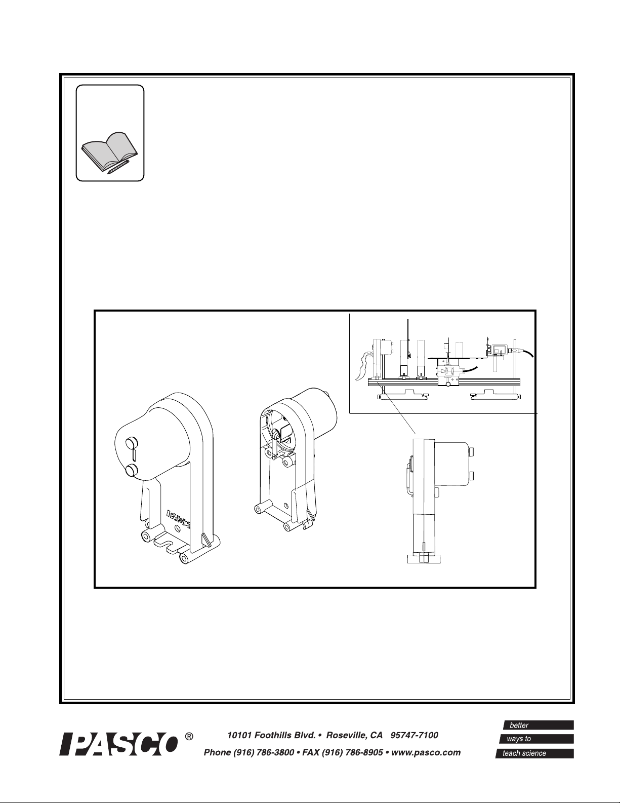
This manual describes setup, operational, and procedure guidelines for conducting a black body experiment
using the OS-8537 Educational Spectrophotometer, OS-8542 Black Body Light Source and the OS-8543 Black
Body Prism with Infrared Filter.
The Black Body Prism comes with the necessary accessories for mounting the prism onto the
spectrophotometer table of the PASCO OS-8537 Educational Spectrophotometer. The Black Body Prism is
designed to convert the PASCO Model OS-8539 Educational Spectrophotometer from a grating to a prism
spectrophotometer. A prism spectrophotometer has two advantages over a grating spectrophotometer: a) it
eliminates overlap of orders observed with a grating (When a grating is used, second order visible
wavelengths overlap first order infrared wavelengths.), and b) the spectrum is brighter because it does not
spread over several orders or in both directions.
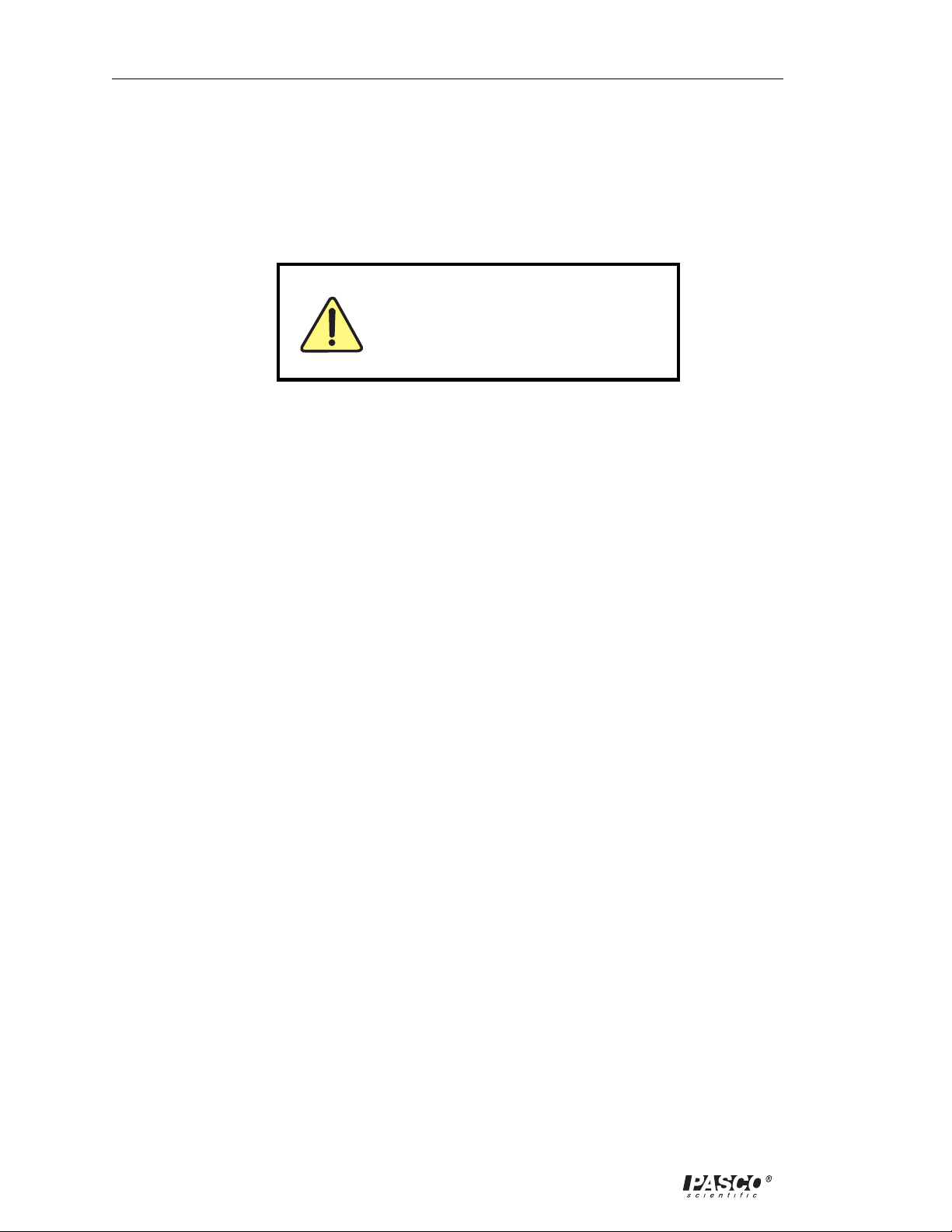
Equipment Required:
• OS-8542 Black Body Light Source
• OS-8543 Black Body Prism with infrared filter, filter bracket and beveled stop piece
PASCO
BLACK BODY PRISM
OS-8543
Black body light source Prism mount with prism
Also Required:
• Educational Spectrophotometer System (OS-8539)
Filter bracket (with filter) for
the infrared light sensor
infrared
filter
• 0-10 VDC Power Supply (1 A) (SE-9720) Or Power Amplifier (CI-6552)
• Science Workshop Interface (Model 750 or 700)
Stop piece for the
light sensor arm
• PASCO Infrared Sensor (CI-6628)* Or High Sensitivity Light Sensor (CI-604)**
• DataStudio™ software
• Setup CD for the Black Body experiment
• 1 package containing 10 tungsten light bulbs (9 for replacement in the black body light source)
*Use the infrared sensor for black body experiments or when you want to measure infrared wavelengths.
**Use the high sensitivity light sensor for experiments in which only visible wavelengths are desired and a linear response is not needed.
1
Page 6
Black Body Instruction Manual 012-07105B
Theory
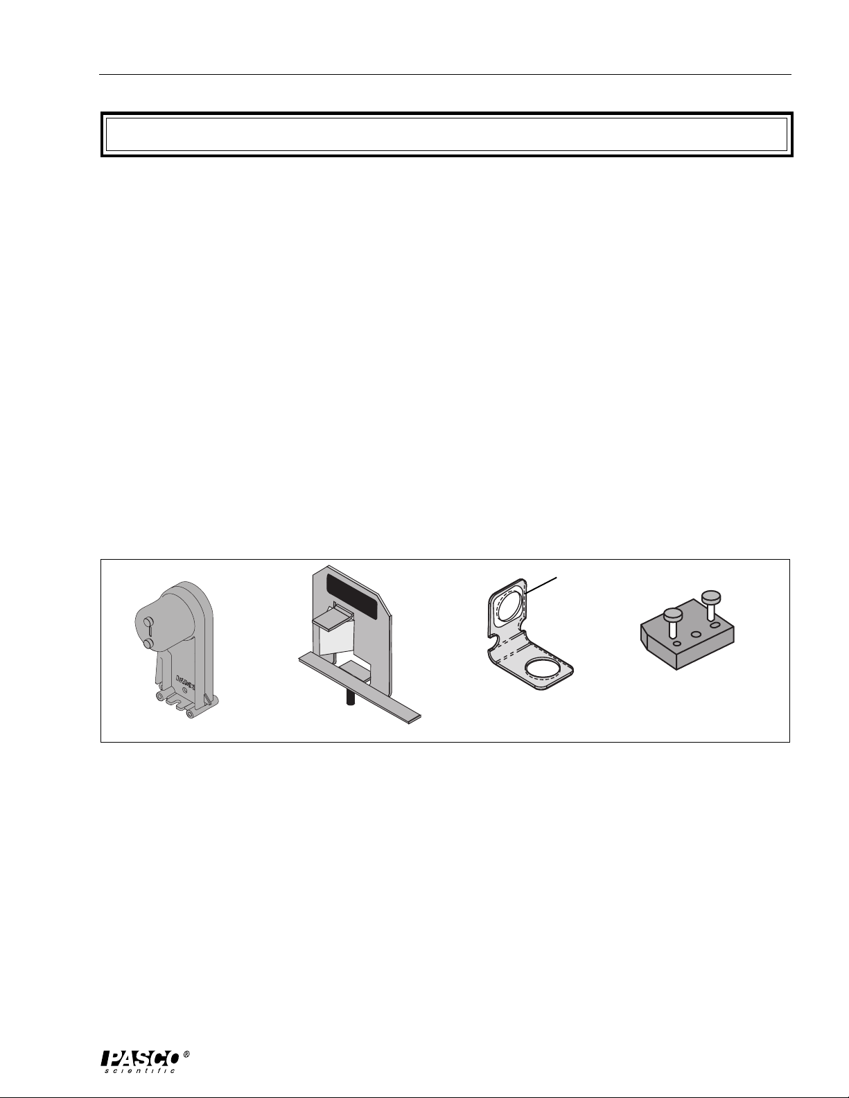
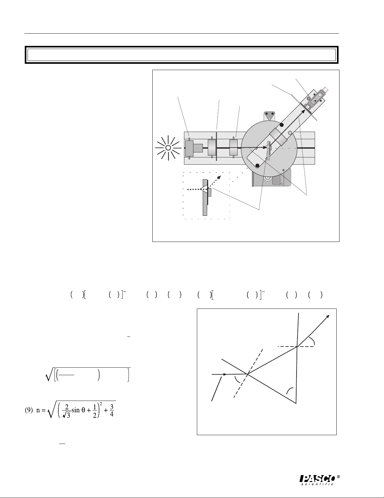
The 60-degree prism is mounted so that the
back face is perpendicular to the incoming
light, as shown in Figure 1. A schematic of
the prism and the path of light is shown in
Figure 2 below. Since the prism angle is 60
degrees, it can be shown that
(1) θ2+ θ3=60°
And using Snell’s law at each interface,
(2) sin (60°) = n sin (θ2) and
(3) sin (θ) = n sin(θ3)
Combining equations (3) and (1) yields
(4) sin (θ) = n sin (60° – θ2)
which, using the double angle formula
becomes
black body light
light sensor
aperture slits
collimating slits
collimating lens
prism mount
with prism
GAIN
1
10
100
direction of light
Figure 1: Path of Light Through the Prism
Spectrophotometer
(5) sin (θ) = n{ sin (60°) cos (θ2) – sin (θ2) cos (60°)}
Now use a trig identity to change from cos to sin, and (5) becomes
1
(6) sin θ = n sin 60° 1 – sin2θ
2
– n sin θ2cos 60°
2
= sin 60° n2–n2sin2θ
If we now use (2), equation 6 becomes
1
(7) sin(θ) = sin(60°)[n2– sin2(60°)]
2
– sin(60°)cos(60°)
Solving (7) for n gives
(8) n =
sinθ
+ cos602+ sin260
sin60
And finally, if we simplify,
path of light
The Cauchy equation gives the relationship between the
wavelength and the index of refraction.
(10) n(λ)=
A
+ B
2
λ
where A and B depend on the type of glass.
1
2
– n sin θ2cos 60°
2
θ
3
θ
2
60°
n
60°
Figure 2: Schematic of a Prism
θ
2
Page 7
012–07105B Black Body Instruction Manual
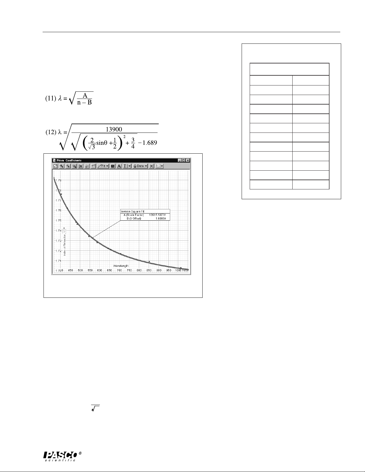
Table 1 shows the values for the prism used. The graph in Figure 3
shows an inverse square fit of the data.
Thus, we get the values of A=13,900 and B=1.689
with the wavelength given by
Thus, the final equation for the wavelength (in nanometers) is
Table 1: Prism Coefficients
ataD,stneiciffeoCmsirP
)mn(htgnelevaWxednInoitcarfeR
007.404677.1
008.534267.1
000.084847.1
001.684647.1
001.6454
006.785827.1
008.346227.1
003.656127.1
005.607717.1
001.258907.1
000.4101307.1
37.1
Figure 3: Relationship between refraction index
and wavelength for light passing through a prism
Determination of the Wavelength from the Angle (using DataStudio)
In DataStudio, the equation for determining the wavelength is listed in the Definition box in the Calculator
window, as follows:
Wavelength = filter (0,8000, (13900/(((1.1547*sin ((Init - Angle)/Ratio))^2 + 0.75)^0.5 - 1.689))^0.5)
where 0,8000 is the filtering range for the infrared light (0-8000 nm)
13,900 is constant A, as described above.
1.689 is constant B, as described above.
1.1547 is
2
3
Init - is the initial angle reading measured during data collection
Angle - is the angle measured by the rotary motion sensor
Ratio - is the ratio of the disk radius to the pin radius
3
Page 8

Black Body Instruction Manual 012-07105B
0
K
K
B. Determining the Temperature of the Black Body Light Source
The temperature of a hot bulb can be calculated from a known resistance at room temperature. The
resistance of the bulb is given by
(13) R = R0[1 – α0(T – T0)]
where α0 is the thermal coefficient at room temperature. The bulb filament is made of tungsten,
which has a coefficient of α0 = 4.5 x 10⁻³/0K at room temperature. Solving equation (13) for the hot
temperature gives
R
–1
R
(14) T = T0+
0
α
The bulb has an approximate resistance of 0.84Ω at room temperature. For a more exact value,
measure it yourself. You cannot measure the resistance of the bulb while it is still in the holder.
Solder wire leads to one bulb to ensure a good contact, and use this bulb to determine the resistance.
To determine the resistance of the hot bulb, measure the voltage drop across the bulb and the current
passing through it; use Ohm’s law, where V=IR.
The current is determined from the power amplifier output from Channel C. Connect a voltage
sensor to channel B, and place it directly across from the light source. The final equation for the
temperature (in Kelvin) of the bulb becomes
VIV
I
–1
(15) T=300K +
0.84
4.5 x 10
4.5 x 10
–3
–3
Determining the Temperature of the Bulb Using DataStudio
In DataStudio, the temperature for the bulb in the black body light source can be viewed
from the definition box in the Calculator. To view the equation for temperature, click on
the calculator icon next to temperature (under the “Data” window). The equation is as
follows:
Temp (K) = 300 + ((voltage/current)/0.84 - 1)/.0045
where voltage is the voltage across the bulb
current is the current passing through the bulb
0.84 is the resistance of the bulb at room temperature
.0045 is 4.5 x 10
-3
4
Page 9

012–07105B Black Body Instruction Manual
Setup
This section describes the procedure for mounting the light sensor arm, prism mount and black body light
source. For more detailed instructions about setting up the spectrophotometer table and rotary motion sensor,
see the PASCO OS-9539 Educational Spectrophotometer System Instruction Manual. Before proceeding,
calibrate the rotary motion sensor, as described in the “Calibration” section on page 9 of this manual.
1. Attach the Stop to the Light Sensor Arm
Attach the stop to the light sensor arm using the two screws
provided (Figure 4). Note the orientation of the stop.
Position the beveled corner of the stop so that it will hit
against the angle indicator on the spectrophotometer table.
beveled corner
stop piece
2. Mount the Light Sensor arm to the Degree Plate
Align the Light Sensor arm over the bracketed markers and
the edge holes displayed on the top surface of the degree
plate. Use the thumb screws to secure the arm to the plate.
After securing the arm, check to ensure that the arm rotates
throughout the full range between the zero mark and the
stop.
3. Attach the Prism Mount to the Degree Plate and
Spectrophotometer Table
Remove the wing nut and lock washer from the prism
mount. Set the angle indicator on the spectrophotometer
table to zero. Locate the hole in the center of the circular
table on the spectrophotometer. Screw the prism mount
into this center hole (Figure 6).
Note: Do not screw it down tight. The light sensor
arm must be free to rotate under the prism without
touching the prism mount.
Rotate the prism mount until it clears the light sensor arm
and the prism is oriented with its apex pointed in the
direction of the light source, and the prism mount bracket is
aligned with the 0 and 180 degree lines on the plate.
Check to see that the angle indicator on the degree plate is
set to zero and the tab indicator on the prism mount is
aligned parallel to the 180-degree line on the plate. From
the bottom side of the degree plate, place a lock washer
and wingnut on the threaded post to help secure the prism
mount onto the table.
light sensor arm
Figure 4: Attach the stop piece to the
light sensor arm
angle
0
light sensor arm
pinion
indicator
zero-degree
mark
degree
plate
Figure 5: Mount the Light Sensor Arm to the
Degree Plate
prism mount
G
AIN
1
10
angle
indicator
PASCO
BLACK BODY PRISM
OS-8543
100
HIGH SENSITIVITY
604
I-6
LIGHT SENSOR
C
tab indicator
180-degree mark
Figure 6: Attach the Prism Mount to the
Spectrophotometer Table
5
Page 10

Black Body Instruction Manual 012-07105B
INFRARED SENSOR
CI-6628
4. Replace the Light Sensor with the Infrared Sensor and
Infrared Filter
To observe infrared wavelengths, use the Infrared Sensor
instead of the High Sensitivity Light Sensor. The filter prevents
the infrared sensor from detecting objects in the room (such as
people’s hands), but still allows the sensor to detect hotter
objects (such as a light source).
a) To replace the High Sensitivity Light Sensor, rotate the
threaded post clockwise to loosen the attachment and
remove the light sensor.
b) Place the base of the filter bracket over the front hole of the
light sensor mount, such that the hole in the bracket base
aligns over the front hole on the mount and the front
hole of the light sensor arm.
c) Place the Infrared Light Sensor over the base of the
bracket. While holding the sensor in place with one
hand, use your other hand to insert the threaded
post from beneath the sensor. Rotate the post
until the sensor holds firmly in place against the
bracket and mount. The glass filter should fit snugly
against the sensor, with the bracket under the case
(Figure 8).
collimating slits
black body
filter bracket
light sensor arm
threaded post
Figure 7: Replacing the light sensor
collimating lens
prism mount
infrared filter
light sensor
mount
focusing lens
aperture disk
light sensor
HIGH SENSITIVITY
LIGHT SENSOR
PASCO
scientific
CI-6604A
5. Position the Collimating Slits and Lenses on the
Figure 8: Equipment Setup
Optics Track.
a) Place the collimating lens close to but not touching the degree plate.
b) Place the collimating slits exactly 10 cm from the collimating lens.
6. Mount the Black Body Light Source onto the Optics Track
Slide the black body light source onto the light end of the optics track. Place the light source as close as
possible to the collimating slits. For added stability, use the screw and nut to secure the black body light
source to the track (see Figure 8).
7. Connect the Power Supply to the Black Body Light Source
Use banana plugs to attach a power amplifier (used with a ScienceWorkshop interface) with signal
generator capacity.
Note: A D.C. power supply can be used if a power amplifier is not available. However, the power
amplifier is needed for displaying temperature and wavelength in DataStudio.
a) With the amplifier turned off, attach the banana plugs on the black and red cables from the CI-6502
Power Amplifier to the connectors on the back side of the black body light source.
b) Plug the DIN connector from the amplifier into analog channel C.
6
Page 11
012–07105B Black Body Instruction Manual
8. Science Workshop Interface Setup (for use with DataStudio™ software)
With the power on the interface turned off, connect the following:
a) Rotary Motion Sensor - plug the yellow cable into digital channel 1 on the interface. Plug the black
cable into digital channel 2.
b) Light Sensor - plug the DIN connector into analog channel A
c) Voltage Sensor - plug the DIN connector (extending from the black and red cables) into analog
channel B and to the banana plug jacks in the back side of the Black Body light source.
9. Setup the Experiment in the DataStudio™ software
1) Insert the DataStudio Setup CD into the CD drive of your computer.
Note: You must have PASCO’s DataStudio™ software loaded on your system to run the experi-
ment with the DataStudio setup CD. The setup CD is not designed to be run with
ScienceWorkshop® or other software. The following instructions apply to DataStudio and
are subject to change with future updated releases of DataStudio software and/or
DataStudio experiment setup CDs.
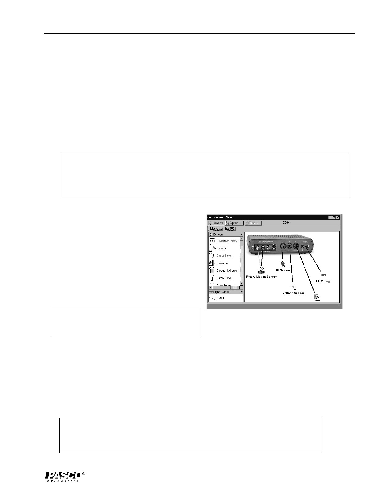
2) Click on the Experiment Setup window.
Select from the list of sensors displayed
in the sensors list. Drag each sensor icon
to the corresponding channels on the
ScienceWorkshop interface box display.
3) Verify or change (if desired) the voltage and current
settings in the Signal Generator Box:
recommended voltage setting = 7 volts
recommended sampling rate = 50 Hz
Note: To view the Signal Generator dialog box,
doubleclick on the Output icon located under the Signal
Figure 9: Experiment Setup Window
Output drop down menu.
4) Prepare the graph displays in DataStudio.
Using DataStudio, you can view the following graphs when you create the appropriate
horizontal (x) and vertical (y) axes:
a) Light Intensity vs. Wavelength
b) Light Intensity vs. Angular Position
c) Voltage vs. Time
d) Temperature vs. Time
Note: Prepare a graph display by dragging and dropping the appropriate run icons
over the x and y axes in an open graph. You can also change a graph display by
clicking on the Graph Settings button (the right most button on the top horizontal bar
in the graph window.)
7
Page 12

Black Body Instruction Manual 012-07105B
Example: Generate a graph display of light intensity vs. angular position.
From the “Displays” list, doubleclick on a graph icon. Drag and drop a voltage icon over the y-axis
label on the graph. Drag and drop a angular position icon over the x-axis label on the graph. (For
more detailed information about DataStudio, refer to the DataStudio online help guide listed under
the HELP menu in the software.)
Note: If your graph displays negative angles, try reversing the position of the black and yellow
cables you have inserted into channels 1 and 2.
**IMPORTANT OPERATIONAL NOTES**
The following notes are critical to maintaining the accuracy of the calibrations and experiment:
Setting the Collimating Slits - For best results, match the slit width size on the collimating lens to the
same slit width size on the aperture. For example, if you select the number 4 width from the collimating slits, select the number 4 width on the aperture. (For more information about adjusting the
collimating slits, see the Instructional Manual for the Model OS-8539 Educational Spectrophotometer.)
Ensure the slit opening on the aperture slides directly over the hole on the back of the aperture
bracket; otherwise light will not reach the light sensor.
Adjusting the Voltage in the Black Body Light Source - In DataStudio, set the voltage in the Signal
Generator box. The recommended voltage setting is 7 volts. The voltage can be varied from zero to
10V, but continuous operation of the bulb at 10V will result in a shorter bulb life.
In DataStudio, display the temperature graph and ensure the voltage increase corresponds to a temperature increase. The sampling rate is set to 50 Hz. Also, in DataStudio, ensure that you have
selected DC voltage in the Signal Generator box; do not select sine wave or another function. The
black body experiment requires direct and continuous current, not alternating or pulsating current.
To improve the voltage signal display on the graphs, increase the gain on the light sensor to 10 or
100. In the Signal Generator window, use the arrow keys to adjust the gain.
Checking the position of the prism - The prism mount and prism must remain fixed at all times. If
not, your data will be in error. If the prism mount rotates at any time during the scanning, discard the
data, recalibrate, and take another reading.
Checking the angular display against the reading on the degree plate - DataStudio allows you to
adjust the angle units to either degree or radians. If you set the units to rads in DataStudio, remember
that the number on the degree plate will not correspond to the number on the display. You will need
to mathematically convert degrees to radians.
If you have negative angle readings, you may have reversed the colored cables for the rotary motion
sensor, rotated the degree plate in the wrong direction, or improperly mounted the light sensor arm
and lenses. While taking a reading, the degree plate must rotate clockwise. For more information
about the rotary motion sensor or the light sensor arm, see the instruction manual for the Educational
Spectrophotometer.
8
Page 13

012–07105B Black Body Instruction Manual
Calibration
1. Calibrate the Rotary Motion Sensor
Determining the wavelength from the prism spectrophotometer requires and exact measurement of the
angle. To calibrate the rotary motion sensor, determine the ratio of the disk radius to the pin radius
(approximately 60:1) as follows:
a) Remove the prism mount and the light sensor bracket from the degree plate by unscrewing the two
small thumbscrews. Start the DataStudio program and select a rotary motion sensor. Make a
digits display of the angular position, and turn the degree plate so that the zero degree mark is
exactly aligned with the index mark.
b) Start recording data. Slowly and continuously turn the degree plate clockwise for exactly one
complete rotation.
c) Stop recording data. Record the maximum value of the angle. Divide this number by 360 (or 2π if
it is in radians mode). This is the ratio of the radii. Record this number in the calculator in
DataStudio.
2. Tare the Light Sensor
Note: For best results and to avoid measurement drift, tare the light sensor before scanning
the spectrum and/or before each experiment run. To turn the light source on, click the On
button in DataStudio’s Signal Generator box.
a) Rotate the light sensor arm until it hits the stop against the angle indicator on the spectrophotometer
table.
b) Block the light source by placing your hands between the collimating slits and the collimating lens.
c) While the light is blocked, press the tare button on the light sensor to zero the sensor.
Procedures
A. Scanning a Spectrum
1. Tare the light sensor (as described in the section above).
2. Remove your hand to unblock the light and start recording data (Click the Start button in the
DataStudio setup window) on the computer. Slowly rotate the light sensor arm through the spectrum.
3. To determine the initial angle from the light source, continue to rotate the arm until the light sensor
has passed through the white light that passes under the prism (i.e the degree plate has rotated
pass the zero degree mark).
9
Page 14

Black Body Instruction Manual 012-07105B
4. Stop recording data. The initial angle (when the
stop is against the angle indicator) is required to
calculate the wavelength.
Angle to white light
Initial angle
5. In DataStudio, make a graph of intensity vs. angular
position. Measure the angle to the white light that
passes directly through the spectrophotometer and
under the prism. This angle is subtracted from all
angles, so that all angles are referenced from the
reference line (the parallel beams that travel in a
straight line through the spectrophotometer).
Figure 10: Measuring the Angle of the
Refracted Light (Using DataStudio)
6. Enter the intial angle as “Init” into the wavelength
calculation in the DataStudio calculator.
Experiment
A. Black Body Spectrum: Scanning Nested Curves from Black Bodies of Different Temperatures
Note: Before running the experiment, perform the rotary motion sensor calibration, as described in
the “Calibration” section on page 9. Enter this calibration as “Ratio” into the DataStudio calculator,
and click the Accept button.
1. Rotate the light sensor arm until it hits the stop against the angle indicator on the circular table.
Note: Before proceeding, the black body light source must be turned on and emitting light.
If not, click the On button in DataStudio’s Signal Generator dialog box.
2. Block the light source by placing your hand between the collimating slits and the collimating
lens. While the light is blocked, press the tare button on the light sensor to zero the sensor.
3. Remove your hand to unblock the light and start recording data on the computer. Click the Start
button in the DataStudio setup window, and slowly rotate the light sensor arm through the spectrum.
4. After you have scanned through the spectrum, stop rotating the arm, continue recording and
push the tare button again. Place your hand between the collimating slits and the collimating lens
to block the light and return the light sensor arm to its original position against the stop. Block
ing the light during this time causes the return scan to be below the axis of the graph, so it does
not trace back over the black body data.
5. a) Change the temperature of the bulb by changing the voltage applied to the bulb. You get tem-
perature from current and voltage, as shown by
Temp.(K) = 300 + ((voltage/current)/0.84 - 1/.0045).
b) For each temperature, determine the maximum peak (λ
displacement law, where λ
T =2898 μm ⋅ K, to calculate the λ
max
) of the wavelength. Use the Wien
max
max
.
10
Page 15

012–07105B Black Body Instruction Manual
Experiment (Continued)
6. Repeat steps 1 through 5 to get nested curves. On the last scan, continue the scan to the zerodegree mark so that you can obtain an exact determination of the initial angle. When you have
finished all 5 runs, click the Stop button in Data Studio.
Note: To avoid measurement drift, you must tare the light sensor (steps 1 and 2) before each
subsequent scan through the spectrum.
EXPERIMENT NOTES AND OBSERVATIONS:
(Use the following space to perform calculations and make note of your observations during the experiment.)
11
Page 16

Black Body Instruction Manual 012-07105B
Data Collection and Analysis
When you are ready to scan the spectrum, click the Start button in the DataStudio setup window. Data
Studio records the results and automatically performs the calculations for you. When you have finished
collecting your data, click the Stop button and view your results in either a graph or a table. If
necessary, you can view voltage, wavelength, angle and temperature data points all in the same run.
To view individual data points in a table, doubleclick to open a table icon, click on a colored data run
icon, and drag and drop the colored data run into the table. (For more information about data analysis
using DataStudio, refer to the DataStudio online help guide.)
Sample Data
12
Page 17

012–07105B Black Body Instruction Manual
Teacher’s Guide
Theory of the Black Body Experiment
An incandescent light source that emits light through a small cavity is a “perfect emitter.” By definition, a perfect
light emittter is one that emits light rays throughout an infinite number of frequencies in the visible and invisible
electromagnetic spectrum. When light from the black body is cast through a prism, the observed spectrum is
continuous, and no overlapping of the spectral lines occurs.
In this experiment, parallel light rays travel through the collimating lens, which allows the light rays to remain
parallel. Passing through the prism, the light rays refract and project in front of the aperture slit over the light
sensor. The light sensor detects and records the light intensity as voltage.
Unlike other light sources, changes in light intensity from an incandescent black body is solely dependent on
temperature. Increasing the temperature of the black body light source increases the light intensity. For any given
temperature, there appears to be an optimal wavelength for reaching a maximum light intensity.
The angle of the emitted light depends upon the refraction index of the prism and the wavelength of the rays.
Shorter wavelengths show more “bend” than longer wavelengths and therefore exihibit higher indices of refraction.
Notes:
1. See the Operational Notes section of this manual for important setup reminders.
2. Before beginning the experiment, have students do the following:
a) Set the collimating and aperture slits.
b) Check the position of the prism.
c) Ensure the cables from the rotary motion sensor are properly inserted into ScienceWorkshop.
d) Check to see that the black body light is turned on and is emitting steady light.
Students can turn the bulb on from the Signal Generator box in DataStudio. If the bulb does not turn on or
emits intermittent bursts of light, see the Troubleshooting section of this manual.
Sample Data
Calibration:
Init Angle: 76.8 degrees (1.33 rads)
Ratio of plate to pin radius: 59.740
Procedure: Scanning a Spectrum
Spectrum Color (deg) θ(rads) n
λ
Red 58 1.01 1.714 746
Yellow 59 1.03 1.717 705
Green 60 1.05 1.732 569
Blue 61 1.06 1.741 517
Violet 62 1.08 1.749 481
13
Page 18

Black Body Instruction Manual 012-07105B
Teacher’s Guide (Continued)
Activity 1: Black Body Temperatures
Data Run Time (s) Volts ΔV Temp. (K) ΔT (rads)
λ
1 12.06 1 1 2762.983 ----- 661 12.9
13.40 2 1 2764.252 2.269 741 13.6
14.56 3 1 2764.464 0.212 803 14.0
14.56 4 1 2766.554 2.090 862 14.3
17.14 5 1 2767.513 0.959 933 14.7
19.90 6 1 2771.716 4.203 1046 15.0
Black Body Experiment - Sample Graphs (Data Studio)
Note: The window appearances in the following graphs are subject to change
with updated versions of the DataStudio software.
Light Intensity vs. Wavelength
Light Intensity vs. Angular Position
Questions/Exercise for Students:
1) How does changing the temperature of the bulb affect the wavelength or light intensity? Do you notice a
pattern with increasing temperature?
2) From what you remember from the lesson on the grating spectrophotometer, what differences have you
observed between using a prism and a grating?
3) On a piece of paper, draw a diagram showing the position of the reference angle, measured angle and
spectral lines. Do the spectral lines converge or diverge? Do the light rays overlap?
4) What would happen if you removed the collimating lens?
5) What is the relationship between the light’s angle, wavelength and intensity?
6) What differences do you notice between the black body and other types of light sources you have used?
7) Replace the infrared light sensor with the high sensitivity light sensor. What differences do you notice
in the graph displays?
14
Page 19

012–07105B Black Body Instruction Manual
Teacher’s Guide (Continued)
Answers to Questions from Page 14
1) The intensity of the light is related to the temperature of the bulb by IαT4. The higher the bulb temperature, the
higher the intensity that the light ray becomes. The peak wavelength is shifted to higher frequencies (and
shorter wavelengths) at higher temperatures.
2) A prism spectrophotometer has two advantages over a grating spectrophotometer: a) it eliminates overlap of
orders observed with a grating. (When a grating is used, second order visible wavelengths orverlap first order
infrared wavelengths.), and b) the spectrum is brighter because it does not spread over several orders or in
both directions.
3) The spectral lines converge at a point in front of the light sensor. However, beyond the light sensor, light rays
diverge. The light rays do not overlap.
4) The collimating lens allows the light rays to travel parallel to one another before passing through the prism.
The parallel lines serve as a reference to compare to when measuring the angle of refraction.
If you remove the collimating lens, the waves will refract and reflect off of the various objects in the room
before reaching the prism. These waves would bend at various angles, and would make it difficult to
determine a reference line for the path of light travel through the prism. You would not be able to obtain an
accurate measurement of the refracted angle.
5) The angle of a wave is directly related to its ability to refract. The larger the angle, the greater the “bend” or
refraction, and the shorter the resulting wavelength. For any given temperature, there appears to be an
optimal wavelength for reaching a maximum light intensity.
6) Unlike other light sources, changes in light intensity from an incandescent black body is solely dependent on
temperature. The spectra of an incandescent light source are continuous and rainbow colored. Gas light
sources display discrete spectra.
7) The graphs display waves between 400-700 nm because the high sensitivity light sensor detects light in the
visible region of the electromagnetic spectrum. With the high sensitivity light sensor, you will not be able to
observe waves of infrared light, which are typically greater than 750 nm and lie in the invisible region of
the electromagnetic spectrum.
15
Page 20

Black Body Instruction Manual 012-07105B
Troubleshooting
Problem: The light sensor arm does not rotate throughout the full range of motion.
Solution: Loosen the screw underneath the prism mount and/or the screws on the top of the degree
plate. Check that the diameter of the screw is the proper fit. If not, use a different size
screw.
Problem: The angle readings on the graph display are negative.
Solution: Check to ensure that you have properly inserted the colored cables into digital channels on the
ScienceWorkshop interface box. (For instructions, see “Setup” in this manual).
Problem: The stop on the light sensor arm does not touch the angle indicator.
Solution: Loosen the wing nut from below the spectrophotometer table. If necessary, also loosen the
thumb screws on the top of the degree plate.
Problem: The graph does not display a voltage reading or voltage readings are negative.
Solution: Check to ensure the following: a) The power amplifier is connected to the ScienceWorkshop
interface. b) The banana plugs are properly inserted into the back side of the black body light
source. c) The DIN connector extending from the black and red cables is properly inserted
into channel B of the ScienceWorkshop interface. d) In DataStudio, the “on” button in the
Signal Generator Box is depressed. (For more instructions, see “Setup” in this manual.)
e) Ensure you have the signal set to DC voltage in the Signal Generator box in DataStudio.
f) If steps a-e fail to correct the problem, you may have a faulty light sensor. To order a
new light sensor, see the “Parts and Replacements” section of this manual.
Problem: The black body light does not turn on.
Solution: Check to ensure the following: a) The connections of the banana plugs tightly fit into the
female connector holes on the back side of the black body b) The DIN connector extending
from the red and black cables is properly inserted into the ScienceWorkshop interface c) In
DataStudio, the “on” button in the Signal Generator box is depressed. If your connections are
set properly and the bulb still does not turn on, replace the bulb.
To avoid the risk of burns or shock, do not try to replace the bulb
while the light source is turned on. Before replacing the bulb, turn the
power supply off, and click the Off button in DataStudio’s Signal
Generator box.
Problem: The black body emits pulsating, rather than steady light.
Solution: In DataStudio, open the Signal Generator box window and change the setting to DC voltage. If
the you already have the signal set to DC voltage, you may need to replace the bulb.
Problem: The graph does not show a wavelength reading.
Solution: Check to ensure that the aperture slit opening on the aperture slides directly over the hole on
the back of the aperture bracket; otherwise light will not reach the sensor to record a reading.
If necessary, you can adjust the gain of the signal using the gain switch on top of the infrared
sensor.
16
Page 21

012–07105B Black Body Instruction Manual
Parts and Replacements
To order replacements, call 1-800-772-8700 (inside the U.S.A.) or (916) 786-3800 (outside the U.S.A.)
1. Black Body Light Source - A package of 10 replacement bulbs (526-040) comes included in the Prism
Spectrophotometer Kit. To replace the bulb, loosen the two screws from the front face of the light source
and remove the slotted over. To order more bulbs, use part no. 012-07105.
To avoid the risk of burns or shock, do not try to replace the bulb while
the light source is turned on. Before replacing the bulb, turn the power
supply off, and click the Off button in DataStudio’s Signal Generator
box.
2. Infrared Filters - To order a replacement glass filter, use part no. 636-06912.
3. Infrared Light Sensor - In the event you have received a malfunctioning sensor, see the Warranty and Equipment
Return section described in the front of this manual.
17
Page 22

Black Body Instruction Manual 012-07105B
Notes
18
Page 23

012–07105B Black Body Instruction Manual
Technical Support
Feedback
If you have any comments about the product or
manual, please let us know. If you have any
suggestions on alternate experiments or find a
problem in the manual, please tell us. PASCO
appreciates any customer feedback. Your input helps
us evaluate and improve our product.
To Reach PASCO
For technical support, call us at 1-800-772-8700
(toll-free within the U.S.) or (916) 786-3800.
fax: (916) 786-3292
e-mail: techsupp@pasco.com
web: www.pasco.com
Contacting Technical Support
Before you call the PASCO Technical Support staff, it
would be helpful to prepare the following
information:
➤ If your problem is with the PASCO apparatus,
note:
- Title and model number (usually listed on the
label);
- Approximate age of apparatus;
- A detailed description of the problem/sequence
of events (in case you can’t call PASCO right
away, you won’t lose valuable data);
- If possible, have the apparatus within reach
when calling to facilitate description of
individual parts.
➤ If your problem relates to the instruction manual,
note:
- Part number and revision (listed by month and
year on the front cover);
- Have the manual at hand to discuss your
questions.
The exclamation point within an equilateral
triangle is intended to alert the user of important
operating and safety instructions that will help
prevent damage to the equipment or injury to
the user.
19
 Loading...