

Page 1
Includes
Teacher's Notes
and
Typical
Experiment Results
Instruction Manual and
Experiment Guide for
the PASCO scientific
Model OS-8536
OPTICS TABLE
012-06557A
1/98
R
O
L
S
O
C
O
U
L
R
I
G
C
H
E
B
O
T
A
S
S
-8
IC
Y
5
A
1
O
R
7
S
T
BEFORE CHANGING BULB.
I
P
L
DISCONNECT POWER
T
S
IC
WITH FINGERS.
DO NOT TOUCH BULB
S
1
3
BULB: 12V 10W G-4
5
PASC O
s
c
i
e
POWER SUPPLY JACK
12V @ 800mA
INSTRUCTION MANUAL.
TO REPLACE BULB SEE
GENTLY SPREAD BRACKET.
TO REMOVE LIGHT SOURCE
n
t
i
f
i
c
© 1998 PASCO scientific $10.00
Page 2

Page 3

012-06557A Optics Table
T able of Contents
Section Page
Copyright, Warranty, and Equipment Return .....................................................ii
Introduction ......................................................................................................1
About the Experiments......................................................................................2
Basic Experiments
Experiment 1: Reversibiltiy ...............................................................3
Experiment 2: Dispersion ..................................................................5
Other Experiments Using the Basic Optics System
Experiment 3: Prisms ........................................................................7
Experiment 4: Reflection – Plane and Curved Mirrors .......................8
Experiment 5: Snell’s Law ................................................................9
Experiment 6: Total Internal Reflection ............................................10
Experiment 7: Refraction – Convex and Concave Lenses.................. 11
Experiment 8: Lensmaker’s Equation ...............................................12
Experiment 9: Apparent Depth .........................................................13
Teachers Guide ..................................................................................15
Technical Support ......................................................................... Inside Back Cover
i
Page 4
Optics Table 012-06557A
Copyright, Warranty and Equipment Return
Please—Feel free to duplicate this manual
subject to the copyright restrictions below.
Copyright Notice
The PASCO scientific Model OS-8536 Optics Table
manual is copyrighted and all rights reserved. However,
permission is granted to non-profit educational institutions for reproduction of any part of this manual providing the reproductions are used only for their laboratories
and are not sold for profit. Reproduction under any other
circumstances, without the written consent of PASCO
scientific, is prohibited.
Limited Warranty
PASCO scientific warrants this product to be free from
defects in materials and workmanship for a period of one
year from the date of shipment to the customer. PASCO
will repair or replace, at its option, any part of the product
which is deemed to be defective in material or workmanship. This warranty does not cover damage to the product
caused by abuse or improper use. Determination of
whether a product failure is the result of a manufacturing
defect or improper use by the customer shall be made
solely by PASCO scientific. Responsibility for the return
of equipment for warranty repair belongs to the customer.
Equipment must be properly packed to prevent damage
and shipped postage or freight prepaid. (Damage caused
by improper packing of the equipment for return shipment will not be covered by the warranty.) Shipping
costs for returning the equipment, after repair, will be
paid by PASCO scientific.
Equipment Return
Should this product have to be returned to PASCO
scientific, for whatever reason, notify PASCO scientific
by letter or phone BEFORE returning the product. Upon
notification, the return authorization and shipping instructions will be promptly issued.
➤ NOTE:
NO EQUIPMENT WILL BE ACCEPTED FOR
RETURN WITHOUT AN AUTHORIZATION.
When returning equipment for repair, the units must be
packed properly. Carriers will not accept responsibility
for damage caused by improper packing. To be certain
the unit will not be damaged in shipment, observe the
following rules:
➀ The carton must be strong enough for the item
shipped.
➁ Make certain there is at least two inches of packing
material between any point on the apparatus and the
inside walls of the carton.
➂ Make certain that the packing material can not shift in
the box, or become compressed, thus letting the instrument come in contact with the edge of the box.
Address: PASCO scientific
10101 Foothills Blvd.
Credits
This manual authored by: Dave Griffith
P.O. Box 619011
Roseville, CA 95678-9011
Phone: (916) 786-3800
FAX: (916) 786-8905
ii
Page 5
012-06557A Optics Table
Introduction
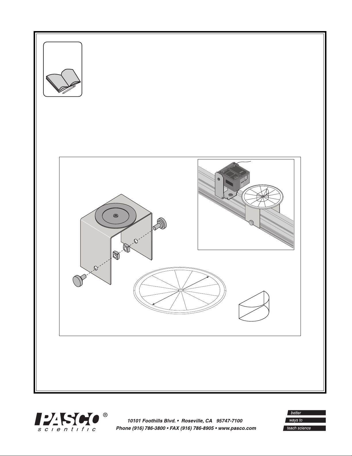
The PASCO OS-8536 Optics Table includes:
– cylindrical lens
– ray table
– ray table base and mounting hardware
The lens, ray table, and ray table base are designed to be
used with the Optics Bench, Ray Optics Kit, and Light
Source which are included in the OS-8515 Basic Optics
System.
Cylindrical Lens
The Cylindrical Lens is a “D”-shaped piece of clear
acrylic plastic. The lens is one inch (2.54 cm) thick, and
the radius of curvature is one inch (2.54 cm).
Ray Table
The Ray Table is a metal disk six inches (15.24 cm) in
diameter with a degree scale printed on both sides. In addition, the center of one side has a Cartesian grid marked
in millimeters (mm). The Ray Table has a hole in its center which fits over the post on the top of the Ray Table
Base.
Ray Table Base
The top side of the Ray Table Base has a ring of magnetic
material that holds the Ray Table in position when the
Ray Table is placed on the post on the top of the table.
The mounting hardware on each leg of the Ray Table
Base consists of a square nut and a thumbscrew. The
square nuts fit into the T-slot on each side of the Optics
Bench that is a part of the OS-8515 Basic Optics System.
Tightening the thumbscrews holds the Ray Table Base in
position when it is mounted on the Optics Bench.
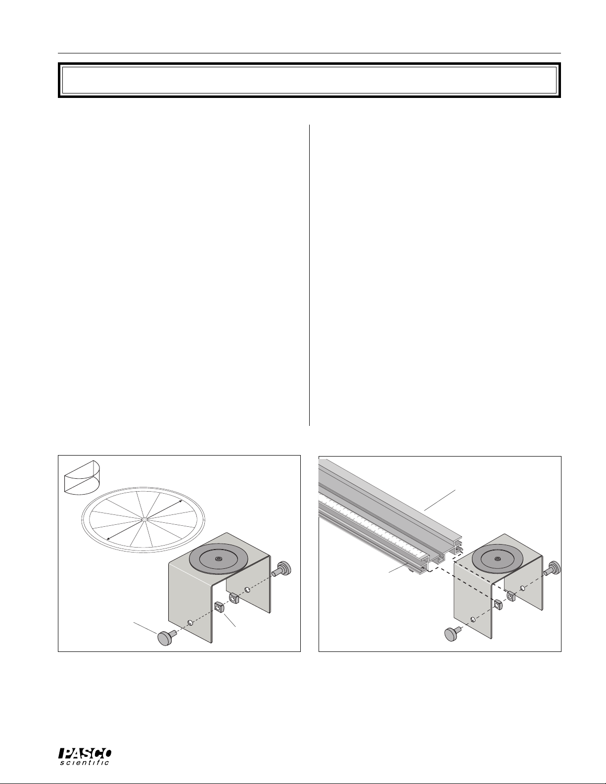
Mounting the Ray Table Base t o the Optics
Bench
Loosen each thumbscrew by turning counter-clockwise.
Leave the square nut on the end of each thumbscrew. Attach the Ray Table Base to the Optics Bench by inserting
the square nuts into the T-slots on each side of the track.
The base can be moved to any position along the track
while the thumbscrews are loose. Tighten the thumbscrews to secure the base in position.
Cylindrical Lens
thumbscrew
Ray Table
Ray Table
Base
Figure 1: Components
Optics
Bench
T-Slot
Ray Table Base
square nut
Figure 2: Mounting Ray Table Base
1
Page 6
Optics Table 012-06557A
About the Experiments
Experiments 1, 2, and 6 use the OS-8536 (Cylindrical
Lens, Ray Table, and Ray Table Base), and the Light
Source and Optics Bench from the OS-8515 Basic Optics
System.
Experiment 3 Prisms Rhombus
Experiment 4 Reflection Three-Surface Mirror
Experiment 5 Snell’s Law Rhombus
Experiment 7 Refraction Convex Lens, Concave Lens
Experiment 8 Lensmaker’s Equation Concave Lens
Experiment 9 Apparent Depth Convex Lens, Rhombus
Experiment 3 through 9 are described in more detail in the Instruction Manual and Experiment Guide for the OS-8515
Basic Optics System.
The other experiments use the Ray Table and Ray Table
Base of the OS-8536 and the Light Source and Optics
Bench of the OS-8515 and the following additional
equipment from the OS-8515 Basic Optics System:
2
Page 7
012-06557A Optics Table
Experiment 1: Reversibility
EQUIPMENT NEEDED
– Cylindrical Lens – Ray Table
– Ray Table Base – Optics Bench
– Light Source
Purpose
The purpose is to determine the relationship that exists
7
0
80
60
9
between the angle of incidence and the angle of refraction for light passing from air into a more optically dense
medium (the Cylindrical Lens). The second purpose is to
determine whether the same relationship holds between
the angles of incidence and refraction for light passing
out of a more optically dense medium back into air. That
is to say, if the light is traveling in the opposite direction
through the lens, is the law of refraction the same or
different? In this experiment, you will find the answer to
this question.
Angle of
Incidence
50
40
0
3
20
0
1
0
40
10
30
20
20
30
40
1
50
10
60
40
70
80
90
0
80
70
60
40
5
30
20
10
10
20
10
20
30
60
80
7
0
0
40
R
A
Y
T
A
m
B
L
m
30
E
S
C
A
L
E
2
0
10
30
40
0
10
20
30
40
50
Angle of
Refraction
1
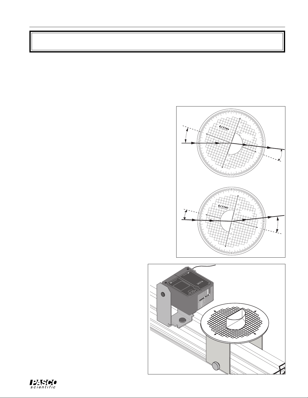
Procedure
Mount the Ray Table Base and the Light Source on the
Optics Bench.
1. Put the Ray Table on the base with the Cartesian grid
2. Put the Light Source on its bracket so that the mul-
3. For the first trial, put the Cylindrical Lens
See Figure 1.2
(mm SCALE) facing up. Turn the Ray Table so the 0
(zero) degree line points to the Light Source.
tiple slits are facing the Ray Table. Position the Light
Source so it is about two centimeters from the edge of
the Ray Table. Adjust the slit mask on the front of the
Light Source so the Light Source projects
one ray of light across the middle of the
top surface of the Ray Table.
on the Ray Table so the flat surface of the
lens faces the Light Source and the edge
of the lens is on the 90 (ninety) degree
line with the lens exactly centered on the
0 (zero) degree line.
SLITS
1
3
5
Angle of
Incidence
Figure 1.1
R
COLO
Y
A
R
BEFORE CHANGING BULB.
DISCONNECT POWER
WITH FINGERS.
DO NOT TOUCH BULB
BULB: 12V 10W G-4
INSTRUCTION MANUAL.
PASCO
scientific
TO REPLACE BULB SEE
80
70
90
60
50
40
30
20
10
0
40
0
30
1
20
0
2
SOURCE
LIGHT
B
O
A
S
S
-
8
I
C
5
1
O
7
P
T
I
C
S
12V @ 800mA
GENTLY SPREAD BRACKET.
TO REMOVE LIGHT SOURCE
20
10
3
40
50
0
6
70
80
90
POWER SUPPLY JACK
80
70
60
40
30
20
10
10
10
20
30
40
70
0
8
20
6
0
RAY TABLE
mm SCALE
30
50
40
40
30
5
0
4
0
30
20
1
0
0
1
0
2
0
Angle of
Refraction
2
Figure 1.2
3
Page 8

Optics Table 012-06557A
Record data.
Without disturbing the alignment of the Cylindrical Lens, rotate the Ray Table and set the angle of incidence to
the values listed in Table 1.1. Enter the corresponding angle of Refraction in the table in
two columns: Angle of
Refraction1 and Angle of Incidence2. (In other words, for the second trial, let Angle of Incidence2 be the value
you measured for Angle of Refraction1).
Ray Incident on: Flat Surface Curved Surface
Angle of: Incidence
0°
10°
20°
30°
40°
1
Refraction
1
Incidence
2
Refraction
2
50°
60°
70°
80°
Table 1.1 Data
For the second trail let the single ray from the Light Source strike the curved surface of the Cylindrical Lens.
(Just rotate the Ray Table 180°.) Start at 0 (zero) degrees. Rotate the Ray Table to each Angle of Incidence2 (the
values you listed in Table 1.1 as Angle of Refraction1). Record the corresponding values as the Angle of Refraction2.
1. Using your values for Incidence
and Refraction1, determine the index of refraction for the acrylic from which
1
the Cylindrical Lens is made. Remember, Snell’s Law describes the relationship between the angles of incidence and refraction and the indices of refraction:
n
sin Incidence1 = n
air
n
= ___________________________________________________________.
acrylic
2. Using your values for Incidence
sin Refraction1. (Assume that the index of refraction for air is 1.0.)
acrylic
and Refraction2, redetermine the index of refraction for the acrylic from which
2
the Cylindrical Lens is made.
n
= __________________________________________________________.
acrylic
3. Is the Law of Refraction the same for light rays going in either direction between the two media?
4. Does the principle of optical reversibility hold for Reflection as well as Refraction? Explain.
4
Page 9

012-06557A Optics Table
Experiment 2: Dispersion
EQUIPMENT NEEDED
– Cylindrical Lens – Ray Table
– Ray Table Base – Optics Bench
– Light Source – white paper
Procedure
Mount the Ray Table Base, Ray Table, Cylindrical Lens, and the Light Source on the Optics Bench.
1. Put the Ray Table on the base with the polar grid (DEGREE SCALE) facing up. Turn the Ray Table so the
0 (zero) degree line (NORMAL) points to the Light Source.
2. Set up the equipment as shown in Figure 2.1.
Adjust the slit mask on the Light Source so a
single light ray is incident on the curved surface of the Cylindrical Lens.
Record data
Set the Ray Table so the angle of incidence of the
single ray striking the flat surface of the lens
(from inside the lens) is zero-degrees. Hold a
piece of white paper against the edge of the Ray
Table so the refracted ray is visible on the piece
of paper.
5
R
O
L
SOURCE
O
C
LIGHT
BASIC OPTICS
Y
A
R
S
T
I
L
S
1
3
PA
SC
scientific
OS-8517
BEFORE CHANGING BULB.
DISCONNECT POWER
WITH FINGERS.
DO NOT TOUCH BULB
BULB: 12V 10W G-4
INSTRUCTION MANUAL.
TO REPLACE BULB SEE
GENTLY SPREAD BRACKET.
O
POWER SUPPLY JACK
12V @ 800mA
TO REMOVE LIGHT SOURCE
Slowly rotate the Ray Table to increase the angle
of incidence. As you do, watch the refracted ray
on the piece of paper.
1. At what angle of refraction do you begin to notice color separation in the refracted ray?
_____________________________________________________________________________.
Figure 2.1
2. At what angle of refraction is the color separation
a maximum?
_____________________________________________________________________________..
3. What colors are present in the refracted ray? (Write them in the order of minimum to maximum angle of refraction.)
4. Measure the index of refraction of acrylic for red and blue light:
(Remember, n
sin Incidence
air
air
= n
sin Refraction
acrylic
acrylic
)
Note: The index of refraction of a given material is usually expressed as a constant. However, different colors
of light refract to slightly different angles, and therefore have slightly different indices of refraction.
= __________________
n
red
n
= _________________
blue
5
Page 10

Optics Table 012-06557A
6
Page 11

012-06557A Optics Table
TO REPLACE BULB SEE
Experiment 3: Prism
EQUIPMENT NEEDED
– Light Source – Optics Bench
– Ray Table and Base – Rhombus
– white paper
Purpose
To show how a prism separates white light into its component colors and to show that different colors are refracted at different angles through a prism.
Theory
Snell’s Law states that the angle of refraction depends on the angle of incidence and the index of refraction of
the material. Because the index of refraction for light varies with the frequency of the light, white light which
enters the material at a given angle of incidence will separate out into its component colors as each frequency is
bent a different amount.
Procedure for Separating White Light
Mount the Light Source and the Ray Table Base on the
Optics Bench. Put the Ray Table on the base. Position the
Light Source near the edge of the Ray Table. Adjust the
slit mask on the Light Source so one light ray shines
across the middle of the top of the Ray Table.
Position the Rhombus on the Ray Table as shown in the
diagram. The triangular end of the Rhombus is used as a
prism in this experiment. Keep the light ray near the point
of the rhombus for maximum transmission of the light.
Rotate the rhombus until the angle (θ) of the emerging ray
is as large as possible and the ray separates into colors.
(a) What colors are seen and in what order are they?
(b) Which color is refracted at the largest angle?
INSTRUCTION MANUAL.
BULB: 12V 10W G-4
OS-8517
Ray Box
DO NOT TOUCH BULB
WITH FINGERS.
DISCONNECT POWER
BEFORE CHANGING BULB.
LIGHT
SOURCE
5 3 1
RAY
PATTERN
SLITS
COLOR
Rhombus
Single Ray
Normal to Surface
Color
θ
Figure 3
7
Page 12

Optics Table 012-06557A
BULB: 12V 10W G-4
SOURCE
DISCONNECT POWER
Experiment 4: Reflection – Plane and Curved Mirrors
EQUIPMENT NEEDED
– Light Source – Optics Bench
– Three-Surface Mirror – Drawing compass (SE-8733)
– metric rule – pencil
Purpose
To study how rays are reflected and to determine the focal
length and radius of curvature of different types of mirrors.
Part I: Plane Mirror
Procedure
Mount the Light Source and the Ray Table Base on the Optics Bench. Put the Ray Table on the base with the DEGREE
SCALE facing up. Position the Light Source near the edge of
the Ray Table. Adjust the slit mask on the Light Source so
one light ray shines across the middle of the top of the Ray
Table. Rotate the table so the light ray shines along the NORMAL line on the table.
DO NOT TOUCH BULB
WITH FINGERS.
DISCONNECT POWER
BEFORE CHANGING BULB.
LIGHT
SOURCE
5 3 1
RAY
PATTERN
SLITS
COLOR
Incident Ray
θ
i
Normal to surface
Figure 4.1
Place the Three-Surface mirror on the COMPONENT line on the Ray Table with the plane surface facing the
light source.
Rotate the Ray Table a few degrees. Measure the angle of incidence (θ
angles should be measured from the NORMAL line.
Change the angle of incidence and measure the incident and reflected angles again.
Part II: Cylindrical Mirrors
Theory
A concave cylindrical mirror will focus parallel rays of light at a focal point. The focal length is the distance
from the focal point to the center of the mirror surface. The radius of curvature of the mirror is twice the focal
length. See the diagram.
Procedure
Adjust the slit mask on the front of the Light Source so that five
light rays from the Light Source shine across the top of the Ray
Table. Rotate the table so the center light ray shines along the
NORMAL line. Turn the Three-Surface mirror so the concave
surface faces the Light Source and the center light ray shines on
the center of the curved surface.
Trace the outline of the mirror and trace the incident and reflected
rays. Indicate the incoming and the outgoing rays with arrows in
the appropriate directions.
) and the angle of reflection. Both these
i
5 3 1
SLITS
RAY
BEFORE CHANGING BULB.
PATTERN
COLOR
Figure 4.2
8
Page 13

012-06557A Optics Table
2
BULB: 12V 10W G-4
The place where the five reflected rays cross each other is the focal
point of the mirror. Measure the focal length from the center of the
concave mirror surface to the focal point. Use the compass to draw a
circle that matches the curvature of the mirror. Measure the radius of
curvature using a rule and compare it to the focal length.
R
f
Mirror
Repeat the procedure for the convex surface of the mirror. Note that
the reflected rays are diverging for a convex mirror and they will not
cross. After you trace the outline of the mirror and the incident and
reflected rays, use a rule to extend the reflected rays back behind the
mirror’s surface.
EQUIPMENT NEEDED
– Light Source – Optics Bench
– Ray Table and Base – Rhombus
– protractor – pencil
Purpose
To use Snell’s Law to determine the index of refraction of the
Acrylic rhombus.
Theory
Experiment 5: Snell’s Law
Focal Point
θ
Figure 4.3
Normal to surface
1
Snell’s Law states
where θ1 is the angle of incidence, θ2 is the angle of refraction,
and n1 and n2 are the respective indices of refraction of the materials.
Procedure
Mount the Light Source, Ray Table Base, and Ray Table on the
Optics Bench. Position the Light Box near the edge of the Ray
Table. Adjust the slit mask on the front of the Light Source so
that one light ray shines across the middle of the top of the Ray
Table.
Place the Rhombus on the center of the table and position it so
the single light ray passes through the parallel sides of the
Rhombus as shown in Figure 5.2. Use a pencil to trace the outline of the parallel surfaces of the Rhombus onto the Ray table.
Trace the incident and transmitted rays. Indicate the incoming
and the outgoing rays with arrows in the appropriate directions.
n1sinθ1= n2sinθ
n
1
n
2
Figure 5.1
DO NOT TOUCH BULB
WITH FINGERS.
DISCONNECT POWER
BEFORE CHANGING BULB.
LIGHT
SOURCE
5 3 1
RAY
PATTERN
SLITS
COLOR
θ
Normal to
Surface
θ
ι
Incident
Ray
Refracted Ray (n2 >
2
n1)
Rhombus
Figure 5.2
9
Page 14

Optics Table 012-06557A
SOURCE
DISCONNECT POWER
Remove the Rhombus and draw a line on the Ray Table connecting the points where the ray entered and left the
Rhombus.
Choose either the point where the ray enters the Rhombus or the point where the ray leaves the Rhombus. At
this point, draw the normal to the surface. Measure the angle of incidence (θ
) and the angle of refraction. Mea-
i
sure both angles from the normal.
Change the angle of incidence and measure the incident and refracted angles again.
Experiment 6: Total Internal Reflection
EQUIPMENT NEEDED
– Light Source – Optics Bench
– Ray Table and Base – Cylindrical Lens
– protractor – pencil
– white paper
Purpose
To determine the critical angle at which total internal reflection occurs.
Theory
Snell’s Law states that the angle of an incident light ray relative to the normal of a boundary between two substances is
related to the angle of the refracted light ray.
If a ray of light traveling from a medium of greater index of
refraction to a medium of lesser index of refraction is incident
with an angle greater than the critical angle (θ
refracted ray and total internal reflection occurs. If the angle of incidence is exactly the critical angle, the angle
of the refracted ray is 90 degrees. In this case, using Snell’s Law,
assuming the medium of lesser index of refraction is air with n2 = 1 and the medium of greater index of refraction is the acrylic Rhombus with n1 = n = 1.5. Solving for the critical angle gives
Procedure
), there is no
c
nsinθc= (1)sin(90°)
1
sinθc=
n
Air
n
Incident
Ray
Light Source
Normal to
θ
c
Figure 6.1
surface
Refracted
Ray
Reflected Ray
Mount the Light Source and Ray Table Base on the Optics
Bench. Put the Ray Table on the base with the DEGREE
SCALE facing up. Position the Light Box near the Ray Table.
Adjust the slit mask on the front of the Light Source so one light
ray shines across the across the top of the Ray Table. Turn the
Ray Table so the light ray shines along the NORMAL (zero
degrees) line of the table.
Place the Cylindrical Lens on the Ray Table so the curved side
of the lens faces the Light Source and the flat side of the lens is
on the COMPONENT line.
10
Incident
Ray
Reflected
Ray
Refracted
Ray
Figure 6.2
5 3 1
SLITS
RAY
BEFORE CHANGING BULB.
PATTERN
COLOR
Page 15

012-06557A Optics Table
Rotate the Ray Table until the light ray emerging from the Cylindrical
Exit point
Reflected Ray
Lens just barely disappears. Hold a piece of white paper next to the edge
of the Ray Table so you can see the light ray.
2θ
c
Just as it disappears, the ray separates into colors. The table is rotated far
enough if the red color has just disappeared.
Use the pencil to trace the edges of the Cylindrical Lens onto the Ray
Table. Mark the point on the table where the light ray is internally re-
Entrance point
Figure 6.3
Total Internal
Reflection
flected. Also mark the entrance point of the incident ray and the exit point
of the reflected ray.
Remove the Cylindrical Lens and draw the rays that are incident upon and reflect off the inside flat surface of
the Cylindrical Lens. Measure the total angle between these rays using a protractor. Note that this total angle is
twice the critical angle because the angle of incidence equals the angle of reflection.
Experiment 7: Refraction – Convex and Concave Lenses
EQUIPMENT NEEDED
– Light Source – Optics Bench
– Ray Table and Base – Convex Lens
– Concave Lens – ruler
Purpose
To explore the difference between convex and concave lenses and to determine their focal lengths.
Theory
Parallel rays of light passing through a thin convex lens cross at the focal point of the lens. The focal length is
measured from the center of the lens to the focal point.
Procedure
Mount the Light Source, Ray Table Base, and Ray Table on the Optics Bench. Place the Convex Lens on the
edge of the Ray Table nearest to the Light Source. Shine five light rays from the Light Source straight into the
convex lens. Trace the outline of the lens and trace the incident and transmitted rays. Indicate the incoming and
the outgoing rays with arrows in the appropriate directions.
The place where the five refracted rays cross each other is the
focal point of the lens. Measure the focal length from the center of the convex lens to the focal point.
Repeat the procedure for the concave lens. Put the concave
lens about two-thirds of the way across the Ray Table from the
Light Source. Note that the rays leaving the lens are diverging
and they will not cross. After you trace the outline of the lens
and the incident and refracted rays, use a ruler to extend the
outgoing rays straight back through the outline of the lens. The
focal point is where these extended rays cross.
Nest the convex and concave lenses together and place them in
the path of the parallel rays. Trace the rays. What does this tell
TO REPLACE BULB SEE
INSTRUCTION MANUAL.
BULB: 12V 10W G-4
DO NOT TOUCH BULB
WITH FINGERS.
OS-8517
LIGHT
5 3 1
SLITS
RAY
DISCONNECT POWER
BEFORE CHANGING BULB.
PATTERN
COLOR
SOURCE
Figure 7
Five parallel rays
Ray
Box
Double
Convex
Lens
11
Page 16
Optics Table 012-06557A
SOURCE
DISCONNECT POWER
you about the relationship between the focal lengths of these two lenses?
Slide the convex and concave lenses apart to observe the effect of a combination of two lenses. Then reverse the
order of the lenses. Trace the patterns.
Place the convex lens in the path of the five light rays. Put a finger in front of the slit mask to block out the
center three rays and mark the focal point for the outer two rays. Next, adjust the slit mask on the fron t of the
Light Source so three light rays shine across the middle of the Ray Table and mark the focal point for the three
rays. Are the two focal points the same?
Experiment 8: Lensmaker’s Equation
EQUIPMENT NEEDED
– Light Source – Optics Bench
– Ray Table and Base – Concave lens
– metric ruler – pencil
Purpose
To determine the focal length of a convex
lens by direct measurement and by using
the lensmaker’s equation.
Theory
The lensmaker’s equation is used to calculate the focal length of a lens based on the
radii of curvature of its surfaces and the
index of refraction of the lens material.
1
1
=(n–1)
f
1
+
R
R
1
2
where f is the focal length, n is the relative
index of refraction of the lens material, and
R1 and R2 are the radii of curvature of the
lens surfaces.
➤NOTE: In this notation, R is positive for a
convex surface (as viewed from outside the lens) and R is negative for a
concave surface.
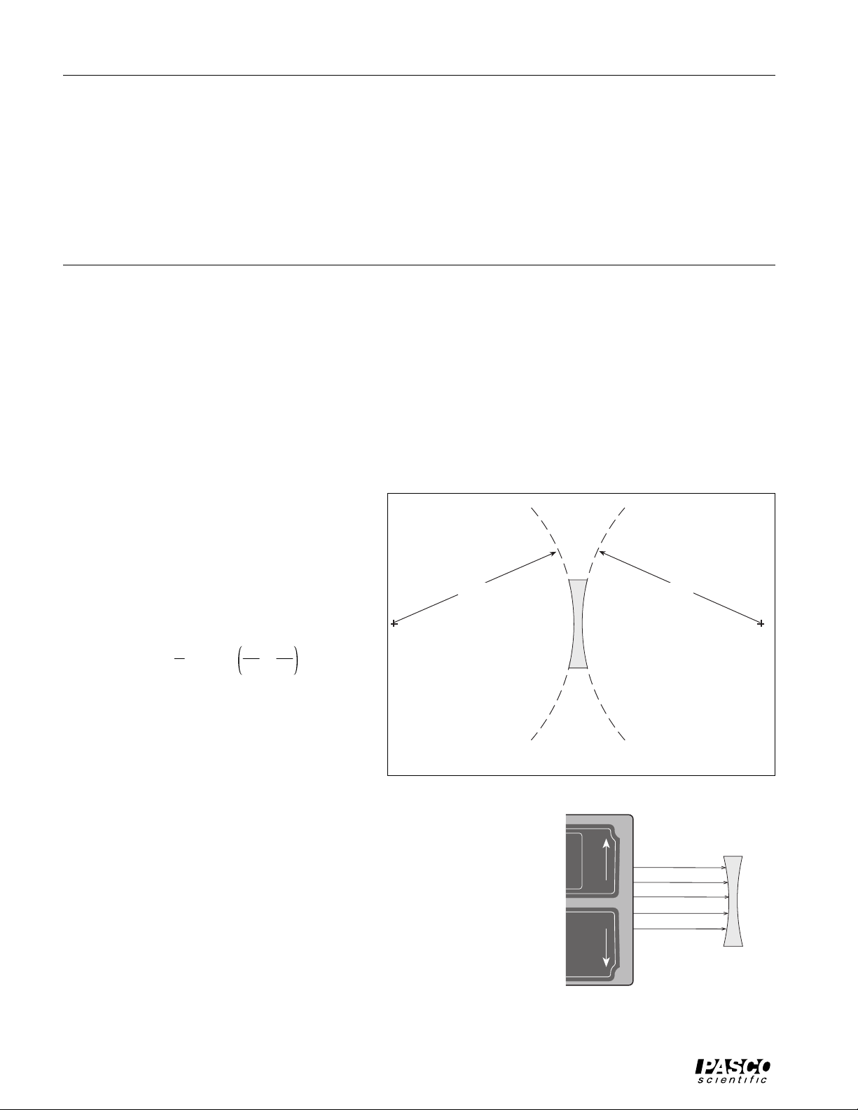
Procedure
Mount the Light Source, Ray Table Base, and Ray Table on the Optics
Bench. Place the Concave Lens on the Ray Table. Shine five light rays
from the Light Source straight into the lens. Trace the outline of the lens
and trace the incident and transmitted rays. Indicate the incoming and
the outgoing rays with arrows in the appropriate directions.
R
1
Figure 8.1
Double
Concave
Lens
Light Source
5 3 1
SLITS
RAY
BEFORE CHANGING BULB.
PATTERN
COLOR
R
2
Concave Lens
Five parallel
rays
Figure 8.2
12
Page 17

012-06557A Optics Table
Remove the lens. To measure the focal length, use a ruler to extend the
outgoing diverging rays straight back through the outline of the lens.
The focal point is where these extended rays cross. Measure the distance from the center of the lens to the focal point.
Light
5 3 1
SLITS
RAY
Source
Incident rays
Concave
Lens
1/2 R
To determine the radius of curvature, put the concave lens back in the
path of the rays and observe the faint reflected rays off the first surface
of the lens. (The front of the lens can be treated as a concave mirror
having a radius of curvature equal to twice the focal length of the effec-
PATTERN
COLOR
tive mirror.) Trace the incident rays and the faint reflected rays. Measure the distance from the center of the front curved surface to the point
where the faint reflected rays cross. The radius of curvature of the surface is twice this distance.
Faint Reflected
Rays
Figure 8.3
Note that the lens is symmetrical and it is not necessary to measure the
curvature of both sides of the lens because R is the same for both. Calculate the focal length of the lens using
the lensmaker’s equation. The index of refraction is 1.5 for the lens. Remember that a concave surface has a
negative radius of curvature.
Experiment 9: Apparent Depth
EQUIPMENT NEEDED
– Light Source – Optics Bench
– Convex lens – Rhombus
– masking tape – metric ruler– pencil
PART I
Purpose
To determine the index of refraction using apparent depth.
Theory
Light rays originating from the bottom surface of a block of material
refract at the top surface as the rays emerge from the material into the
air. When viewed from above, the apparent depth, d, of the bottom
surface of the block is less than the actual thickness, t, of the block.
The apparent depth is given by
d = t/n, where n is the index of refraction of the material.
Procedure
Mount the Light Source, Ray Table Base, and Ray Table on the Optics Bench. Place the Convex Lens on the
edge of the Ray Table nearest to the Light Source. Adjust the slit mask on the front of the Light Source so five
light rays shine straight into the Convex Lens. Use a strip of masking tape to block the center three light rays.
Air
n
d
t
Figure 9.1
Mark the place where the two outer light rays cross each other.
Next, place the Rhombus as shown in Figure 9.2. The surface of the Rhombus facing the Light Source must be
exactly at the point where the two rays cross. The crossed rays simulate the rays that emerge from the bottom of
the Rhombus block discussed in the theory.
13
Page 18

Optics Table 012-06557A
Trace the outline of the of the Rhombus and trace the rays diverging from the
surface facing away from the Light Source.
Remove the Rhombus, turn off the light source, and trace the diverging rays
back into the outline of the Rhombus. The place where these rays cross (in-
d
t
side the outline of the Rhombus) is the apparent position of the “bottom” of
the Rhombus when viewed from the “top”.
Rhombus
Measure the apparent depth, d, and the thickness, t. Calculate the index of
refraction of the material using n = t/d. Compare the measured value to the
accepted value (n = 1.5).
Convex
Lens
PART II
Theory
Parallel rays passing through a Convex Lens cross at the focal point of the
Light Source
lens.If a block with parallel sides is placed between the lens and the focal
point, the point where the rays cross moves further from the lens.Since the
thickness, t, of the block has an apparent depth, d, that is less than the thickness (d = t/n), the point where the rays cross must move by an amount equal
to the difference between the actual thickness of the block and the apparent
thickness of the block. Thus the distance, x, that the focal point moves is given by x = t - t/n, where n is the
index of refraction of the block.
Figure 9.2
Procedure
Mark the place where the two light rays
cross. Place the Rhombus between the
lens and the place where the rays cross.
Mark the new place where the rays cross.
Move the Rhombus to a new position,
closer to the lens. Does the position of the
focal point change?
Turn off the light source and measure the
distance, x, between the marks.
Using the thickness, t, of the Rhombus
from Part I and the distance x, calculate
the index of refraction using
n =
value to the accepted value (n = 1.5).
1–
5 3 1
SLITS
RAY
PATTERN
COLOR
1
x
Compare the measured
Light
Source
Lens
Rhombus
Figure 9.3
New focus
with Rhombus
in place
Focus without
Rhombus
t
14
Page 19

012-06557A Optics Table
T eacher’s Guide
Experiment 1: Reversibility
Suggestions on Procedure
For best results, make sure that the Cylindrical Lens is aligned exactly with the Ray Table.
The index of refraction is equal to the slope of the “Refraction 1” graph. n = 1.498
The slope of data set 2 is 1/n. Thus, n = 1.501.
Yes, the Law of Refraction is the same for light rays going in either direction between the two media..
Yes, the principle of optical reversibility holds for reflection as well as refraction.. The angle of incidence
equals the angle of reflection regardless of which side the light is coming from.
Angle of:
Incidence1 Refraction1 Incidence2 Refraction2
0 0.0 0.0 1.0
10 7.0 7.0 7.5
20 13.5 13.5 19.5
30 20.0 20.0 30.0
40 25.5 25.5 39.0
50 31.0 31.0 49.0
60 35.5 35.5 59.0
70 39.5 39.5 70.0
80 41.0 41.0 77.0
Experiment 2: Dispersion
Color separation was first noted at about 40°, although it may be noticeable before then depending on the light
in the room.
Maximum separation occurs at about 85°; beyond that the violet is totally internally reflected.
In order: (although not all colors may be resolvable depending on the room light) red, orange, yellow, green,
cyan, blue, violet.
With an incident angle of 40°, the violet was at 76° and the red was at 73°.
1
0.9
0.8
0.7
slope = 1.498
0.6
0.5
0.4
0.3
Sin(angle of incidence)
0.2
0.1
5
2
5
0
2
0 0.1 0.2 0.3 0.4 0.5 0.6 0.7 0.8 0.9 1
5
5
5
2
Sin(angle of refraction)
5
5
5
5
2
2
slope = 0.6662
1/slope = 1.501
5
Refraction 1
Refraction 2
2
2
2
2
2
n
= 1.488
red
n
= 1.510
violet
Experiments 3 through 9
Please refer to the Instruction Manual and Experiment Guide for the OS-8515 Basic Optics System.
15
Page 20

Optics Table 012-06557A
Notes
16
Page 21

012-06557A Optics Table
T echnical Support
Feedback
If you have any comments about the product or manual,
please let us know. If you have any suggestions on
alternate experiments or find a problem in the manual,
please tell us. PASCO appreciates any customer feedback. Your input helps us evaluate and improve our
product.
To Reach PASCO
For technical support, call us at 1-800-772-8700 (toll-free
within the U.S.) or (916) 786-3800.
fax: (916) 786-3292
e-mail: techsupp@pasco.com
web: www.pasco.com
Contacting Technical Support
Before you call the PASCO Technical Support staff, it
would be helpful to prepare the following information:
• If your problem is with the PASCO apparatus, note:
Title and model number (usually listed on the
label);
Approximate age of apparatus;
A detailed description of the problem/sequence of
events (in case you can’t call PASCO right away,
you won’t lose valuable data);
If possible, have the apparatus within reach when
calling to facilitate description of individual parts.
• If your problem relates to the instruction manual, note:
Part number and revision (listed by month and year
on the front cover);
Have the manual at hand to discuss your
questions.
17
Page 22

 Loading...