

Page 1
Instruction Manual for
the PASCO scientific
Model OS-8535
LINEAR TRANSLATOR
FOR THE BASIC OPTICS SYSTEM
012-06551A
1/98
© 1998 PASCO scientific $10.00
Page 2

Page 3

012-06551A Basic Optics Linear Translator
T able of Contents
Section Page
Copyright, Warranty, and Equipment Return .....................................................ii
Description .......................................................................................................1
Mounting the Translator on the Optics Bench ....................................................1
Using a Rotary Motion Sensor .......................................................................... 2
Using the Rack Separately.................................................................................3
Suggestions for Using the Linear Translator ......................................................4
Set Up for a Diffraction Pattern Experiment ......................................................5
Technical Support ......................................................................... Inside Back Cover
i
Page 4

Basic Optics Linear Translator 012-06551A
Copyright, Warranty and Equipment Return
Please—Feel free to duplicate this manual
subject to the copyright restrictions below.
Copyright Notice
The PASCO scientific Model OS-8535 Linear Translator
manual is copyrighted and all rights reserved. However,
permission is granted to non-profit educational institutions for reproduction of any part of this manual providing the reproductions are used only for their laboratories
and are not sold for profit. Reproduction under any other
circumstances, without the written consent of PASCO
scientific, is prohibited.
Limited Warranty
PASCO scientific warrants this product to be free from
defects in materials and workmanship for a period of one
year from the date of shipment to the customer. PASCO
will repair or replace, at its option, any part of the product
which is deemed to be defective in material or workmanship. This warranty does not cover damage to the product
caused by abuse or improper use. Determination of
whether a product failure is the result of a manufacturing
defect or improper use by the customer shall be made
solely by PASCO scientific. Responsibility for the return
of equipment for warranty repair belongs to the customer.
Equipment must be properly packed to prevent damage
and shipped postage or freight prepaid. (Damage caused
by improper packing of the equipment for return shipment will not be covered by the warranty.) Shipping costs
for returning the equipment, after repair, will be paid by
PASCO scientific.
Equipment Return
Should this product have to be returned to PASCO
scientific, for whatever reason, notify PASCO scientific
by letter or phone BEFORE returning the product. Upon
notification, the return authorization and shipping instructions will be promptly issued.
➤ NOTE:
NO EQUIPMENT WILL BE ACCEPTED FOR
RETURN WITHOUT AN AUTHORIZATION.
When returning equipment for repair, the units must be
packed properly. Carriers will not accept responsibility
for damage caused by improper packing. To be certain
the unit will not be damaged in shipment, observe the
following rules:
➀ The carton must be strong enough for the item
shipped.
➁ Make certain there is at least two inches of packing
material between any point on the apparatus and the
inside walls of the carton.
➂ Make certain that the packing material can not shift in
the box, or become compressed, thus letting the instrument come in contact with the edge of the box.
Address: PASCO scientific
10101 Foothills Blvd.
Credits
This manual authored by: Dave Griffith
P.O. Box 619011
Roseville, CA 95678-9011
Phone: (916) 786-3800
FAX: (916) 786-8905
ii
Page 5
012-06551A Basic Optics Linear Translator
Introduction
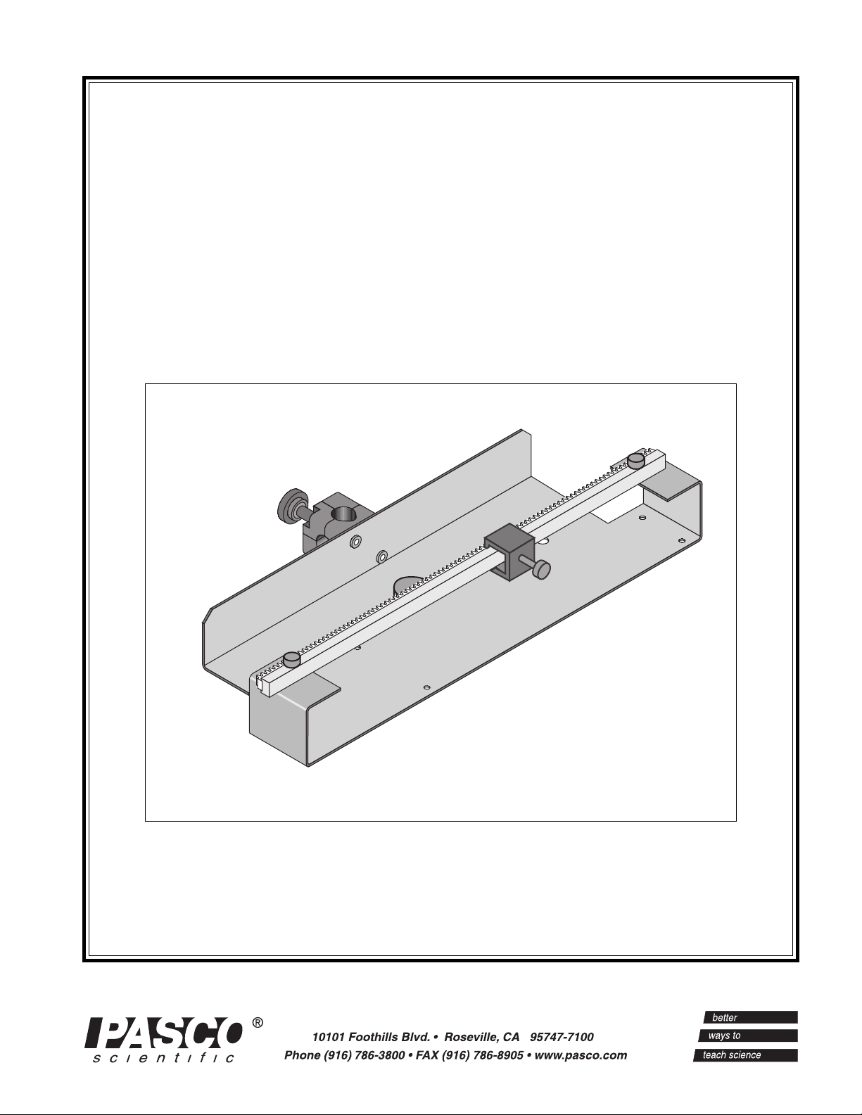
The PASCO OS-8535 Linear Translator is designed to be mounted on the Optics Bench of the OS-8515 Basic Optics
System. The Linear Translator can also be mounted on a rod up to 0.5 inch (12 mm) diameter.
Description
The Linear Translator consists of a base with mounting hardware and an attached rod clamp, a rack, and a rack clamp.
The hole in the base allows it to be stored on a peg. The mounting hardware on the base consists of a thumbscrew and a
square nut. The nut fits into the T-slot in the center of the Optics Bench (part of the OS-8515).
The rack is attached to the top of the base with two thumbscrews. The rack is designed to fit inside the T-slot on the side
the PASCO Model CI-6538 Rotary Motion Sensor (or CI-6625 Rotary Motion Sensor for ULI). The teeth on the rack
engage a gear inside the Rotary Motion Sensor, causing the gear to rotate when the Rotary Motion Sensor moves along
the rack. The Rotary Motion Sensor measures its linear position along the rack.
The rack clamp is attached to the back of the rack with a thumbscrew. The clamp sets the initial or final position of the
Rotary Motion Sensor.
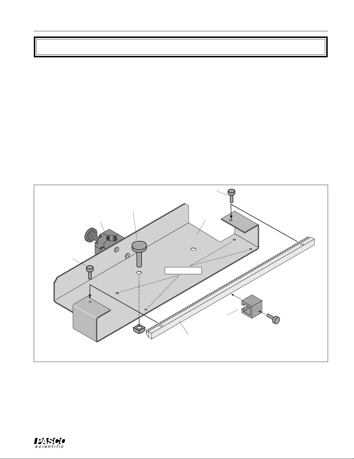
rack
thumbscrew
rod clamp
rack
thumbscrew
base thumbscrew
base
alignment studs
rack clamp
rack
square nut
Figure 1: Linear Translator for Basic Optics
Mounting the Linear Translator on the Optics Bench
You can mount the Linear Translator on the Optics Bench in two ways: with the Rack perpendicular to the Optics
Bench or with the Rack parallel to the Optics Bench.
1
Page 6

Basic Optics Linear Translator 012-06551A
Pependicular Mount
To mount the Linear Translator so the Rack is perpendicular,
leave the mounting hardware (thumbscrew and square nut) in
the center hole. Loosen the thumbscrew by turning the thumbscrew counter-clockwise while holding the square nut. Leave
the square nut on the end of the thumbscrew.
Attach the base to the Optics Bench by inserting the square nut
into the T-slot located along the center of the Optics Bench.
Use the two widely spaced alignment studs on the underside of
the base to align the Linear Translator with the edge of the Optics Bench.
The Linear Translator can be moved to any position along the
Optics Bench while the thumbscrew is loose. Tighten the
The alignment studs rest against the
edge of the Optics Bench
Figure 2: Linear Translator on Optics Bench
thumbscrew to secure the Linear Translator in position.
Parallel Mount
To mount the Linear Translator so the Rack is parallel to
the Optics Bench, move the mounting hardware from the
center hole to the off-center hole (see Figure 3.1).
Turn the Linear Translator so the Rack is parallel to the
Optics Bench. Insert the square nut into the T-slot located along the center of the Optics Bench.
Using a Rotary Motion Sensor
You can mount a PASCO Model CI-6538 Rotary Motion Sensor or the Model CI-6625 Rotary Motion Sensor
for ULI on the rack of the Linear Translator.
The Rotary Motion Sensor has a T-slot into which
you can slide the Rack of the Linear Translator. The
first step is to remove the rack thumbscrews from the
ends of the Rack. Turn the thumbscrews counterclockwise to remove them.
You may also want to remove the Rack Clamp from
the Rack. Turn the rack thumbscrew counter-clockwise until you can slide the Rack Clamp off the end
of the Rack.
Move the mounting hardware to
the off-center hole.
Slide the square nut
into the T-slot.
Figure 3.1
If you are using the three-step pulley on the Rotary
Motion Sensor, hold the Rotary Motion Sensor so the
three-step pulley is on top. Line up the Rack with the
T-slot on the side of the Rotary Motion Sensor. The
teeth on the Rack go through the narrow side of the
T-slot and then engage a gear that is on the shaft of
the Rotary Motion Sensor. Gently push the Rack
through the T-Slot and into the sensor.
The alignment studs rest against
the edge of the Optics Bench.
Figure 3.2: Linear Translator Parallel to Optics Bench
2
Page 7

012-06551A Basic Optics Linear Translator
When the Rack is in the T-slot, put the Rack
Clamp back onto the Rack and tighten its
thumbscrew. Place the Rack with the sensor
back onto the Linear Translator. The back end
Rotary Motion Sensor
of the Rotary Motion Sensor rests on the upright edge of the base of the Linear Translator.
Line up the holes in the ends of the Rack with
the holes on the Linear Translator base. Put the
thumbscrews into the holes and turn them
rack
rack thumbscrew
clockwise to tighten.
If the Linear Translator is mounted parallel to
the Optics Bench, move the rod clamp from the
rack
clamp
end of the Rotary Motion Sensor to the side of
the Rotary Motion Sensor. By doing this, the
Light Sensor will be along the center line of the
Optics Bench when you put the Aperture
Bracket post into the rod clamp of the Rotary
Linear Translator
Motion Sensor.
You will need a Phillips head screwdriver with
a small tip (e.g., #0). Use the screwdriver to remove the two screws from the end of the rod
clamp. Align the rod clamp with the threaded
Figure 4.1: Rotary Motion Sensor onto Linear Translator
holes on the side of the Rotary Motion Sensor.
Replace the screws.
Move the rod clamp to the side
Using the Rack Separately
of the Rotary Motion Sensor
and replace the screws.
The rack of the Linear Translator can be used separately from the Linear Translator. For example, it can
be an accessory to the Rotary Motion Sensor in experiments that do not require the Optics Bench but that do
require the measurement of linear position.
rod clamp
Remove the two rack thumbscrews. Remove the rack
clamp from the rack. Use a Phillips head screwdriver
with a small tipe (e.g., #0) to remove the two screws
from the end of the rod clamp that is on the Linear
Translator. Use one of the rack thumbscrews to attach
the rod clamp to one end of the rack as shown. Use the
rod clamp to hold sensors, etc.
rack
rack thumbscrew
Figure 5: Rod Clamp attached to Rack
rod clamp
Remove the
screws from the
rod clamp.
Optics Bench
Figure 4.2: Rotary Motion Sensor on Linear Translator
Parallel to Optics Bench
3
Page 8

Basic Optics Linear Translator 012-06551A
Suggestions for Using the Linear Translator
Light Intensity of Diffraction Patterns
EQUIPMENT NEEDED
– Optics Bench (part of OS-8515) – Linear Translator (OS-8535)
– Aperture Bracket (OS-8534) – Slit Accessory (OS-8523)
– Diode Laser (OS-8525) – Rotary Motion Sensor (CI-6538)
– Light Sensor (CI-6504A)
Use the Diode Laser and Slit Accessory to produce a diffraction pattern. Mount the Linear Translator on the
Optics Bench so the rack is perpendicular to the Optics Bench. Use the Light Sensor to measure the intensity of
light in the diffraction pattern. Use the Rotary Motion Sensor mounted on the Linear Translator to measure the
position of the Light Sensor as it moves through the diffraction pattern.
Light Sensor on Aperture Bracket
Slit Accessory
Rotary Motion Sensor
Optics Bench
Linear Translator
Figure 6: Light Intensity of Diffraction Patterns
Diode Laser
(The description for this experiment starts on the next page.)
Light Intensity versus Distance
EQUIPMENT NEEDED
– Optics Bench (part of OS-8515) – Linear Translator (OS-8535)
– Aperture Bracket (OS-8534) – Light Source (part of OS-8515)
– Rotary Motion Sensor (CI-6538) – Light Sensor (CI-6504A)
Use the Light Source to produce a “point source” of light. Mount the Linear Translator on the Optics Bench so the
rack is parallel to the Optics Bench. Use the Light Sensor to measure the intensity of the light. Use the Rotary
Motion Sensor mounted on the Linear Translator to measure the position of the Light Sensor as it moves relative
to the Light Source.
Light Source
Linear Translator
Light Sensor on
Aperture Bracket
4
Rotary Motion
Sensor
Figure 7: Light Intensity versus Distance
Optics Bench
Page 9
012-06551A Basic Optics Linear Translator
LIGHT
SENSOR
Set Up for a Diffraction Pattern Experiment
EQUIPMENT NEEDED
– Optics Bench (part of OS-8515) – Linear Translator (OS-8535)
– Aperture Bracket (OS-8534) – Slit Accessory (OS-8523)
– Diode Laser (OS-8525) – Rotary Motion Sensor (CI-6538)
– Light Sensor (CI-6504A)
Introduction
The purpose is to investigate the wave nature of light. A Light Sensor measures the intensity of the interference
pattern created by monochromatic laser light passing through a single or multiple slit. The Rotary Motion Sensor mounted on the Linear Translator measures the relative positions of the maxima in the pattern.
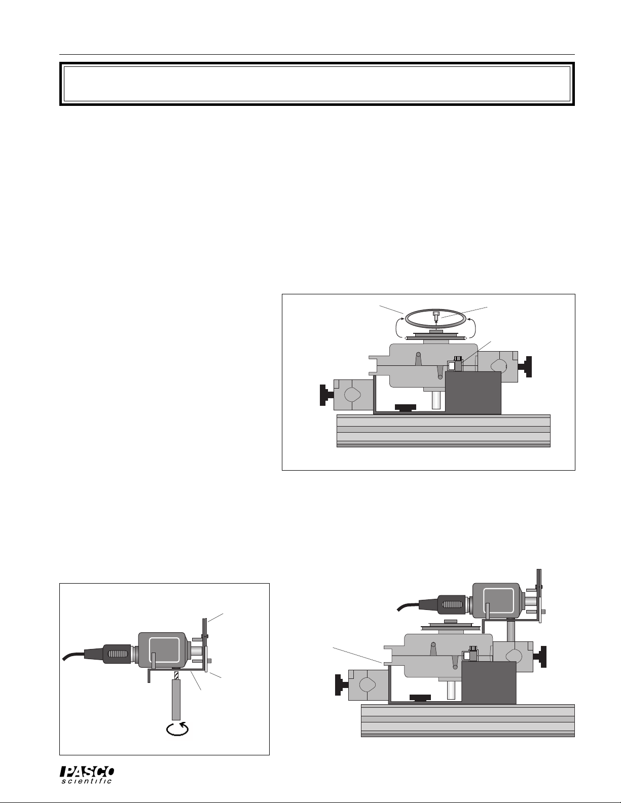
Procedure
1. Put the Linear Translator onto the Optics Bench so the rack is perpendicular
remove “O” ring remove thumbscrew
to the Optics Bench. Mount the Rotary
Motion Sensor onto the Rack of the
Rotary Motion Sensor
rack
Linear Translator as described in the
Introduction. Remove the “O” ring and
thumbscrew from the Rotary Motion
Sensor pulley as shown in Figure 1 so
they will not interfere with the Aperture
Linear Translator
Bracket.
2. Mount the Light Sensor onto the Aper-
Optics Bench
ture Bracket by screwing the Aperture
Bracket post into the threaded hole on
Figure 1
the bottom of the Light Sensor as
shown.
3. Put the post into the rod clamp on the end of the Rotary Motion Sensor. Lower the Aperture Bracket until it
rests on the top of the Rotary Motion Sensor. Tighten the Rod Clamp thumbscrew to hold the Aperture Bracket
and Light Sensor in place.
Light Sensor and
Aperture Bracket
cable to
interface
cable to
interface
Light
Sensor
LIGHT
SENSOR
post
Aperture
Bracket
aperture
disk
screen
Rotary Motion Sensor
rests on the edge of the
Linear Translator
Figure 2
Optics Bench
Figure 3
5
Page 10

Basic Optics Linear Translator 012-06551A
4. Mount the Diode Laser and a Slit Accessory at the other end of the Optics
Bench. For example, put the MULTIPLE SLIT SET into the Slit Acces-
Slit Accessory Diode Laser
sory holder.
5. Plug in the power supply for the Diode
Laser. Turn on the laser.
thumbscrew
6. Rotate the SLIT SET disk on the Slit
Accessory until a slit pattern is in line
with the laser beam. Use the adjustment
screws on the back of the Diode Laser
to adjust the beam if necessary.
Optics Bench
Figure 4
7. Rotate the pulley on the top of the Rotary Motion Sensor to move it along the rack on the
Linear Translator. Move the Rotary Motion/Light Sensor until the white screen on the front of the Aperture
Bracket shows the diffraction pattern.
8. Examine the diffraction pattern on the white screen. If
the pattern is not horizontal, loosen the thumbscrew on
the Slit Accessory. Slowly rotate the Slit Accessory
until the laser beam is centered on the slit pattern you
want and the diffraction pattern is horizontal on the
white screen on the Aperture Bracket. Tighten the
thumbscrew on the Slit Accessory to hold it in place.
laser beam
slit pattern
thumbscrew
S
T
I
L
S
E
L
B
U
O
4
0
0
D
.
5
.
0
0
4
5
0
2
m
.
.
0
0
m
m
:
:
n
i
=
m
=
d
n
a
n
o
i
i
t
h
a
t
r
d
a
i
p
w
e
t
5
i
s
l
t
s
i
l
:
s
=
:
a
=
d
S
T
I
L
V
A
R
I
A
a
d
=
8
0
0
.
.
0
5
.
0
OS-8523
5
6
8
5
0
-
BASIC OPTICS
SLIT ACCESSORY
=
d
4
0
.
0
=
a
3
2
T
L
U
M
1
a= 0.04 0.04
d= 0.125 0.125
0
8
0
.
5
2
0
.
0
MULTIPLE SLIT SET
6
4
6
5
2
1
.
0
4
S
E
L
P
I
Slit Accessory
B
L
E
D
O
U
B
L
E
S
=
L
0
.
0
I
2
4
T
5
t
o
0
.
7
5
a= 0.040.04
d= 0.25
a= 0.040.04
d= 0.250.50
C
a
O
=
d
0
.0
=
4
M
0
.2
0
5
.08
P
0
.2
5
A
R
I
S
O
N
S
9. Rotate the Aperture Disk on the front of the Aperture
Bracket until the narrowest slit opening is in front of
Figure 5
the Light Sensor opening. This reduces the amount of
ambient light that can enter the Light Sensor while the Light
Sensor is between maxima of the diffraction pattern.
Slit Disk
10.Move the Rotary Motion Sensor/Light Sensor along the rack
on the Linear Translator until the center of the difffraction
pattern is aligned with the center of the narrow slit on the
Aperture Disk of the Aperture Bracket. Loosen the Rotary
Motion Sensor rod clamp and adjust the Aperture Bracket and
Light Sensor up or down if necessary.
diffraction pattern
white screen
Figure 6
Data Recording
Refer to Physics Labs with Computers, Volume 2, (PASCO Model CI-7010) for information about data recording using a ScienceWorkshop interface.
6
Page 11

012-06551A Basic Optics Linear Translator
T echnical Support
Feedback
If you have any comments about the product or
manual, please let us know. If you have any suggestions on alternate experiments or find a problem in the
manual, please tell us. PASCO appreciates all customer feedback. Your input helps us evaluate and
improve our product.
To Reach PASCO
For technical support, call us at 1-800-772-8700 (tollfree within the U.S.) or (916) 786-3800.
fax: (916) 786-3292
e-mail: techsupp@pasco.com
web: www.pasco.com
Contacting Technical Support
Before you call the PASCO Technical Support staff, it
would be helpful to prepare the following information:
• If your problem is with the PASCO apparatus, note:
Name and model number (usually listed on the
label);
Approximate age of apparatus;
A detailed description of the problem/sequence of
events (in case you can’t call PASCO right away,
you won’t lose valuable data);
If possible, have the apparatus within reach when
calling to facilitate description of individual parts.
• If your problem relates to the instruction manual,
note:
Part number and revision (listed by month and
year on the front cover);
Have the manual at hand to discuss your questions.
7
Page 12

 Loading...