

Page 1
Instruction Manual and
012-09200A
Experiment Guide for
the PASCO scientific
Model OS-8533A
POLARIZATION ANALYZER
Light Sensor
(not included)
Polarization
Analyzer
© 2005 PASCO scientific
Aperture
Bracket
Page 2

012-09200A Polarization Analyzer
Table of Contents
Section Page
Copyright, Warranty, and Equipment Return.....................................................ii
Description .......................................................................................................1
Mounting a Rotary Motion Sensor ....................................................................1
Using the Rotary Motion Sensor ....................................................................... 3
Mounting a Light Sensor...................................................................................3
Setup for Measuring Light Intensity ..................................................................4
Verify Malus’ Law of Polarization ....................................................................5
Teacher’s Guide................................................................................................9
Technical Support ......................................................................... Inside Back Cover
i
Page 3

Polarization Analyzer 012-09200A
Copyright, Warranty, and Equipment Return
Please—Feel free to duplicate this manual
subject to the copyright restrictions below.
Copyright Notice
The PASCO scientific 012-09200 Model OS-8533A
Polarization Analyzer is copyrighted and all rights
reserved. However, permission is granted to non-profit
educational institutions for reproduction of any part of the
manual providing the reproductions are used only for
their laboratories and are not sold for profit. Reproduction
under any other circumstances, without the written
consent of PASCO scientific, is prohibited.
Limited Warranty
PASCO scientific warrants the product to be free from
defects in materials and workmanship for a period of one
year from the date of shipment to the customer. PASCO
will repair or replace at its option any part of the product
which is deemed to be defective in material or workmanship. The warranty does not cover damage to the product
caused by abuse or improper use. Determination of
whether a product failure is the result of a manufacturing
defect or improper use by the customer shall be made
solely by PASCO scientific. Responsibility for the return
of equipment for warranty repair belongs to the customer.
Equipment must be properly packed to prevent damage
and shipped postage or freight prepaid. (Damage caused
by improper packing of the equipment for return shipment will not be covered by the warranty.) Shipping costs
for returning the equipment after repair will be paid by
PASCO scientific.
Equipment Return
Equipment Return
Should the product have to be returned to PASCO
scientific for any reason, notify PASCO scientific by
letter, phone, or fax BEFORE returning the product.
Upon notification, the return authorization and
shipping instructions will be promptly issued.
➤ ➤
➤ NOTE: NO EQUIPMENT WILL BE
➤ ➤
ACCEPTED FOR RETURN WITHOUT AN
AUTHORIZATION FROM PASCO.
When returning equipment for repair, the units must
be packed properly. Carriers will not accept responsibility for damage caused by improper packing. To be
certain the unit will not be damaged in shipment,
observe the following rules:
➀ The packing carton must be strong enough for the
item shipped.
➁ Make certain there are at least two inches of
packing material between any point on the apparatus and the inside walls of the carton.
➂ Make certain that the packing material cannot shift
in the box or become compressed, allowing the
instrument come in contact with the packing
carton.
Address: PASCO scientific
10101 Foothills Blvd.
Roseville, CA 95747-7100
Should the product have to be returned to PASCO
scientific for any reason, notify PASCO scientific by
letter, phone, or fax BEFORE returning the product.
Upon notification, the return authorization and shipping
instructions will be promptly issued.
Credits
This manual authored by: Dave Griffith
Phone: (916) 786-3800
FAX: (916) 786-3292
email: techsupp@pasco.com
web: www.pasco.com
ii
Page 4
012-09200A Polarization Analyzer
Introduction
The PASCO OS-8533A Polarization Analyzer is designed to be mounted on the Optics Bench of the OS-8515
Basic Optics System and to be used with the Basic Optics Light Source (part of the OS-8515 Basic Optics System) and a Light Sensor such as the PASCO CI-6504A, or PS-2106 to explore polarization. When used with the
PASCO CI-6538 or PS-2120 Rotary Motion Sensor, you can measure the relationship between the light intensity transmitted through a set of polarizers and the angle of the polarizers.
Recommended Equipment
Basic Optics System (OS-8515) Light Sensor (CI-6504A or PS-2106)
Rotary Motion Sensor (CI-6538, or PS-2120)
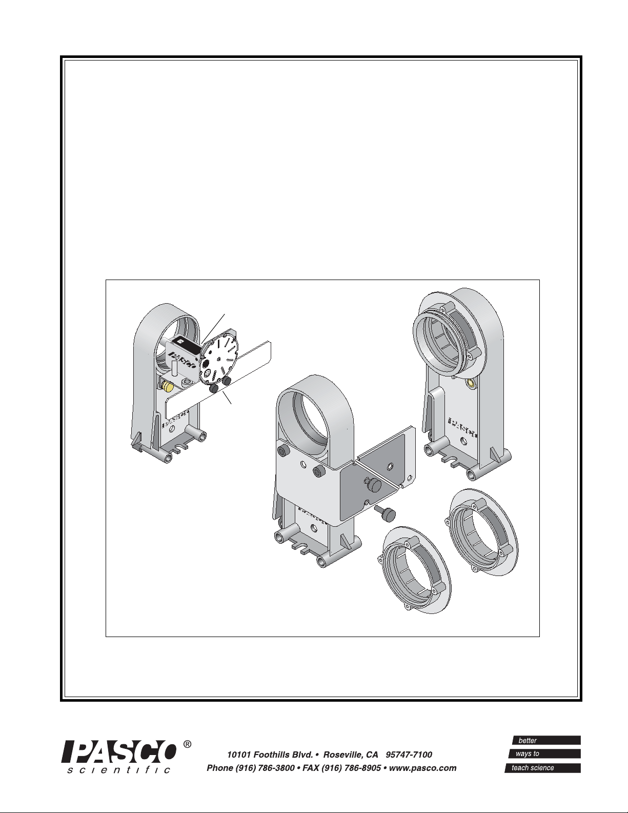
Description
The Polarization Analyzer consists of a Polarizer Holder, an Accessory Holder with
Mounting Bracket, two Polarizers, a Retarder
and an Aperature Bracket. The mounting
bracket is permanently attached to the Accessory Holder. The mounting bracket holds a
Rotary Motion Sensor in position to measure
the angle of one Polarizer as it turns relative
to the other Polarizer. The mounting bracket
includes two thumbscrews and a plastic belt.
The thumbscrews attach the Rotary Motion
Sensor to the bracket. The plastic belt is used
with a Rotary Motion Sensor.
The Polarizers and Retarder snap into the
opening at the top of the Accessory Holder
or the Polarizer Holder. The Retarder is a
one-quarter wavelength (140 nanometer) retarder. Each Polarizer has an angular scale
near its outside edge marked in ten degree
increments with additional marks at 45, 135,
225, and 315 degrees.
Polarizer with
Groove
Accessory Holder with
Mounting Bracket
thumbscrew
storage holes
Figure 1: Polarization Analyzer Components
Polarizer Holder
plastic belt
thumbscrews
Polarizer
Retarder
One of the Polarizers has a groove on its front edge. Use
this Polarizer with the Accessory Holder. When the Rotary Motion Sensor is mounted on the Accessory Holder
bracket, you can put the plastic belt over the groove on the
front of the Polarizer and a groove on the three-step pulley on
the Rotary Motion Sensor. This allows you to measure the
angular position of the Polarizer as it turns.
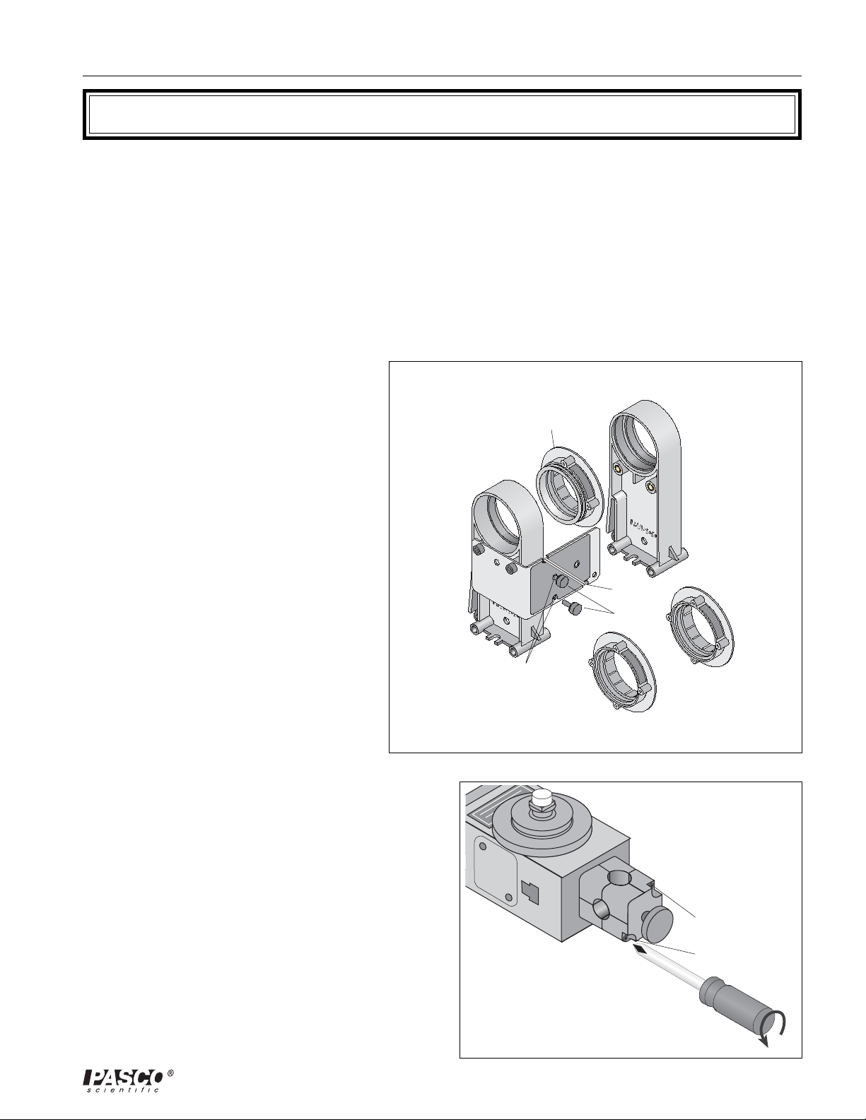
Mounting a Rotary Motion Sensor
Prepare the Rotary Motion Sensor
You will need a Phillips head screwdriver with a small tip
(e.g., #1).
The Rotary Motion Sensor comes with a rod clamp
Rotary Motion Sensor
rod clamp
Remove two
screws from the
rod clamp.
Phillips head screwriver
Figure 2: Remove Rod Clamp
1
Page 5
Polarization Analyzer 012-09200A
attached to one end. Use a Phillips head screwdriver to loosen the two
screws that hold the rod clamp. Remove the rod clamp and screws.
(Please put the rod clamp and screws in a safe place for future use.)
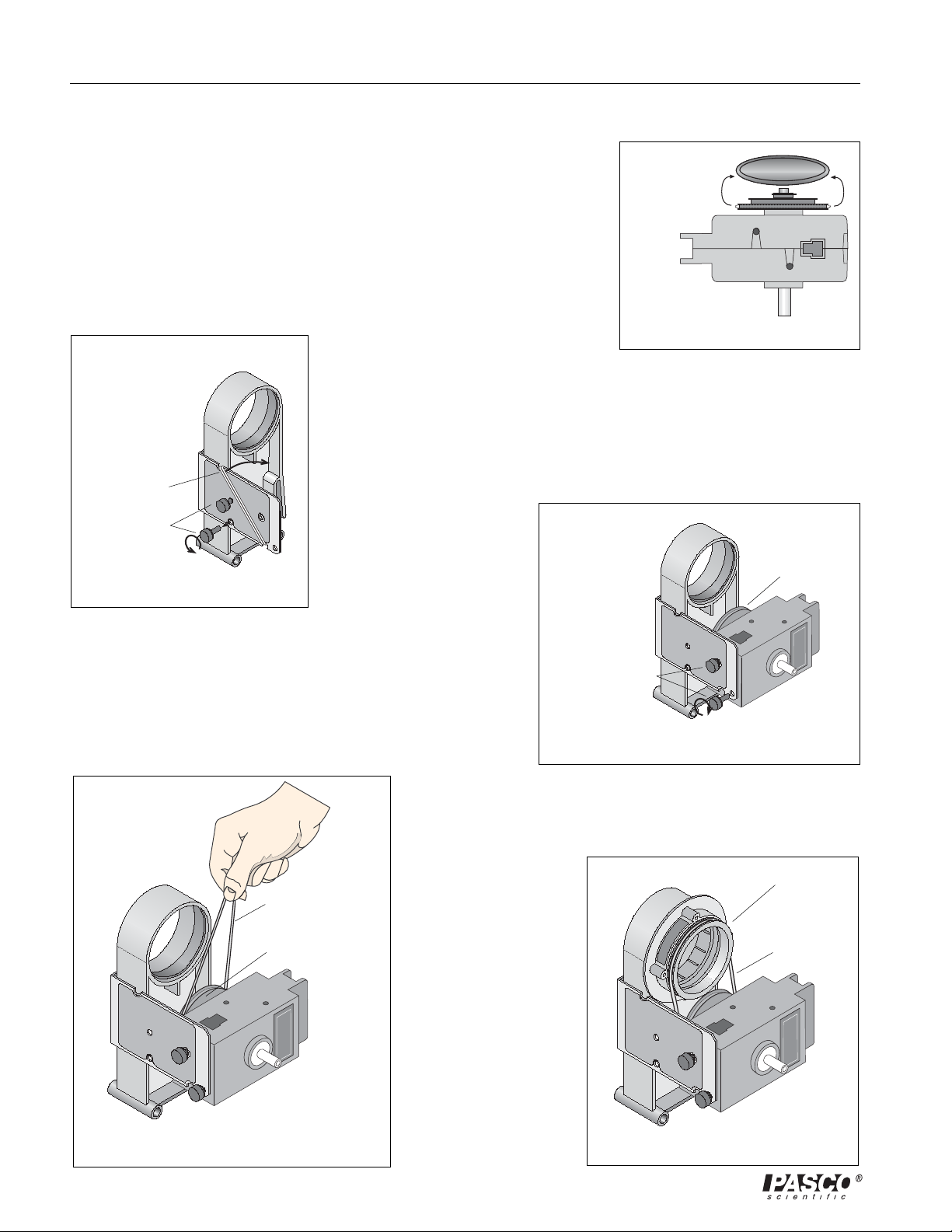
“O” ring
The Rotary Motion Sensor also comes with a rubber “O” ring in the
largest groove of the three-step pulley that is attached to the sensor’s
shaft. Remove the “O” ring from the three-step pulley and put the ring
in a safe place for future use. The sensor is now ready to mount on the
Accessory Holder bracket.
Prepare the Mounting Bracket
The bracket comes with two thumbscrews stored in threaded holes on
the side of the bracket. Remove the
Accessory Holder
two thumbscrews and set them aside for now.
The bracket also holds the plastic belt. The belt is wrapped twice around
Mounting Bracket
two semi-circular notches on the top and bottom edges of the bracket.
Unwrap the belt from the notches and set it aside for now.
plastic belt
thumbscrews
Attach the Rotary
Motion Sensor
Turn the Rotary Motion
Accessory Holder
Mounting Bracket
Figure 4: Prepare Bracket
Sensor so the three-step
pulley faces the Accessory
Holder and the threaded
holes in the end of the
sensor line up with the holes of the Mounting Bracket. Use
the two thumbscrews to attach the Rotary Motion Sensor to
the Mounting Bracket.
three-step pulley
Rotary Motion Sensor
Figure 3: Remove “O” Ring
three-step pulley
thumbscrews
Put on the Plastic Belt
Loop the bottom of the plastic belt around the three-step
pulley of the
Rotary Motion
Sensor so the bottom
of the belt is in the
large-diameter
groove of the step-
plastic belt
pulley.
Attach the Polarizer
three-step pulley
Get the Polarizer that
has the groove on its
front edge. Slip the
top of the plastic belt
into the groove on
the front edge of the
Polarizer. Snap the
Polarizer into place
Rotary Motion Sensor
Figure 6: Put on Plastic Belt
on the Accessory
Holder.
Rotary Motion Sensor
Figure 5: Attach Sensor to Bracket
Polarizer with Groove
plastic belt
Figure 7: Attach Polarizer
2
Page 6

012-09200A Polarization Analyzer
Using the Rotary Motion Sensor
Mount the Accessory Holder on the Optics Bench
The Accessory Holder snaps into the Optics Bench. To move the
Accessory Holder along the bench, grasp the base of the holder
and squeeze the locking clip inward. Continue to squeeze inward
on the locking clip as you move the holder to a new position.
When you release the locking clip, the Accessory Holder is held
firmly in place.
Rotate the
Polarizer
Rotate the Polarizer
by grasping the edge
Polarizer
of the Polarizer. As
you turn the Polarizer, the plastic belt
will turn the threestep pulley on the
Rotary Motion
Sensor by the same amount. When the Rotary Motion Sensor
is connected to ScienceWorkshop or PASPORT interface, you
Rotary Motion
Sensor
can measure the angular position of the Polarizer to within
one-quarter degree.
Polarizer
Rotary Motion
Accessory
Holder
locking clip
Optics Bench
Figure 8: Holder on Bench
Sensor
position
indicator
Figure 9: Rotate the Polarizer
Aperature Bracket
The Aperture Bracket has two main components: the Light
locking clip
Aperture Bracket
Holder
Sensor Mount and the Aperture Bracket Holder.
Light Sensor Mount
The Light Sensor Mount has an Aperture Bracket Screen, an
Aperture Disk, a large thumbscrew, and a threaded post. You
can use either the large thumbscrew or the threaded post to
Optics Bench
attach a Light Sensor to the Light Sensor Mount in one of two
positions. Use the threaded post if you want to hold the Light
Sensor Mount in a rod clamp. The large thumbscrew or the
post is stored in the threaded storage hole on the Light Sensor
Mount when not in use.
Aperture Bracket Holder
position
indicator
Figure 10: Holder on Bench
Two metal thumbscrews attach the Aperture Bracket Holder to
the back of the Light Sensor Mount. The Aperture Bracket Holder snaps into place anywhere along the
center section of the Optics Bench that is part of the OS-8515 Basic Optics System. To move the holder
along the bench, grasp the base of the holder and squeeze the locking clip inward. Continue to squeeze
inward on the locking clip as you move the holder to the new position. When you release the locking clip,
the holder is held firmly in place.
3
Page 7

Polarization Analyzer 012-09200A
Aperture Bracket Screen
The Aperture Bracket Screen is designed to help you align the Aperture Disk with a light source. Two
small thumbscrews attach the Aperture Bracket Screen to the front of the Light Sensor Mount.
Aperture Disk
The Aperture Disk has three circular apertures and six slit apertures (numbered one through six). The slit
widths are as follows:
1 = 0.1 mm 2 = 0.2 mm
3 = 0.3 mm 4 = 0.5 mm
5 = 1.0 mm 6 = 1.5 mm
One circular aperture is 8 mm in diameter, the
Aperture Disk
same dimension as the opening of the PASCO
Model CI-6504A, CI-6604, or PS-2106 Light
Sensor. A second circular aperture has the same
diameter but has a grid pattern of small holes (0.25
mm diameter) that allows 10% transmission of light
through the aperture. The third circular aperture is
2 mm in diameter, or one-fourth the diameter of the
larger circular apertures, and translucent.
slit apertures
(1 - 6)
Aperture Bracket
Screen
5
6
4
3
10%
2
1
circular
apertures
The Aperture Disk can be rotated to any of the nine
positions to put one of the slits or circular apertures
Figure 11: Aperture Disk
in line with a Light Sensor mounted behind the
Aperture Disk.
Using the Aperature Bracket
Mounting a Light Sensor
Aperture
Aperture Bracket
Holder
Light Sensor
Light Sensor Mount
Light Sensor
You can use the Aperture Bracket to
mount a Light Sensor on the Optics
Bench. You can use the Light Sensor to
measure the intensity of light through the
Polarizers as you rotate one Polarizer
relative to the other.
Use either the large thumbscrew or the
post to mount a Light Sensor to the Light
Aperture Disk
Light Sensor
large thumbscrew
into front hole
Sensor Mount. Position the Light Sensor
on top of the Light Sensor Mount so the
hole in the bottom of the sensor is in line
with the front hole in the mount and the
opening of the Light Sensor touches the
Figure 12: Mount the
Light Sensor
Figure 13: Light Sensor
onto Mount
vertical part of the Light Sensor Mount.
Put the threaded end of the thumbscrew or post through the hole and turn the thumbscrew or post clockwise to tighten. See Figure 12 & 13.
Snap the Aperture Bracket Holder into the Optics Bench.Rotate the Aperture Disk so the open circular
aperture is in line with the opening to the Light Sensor.
4
Page 8

012-09200A Polarization Analyzer
Setup for Measuring Light Intensity
You can use the Basic Optics Bench, Basic Optics Light Source,
Polarization Analyzer, Rotary Motion Sensor, Aperture Bracket,
Polarizer Mount
and a Light Sensor to measure the light intensity through the
Polarizers as one Polarizer is rotated relative to the other.
Prepare the Polarizer
Put the second Polarizer in the empty Polarizer Mount that comes
with the Polarization Analyzer.
Mount the Light Source
Put the Basic Optics Light Source at one end of the Basic Optics
Bench. Refer to the OS-8515 instructions. Turn the Light Source
so it produces a “point source” of light that is aimed toward the
other end of the bench.
Mount the Polarization Analyzer
Snap the Polarizer Mount onto the Optics Bench. Snap the Polarization Analyzer with Rotary Motion
Sensor onto the Optics Bench.
Mount the Light Sensor
Basic Optics Light Source
Polarizer Holder
Snap the Aperture Bracket Holder
with the Light Sensor onto the Optics
Bench with the Light Sensor opening
toward the Light Source
POLARIZER MOUNT
Polarizer
Figure 14: Prepare Polarizer
Light Sensor
Aperture Bracket
Holder
Polarization Analyzer with
Rotary Motion Sensor
Figure 15: Setup for Measuring Light Intensity
5
Optics Bench
Page 9

Polarization Analyzer 012-09200A
Notes:
6
Page 10

E=E
φ
I=I
0
φ
012-09200A Polarization Analyzer
V erify Malus’ Law of Polarization
EQUIPMENT NEEDED
– Basic Optics Bench (part of OS-8515) – Light Sensor (CI-6504A or PS-2106)
– Basic Optics Light Source (part of OS-8515) – Rotary Motion Sensor (CI-6538 or PS-2120)
– Polarization Analyzer with Aperture Bracket (OS-8533A)
Introduction
The purpose of this laboratory activity is to determine the relationship between the intensity of the transmitted
light through two polarizers and the angle, Ø, of the axes of the two polarizers.
Theory
A polarizer only allows light which is vibrating
Polarizer 2
0
cos
in a particular plane to pass through it. This plane
Polarizer 1
forms the “axis” of polarization. Unpolarized
light vibrates in all planes perpendicular to the
direction of propagation. If unpolarized light is
incident upon an “ideal” polarizer, only half will
be transmitted through the polarizer. Since in
reality no polarizer is “ideal”, less than half the
2
light will be transmitted.
unpolarized light
polarized light, I
The transmitted light is polarized in one plane. If
this polarized light is incident upon a second
polarizer, the axis of which is oriented such that
it is perpendicular to the plane of polarization of
the incident light, no light will be transmitted
through the second polarizer.
However, if the second polarizer is oriented at an
angle so that it is not perpendicular to the first
polarizer, there will be some component of the
component of polarized light parallel to
axis of Polarizer 2
Figure 1.1: Polarization
electric field of the polarized light that lies in the
same direction as the axis of the second polarizer,
thus some light will be transmitted through the second polarizer (see the bottom figure).
φ
I = I0cos2 φ
The component, E, of the polarized electric field, E
, is found by:
o
cos
0
Since the intensity of the light varies as the square of the electric field, the light intensity transmitted through
the second filter is given by:
where Io is the intensity of the light passing through the first filter and Ø is the angle between the polarization
axes of the two filters.
7
Page 11

Polarization Analyzer 012-09200A
PASCO
scientific
Consider the two extreme cases illustrated by this equation:
2
• If Ø is zero, the second polarizer is aligned with the first polarizer, and the value of cos
Ø is one. Thus the
intensity transmitted by the second filter is equal to the light intensity that passes through the first filter. This
case will allow maximum intensity to pass through.
• If Ø is 90º, the second polarizer is oriented perpendicular to the plane of polarization of the first filter, and the
2
(90º) gives zero. Thus no light is transmitted through the second filter. This case will allow minimum inten-
cos
sity to pass through.
• These results assume that the only absorption of light is due to polarizer effects. In fact most polarizing films
are not clear and thus there is also some absorption of light due to the coloring of the Polaroid filters.
Procedure
In this activity, the Light Sensor measures the relative intensity of light that passes through two polarizers. You
will change the angle of the second polarizer relative to the first. The Rotary Motion Sensor measures the
angle.
The DataStudio records and displays the light intensity and the angle between the axes of the polarizers. You
can use the program’s built-in calculator to compare the relative intensity to the angle, the cosine of the angle,
and the cosine
2
of the angle.
Equipment Setup
1. Mount the Basic Optics
Light Source, Polarizer
Holder, Polarizer Analyzer
with Rotary Motion Sensor,
and Aperture Bracket
Holder with Light Sensor as
shown. (Refer to the Introduction for more information.)
2. Connect the Light Sensor
and Rotary Motion Sensor
to the computer through a
ScienceWorkshop or
PASport interface (or interfaces), and start DataStudio.
Light Sensor
Aperture Disk
Polarizers
Rotary Motion
Sensor
Light Source
Optics Bench
Figure 2: Equipment Setup
8
Page 12

012-09200A Polarization Analyzer
Experiment Setup
Select the Sensors and Set the Sample Rate
• Refer to DataStudio on-line help for detailed information on selecting sensors and changing the sample rate.
1. Set up the Rotary Motion Sensor for high resolution (for example, 1440 Divisions per Rotation). Select Large
Pulley (Groove) for the linear calibration (if you are using a PASport Sensor, this step is unecessary).
2. Set the sample rate of both sensors to 20 Hz, or 20 measurements per second.
Select the Display
• Refer to DataStudio on-line help for detailed information selecting and changing displays.
1. Select a Graph display.
2. Set the axes of the Graph display so light intensity is on the vertical axis and angular position is on the horizon-
tal axis.
Prepare to Record Data
• Refer to DataStudio on-line help for detailed information on monitoring and recording data.
1. Turn both Polarizers so they are at the same beginning angle (e.g., zero degrees).
2. Start monitoring data.
3. Rotate one Polarizer back and forth until the transmitted light intensity is maximum.
4. Stop monitoring data.
Record Data
1. Start recording data.
2. Slowly rotate the Polarizer on the Polarization Analyzer in the clockwise direction. Continue to rotate the Polarizer until you have made one complete rotation (360 degrees).
3. After one complete rotation, stop recording data.
Analyze the Data
• Refer to the on-line help for DataStudio detailed information on creating and displaying calculations and using
DataStudio for data analysis.
1. Use the Experiment Calculator in DataStudio software to create a calculation of the cosine of the angle between
the Polarizers.
2
2. Repeat the procedure to create a calculation of the cosine
3. Use the Graph display to examine the plot of light intensity versus angle.
of the angle of the Polarizers.
4. Change the Graph display to show the plot of light intensity versus the cosine of the angle, and then change the
2
Graph display to show the plot of light intensity versus the cosine
5. Use Data Studio software to determine the relationship between the light intensity and the cosine
9
of the angle.
2
of the angle.
Page 13

Polarization Analyzer 012-09200A
Questions
1. What is the shape of the plot of light intensity versus angle?
2. What is the shape of the plot of light intensity versus cosine of the angle?
3. What is the shape of the plot of light intensity versus cosine
2
of the angle?
4. Theoretically, what percentage of incident plane polarized light would be transmitted through three Polarizers
which have their axes rotated 17 degrees (0.29 radians) from each other?Assume ideal polarizers and assume
that the second polarizer’s axis is rotated 17 degrees (0.29 radians) from the first and that the third polarizer’s
axis is rotated 17 degrees (0.29 radians) from the second.
5. From your data, determine the answer to Question #4 for the real polarizers.
10
Page 14

012-09200A Polarization Analyzer
Teacher’s Guide
Data Analysis
Sample Data
In the data analysis section, the curve fit for the polynomial function is
second degree. This indicates that the light
intensity varies as the square of the cosine of φ. This is confirmed by the curve fit for the linear function when
light intensity is compared to the square of the cosine.
Answers to Questions
1. What is the shape of the graph of the intensity versus the
angle?
Answers will vary. The shape of the graph of the intensity
vs. the angle is approximately sinusoidal.
2. What is the shape of the graph of the intensity versus the
cosine of the angle?
The shape of the graph of the intensity vs. the cosine of the
angle is a parabola.
Sample Data: Light Intensity versus Angle
3. What is the shape of the graph of the intensity versus the
square of the cosine of the angle?
The shape of the graph of the intensity vs. the square of
the cosine of the angle is a straight line.
4. Theoretically, what percentage of incident plane polarized
light would be transmitted through three polarizers which
each have their axes rotated 17 degrees from each other?
Assume ideal polarizers and assume that the first
polarizer’s axis is 17 degrees from the axis of the second
polarizer.
Assuming ideal filters, the intensity passing through the
first filter would be 50% of the initial intensity. The
intensity after the second filter would be reduced by
2
(17½) = 0.9145 of the intensity passing through the
cos
first filter. Thus the intensity after passing through two
filters would be 45.73%. The light passing through the
third filter would be reduced by another 0.9145. So the
three polarizers reduces the light intensity to
50%*(0.9145)2 = 41.82%.
5. From your graph, determine the answer to Question #4
for the real polarizers.
Answers will vary. From the example, we see that the
intensity at 17½ is 98%, so the final intensity should be
2
= 96% of the intensity that passes through the first
(.98)
filter. Using the sample data we see that only 33% passes
through the first filter, thus the intensity of the light that
passes through three filters is 96% of 33% or 31.68%.
11
Sample Data: Light Intensity vs. Cosine Angle
Sample Data: Light Intensity vs. Cosine2 Angle
Page 15

Polarization Analyzer 012-09200A
Notes:
Page 16

Technical Suppor t
Feedback
If you have any comments about the product or manual,
please let us know. If you have any suggestions on
alternate experiments or find a problem in the manual,
please tell us. PASCO appreciates any customer
feedback. Your input helps us evaluate and improve our
product.
To Reach PASCO
For technical support, call us at 1-800-772-8700 (tollfree within the U.S.) or (916) 786-3800.
fax: (916) 786-3292
e-mail: techsupp@pasco.com
web: www.pasco.com
Contacting Technical Support
Before you call the PASCO Technical Support staff, it
would be helpful to prepare the following information:
➤ If your problem is with the PASCO apparatus, note:
- Title and model number (usually listed on the
label);
- Approximate age of apparatus;
- A detailed description of the problem/sequence of
events (in case you can’t call PASCO right away,
you won’t lose valuable data);
- If possible, have the apparatus within reach when
calling to facilitate description of individual parts.
➤ If your problem relates to the instruction manual,
note:
- Part number and revision (listed by month and
year on the front cover);
- Have the manual at hand to discuss your
questions.
 Loading...