

Page 1
Instruction Sheet
for the PASCO
Model OS-8520
012-05631A
3/95
$1.00
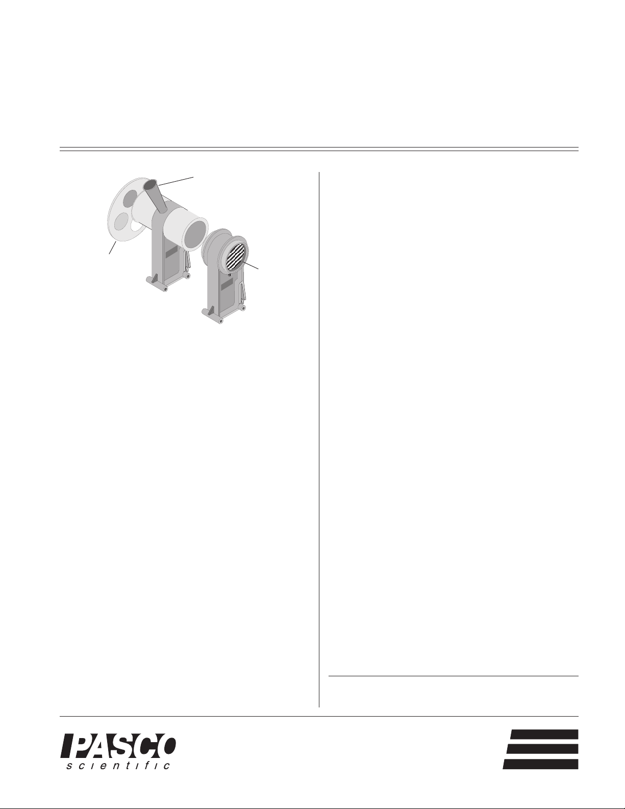
PHOTOMETER
Eyepiece
Neutral Density
Filter
Polarizer
Introduction
The PASCO OS-8520 Photometer is a non-electric comparative instrument which was designed as an accessory
for the OS-8515 Basic Optics System. The Photometer
base can stand on any flat surface for use with other optics
systems or for experiments not requiring an optics bench.
Equipment
The OS-8520 Photometer includes:
–Photometer with Base
– Set of Polarizers and Accessory Holder
– Neutral Density Filter Set which allows 25%,
50%, 75% and 100% transmittance.
Photometer
The PASCO OS-8520 Photometer operates in a similar
fashion to a wax photometer except the wax is replaced
by two high brightness fluorescent acrylic disks. By looking through the eyepiece, students can see if the disks,
each receiving light from an opposite side of the photometer, are equal in intensity. Although it is difficult for the
eye to determine relative intensities, it can detect equal
intensities quite accurately.
A set of neutral density transmission filters (25, 50, 75,
and 100%) are included to be used on the Photometer to
block out a known amount of light so quantitative measurements may be made. Note that because the Photometer uses a fluorescent material, it will not respond
equally in the red and violet parts of the spectrum. This
Photometer was designed to be used with white light,
such as the PASCO Light Source (OS-8517). To decrease the intensity of the light that is emitted by the light
source, use a mask rather than decreasing the voltage to
the bulb. The use of a mask preserves the white color of
the light whereas a decrease in the voltage would change
the color of the emitted light to red.
A set of two mounted polarizers is also included. The
polarizer perimeters are marked in degrees and the
polarizers can be rotated to any angle to show the amount
of extinction of the transmitted light.
All the filters snap into the ends of the photometer and
can be rotated once they are snapped into place. The
polarizers are designed to fit on their own separate holder.
One polarizer can be snapped into each side of the holder.
How to Use the Photometer
To determine if the two sides of the photometer are illuminated by light of equal intensity, look down into the
conical eyepiece of the photometer. The cone is designed
to cast a shadow on the inner parts of the photometer to
allow a better view. Do not put your eye directly on the
eyepiece: keep your head at a distance which allows you
to comfortably focus on the orange indicator. If the light
is the same brightness on each side, the color and brightness of the two sides of the orange indicator will appear to
be the same.
© 1995 PASCO scientific
This instruction sheet written/edited by: Jon Hanks
10101 Foothills Blvd. • P.O. Box 619011 • Roseville, CA 95678-9011 USA
Phone (916) 786-3800 • FAX (916) 786-8905 • email: techsupp@PASCO.com
better
ways to
teach physics
Page 2
Photometer 012-05631A
Limited Warranty
PASCO scientific warrants this product to be free from defects in materials and workmanship for a period of one
year from the date of shipment to the customer. PASCO
will repair or replace, at its option, any part of the product
which is deemed to be defective in material or workmanship. This warranty does not cover damage to the product
caused by abuse or improper use. Determination of
Experiment 1: Inverse Square Law
EQUIPMENT NEEDED
– Bench (OS-8518) – 2 Point light sources (OS-8517)
– Photometer with filter set (OS-8520)
Purpose
The purpose of this experiment is to show that light intensity is inversely proportional to the
square of the distance from a point light source.
Theory
whether a product failure is the result of a manufacturing
defect or improper use by the customer shall be made solely
by PASCO scientific. Responsibility for the return of equipment for warranty repair belongs to the customer. Equipment
must be properly packed to prevent damage and shipped
postage or freight prepaid. (Damage caused by improper
packing of the equipment for return shipment will not be covered by the warranty.) Shipping costs for returning the equipment, after repair, will be paid by PASCO scientific.
The light from a point light source spreads out uniformly in all directions. The intensity at a
given distance, r, from the light will be equal to the power output of the light divided by the
surface area of the sphere through which the light has spread. Since the area of the sphere goes
as the square of its radius, r, the intensity will drop off as 1/r2. In general, the intensity of the
point light source at any distance, r, is given by
Thus, the ratio of the intensity (I) of the light at a position (r) as compared to the reference intensity
(Io) measured at a position (ro) is given by
2
r
I
o
=
2
I
r
o
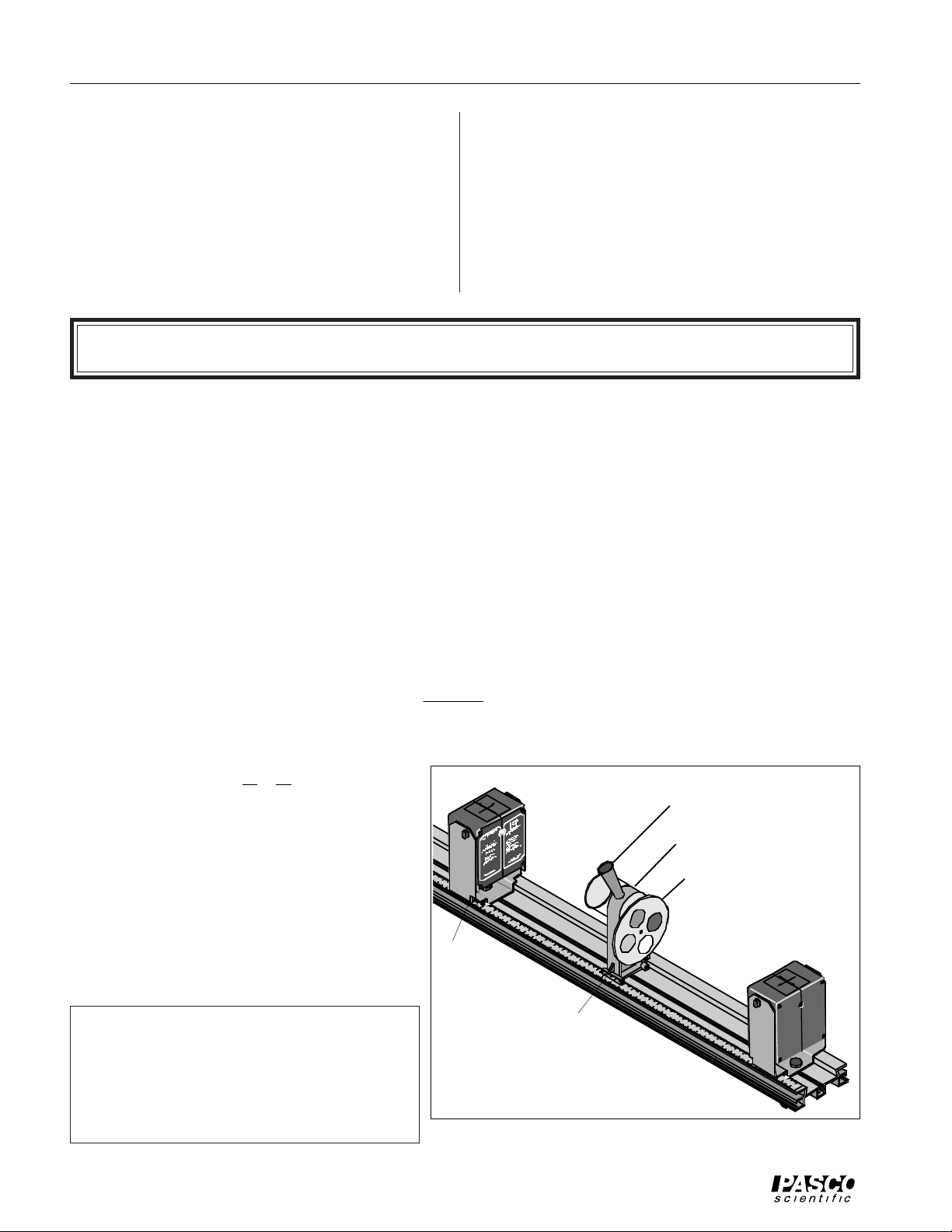
Set Up
➀ Place the photometer at the 70 cm mark on
the optics bench.
➁ Place a point light source at 40 cm. Put a
neutral density filter on the side of the
photometer that is opposite the point
source. See Figure 1.1. Place the other
light source on the same side of the bench
that has the neutral density filter.
➤ NOTE: This experiment can be done using
one point light source and a second light
source (used as a reference) that is not a point
source. If you are using only one point
source, put the point source on the side of the
photometer that does not have the filter.
➂ Adjust the neutral density filter for 100% transmittance.
I =
constant
2
r
Point Source
40 cm
70 cm
The bench and light source shown with the
Photometer are available as part of the
PASCO OS-8515, Basic Optics System
Figure 1.1: Experiment Set-Up
Eyepiece
Photometer
Filter
Second Light
Source
2
Page 3

012-05631A Photometer
Procedure
➤NOTE: You may want to cover the crossed-arrow object on each light source to reduce the
excess light in the room. The room lights must be off for this experiment.
➀ Turn off the room lights. The only sources of light should be the two point sources.
➂ Look into the photometer and move the light source on the filter side to a position that gives equal
intensities. The light source on the filter side will remain at this position for the rest of the experiment. This light will act as the reference intensity I
. Record the positions of the photometer and
o
the light source that is opposite the filter side of the photometer in Table 1.1. The position of the
reference light (on the filter side) is not needed.
➂ Rotate the neutral density filter to 75% transmittance. Move the point light source (the one oppo-
site the filter side) to the position where the intensities are once again the same when viewed in the
photometer. Record this new position of the light source in Table 1.1.
➃ Repeat the last step for 50% and 25% transmittance.
Analysis
Table 1.1: Positions
Photometer
Light Sources Intensity
Position
= _________
100% 75% 50% 25%
Position 1
Position 2
Position 3
Average Position
of Point Source
Distance
from Photometer
Calculated
Intensity
%
diff
➀ Using the measured positions in Table 1.1, calculate the distances of the point source from the
photometer and record in Table 1.1.
➁ For each of the different positions, calculate the intensity using
I =
I
o
r
2
r
o
where ro is the initial distance of the point source (100%) and r is the distance at the given intensity. Note that the intensity is calculated in terms of the initial intensity Io. Record your answers
in Table 1.1.
➂ Calculate the percent difference between the calculated intensities and their corresponding ex-
pected values. Record in Table 1.1.
3
Page 4

Photometer 012-05631A
Experiment 2: Polarization
EQUIPMENT NEEDED
– Optics bench (OS-8518) – 2 Point light sources (OS-8517)
– Photometer with filter set (OS-8520) – 2 Polarizers (OS-8520)
Purpose
The purpose of this experiment is to show that the intensity of the light transmitted through two
polarizers depends on the square of the cosine of the angle between the axes of the two
polarizers.
Theory
A polarizer only allows light which is vibrating in a particular plane to pass through it. This
plane forms the “axis” of polarization. Unpolarized light vibrates in all planes. Thus if unpolarized light is incident upon an “ideal” polarizer, only half will be transmitted through the
polarizer. (Since in reality no polarizer is “ideal”, less than half the light will be transmitted.)
The transmitted light is polarized in one plane. If this polarized light is incident upon a second
polarizer, the axis of which is oriented such that it is perpendicular to the plane of polarization
of the incident light, no light will be transmitted through the second polarizer (Figure 2.1).
Unpolarized
Light
First Polarizer
Polarized
Light
No Light
Second Polarizer
Figure 2.1: Unpolarized light incident on two polarizers
oriented perpendicularly to each other.
However, if the second polarizer is oriented at an angle so that it is not perpendicular to the first
polarizer, there will be some component of the electric field of the polarized light that lies in the
same direction as the axis of the second polarizer, and thus some light will be transmitted
through the second polarizer (Figure 2.2).
Unpolarized
Light
Polarized
Light
φ
I
o
φ
Polarized
Light
I = Io cos2φ
First Polarizer
Second Polarizer
Figure 2.2: Unpolarized light incident on two polarizers
oriented at an angle φ with respect to each other.
4
Page 5

012-05631A Photometer
The component, E, of the polarized electric field, Eo, is found by using trigonometry: E = Eo cosφ.
Since the intensity of the light goes as the square of the electric field, the transmitted light intensity is given by I = Io cos2φ, where Io is the incident light intensity and φ is the angle between the
axis of polarization of the incident light and the polarizer.
Notice that the two extremes work in this formula:
➀ If φ is zero, cos
2
(φ) equals one, and thus the intensity transmitted is equal to the incident inten-
sity of the polarized light because the polarizer is aligned with the incident light and will allow
all of it to pass through.
➤ NOTE: It is assumed that the incident light is polarized, not unpolarized.
➁ If φ is 90°, cos
2
(φ) equals zero, and no light is transmitted since the polarizer is oriented perpen-
dicular to the plane of polarization of the incident light.
Set Up
➀ Place the photometer in the middle of the optics
bench. Place the neutral density filter on one
side of the photometer. See Figure 2.3.
➁ Place a point light source on each end of the
optics bench.
➂ Snap one polarizer onto each side of the acces-
sory holder. Before beginning the experiment,
check the angle calibration on the polarizers in
the following way: On the side of the accessory holder that has the label, set the angle to
90 degrees. Look through both polarizers at a
bright light and rotate the other polarizer until
the transmitted light is at the minimum. Now
the polarizers are crossed at 90 degrees. Rotate
the label- side polarizer back to zero degrees.
Now the two polarizers are aligned for maximum transmission. Throughout the experiment, only rotate the label-side polarizer.
Point Source
Polarizer
Point Source
Polarizer
Indicator
The bench and light source shown with the
Photometer are available as part of the
PASCO OS-8515, Basic Optics System
Figure 2.3: Experiment Set-Up
➃ Place the polarizer accessory holder (with polarizers) on the bench between the light source and
the photometer on the side opposite the neutral density filter. The label side of the polarizer
holder should face away from the photometer. The polarizer holder should be close to the photometer so only polarized light will enter that side of the photometer.
5
Page 6

Photometer 012-05631A
Procedure
➤ NOTE: You may want to cover the crossed-arrow objects on each light source to reduce
the excess light in the room. The room lights must be off for this experiment.
➀ Set the neutral density filter for 100% transmission.
➁ While looking into the photometer’s conical eyepiece, adjust the position(s) of the light
source(s) until the two sides of the orange indicator have equal intensity.
➂ Set the neutral density filter for 75% transmission.
➃ While looking into the photometer’s conical eyepiece, rotate the label-side polarizer until the
two sides once again have equal intensity. Record the angle in Table 2.1. Rotate the polarizer
back to zero and repeat the measurement two more times.
➄ Repeat the previous step for 50% and 25% transmission.
Table 2.1: Data and Results
% transmittance 75% 50% 25%
trial 1
trial 2
trial 3
Average angle φ
cos2φ
% difference
Analysis
➀ For each of the neutral density filter settings, calculate the average of the three trials and
record the average angle in Table 2.1.
➁ To calculate the predicted percentage transmittance for each case, calculate the square of the
cosine of each average angle and record in Table 2.1.
➂ Calculate the percent difference between the percentage transmittance and the predicted value
for each case and record in Table 2.1.
6
 Loading...