

Page 1
Instruction Manual and
Experiment Guide for
the PASCO scientific
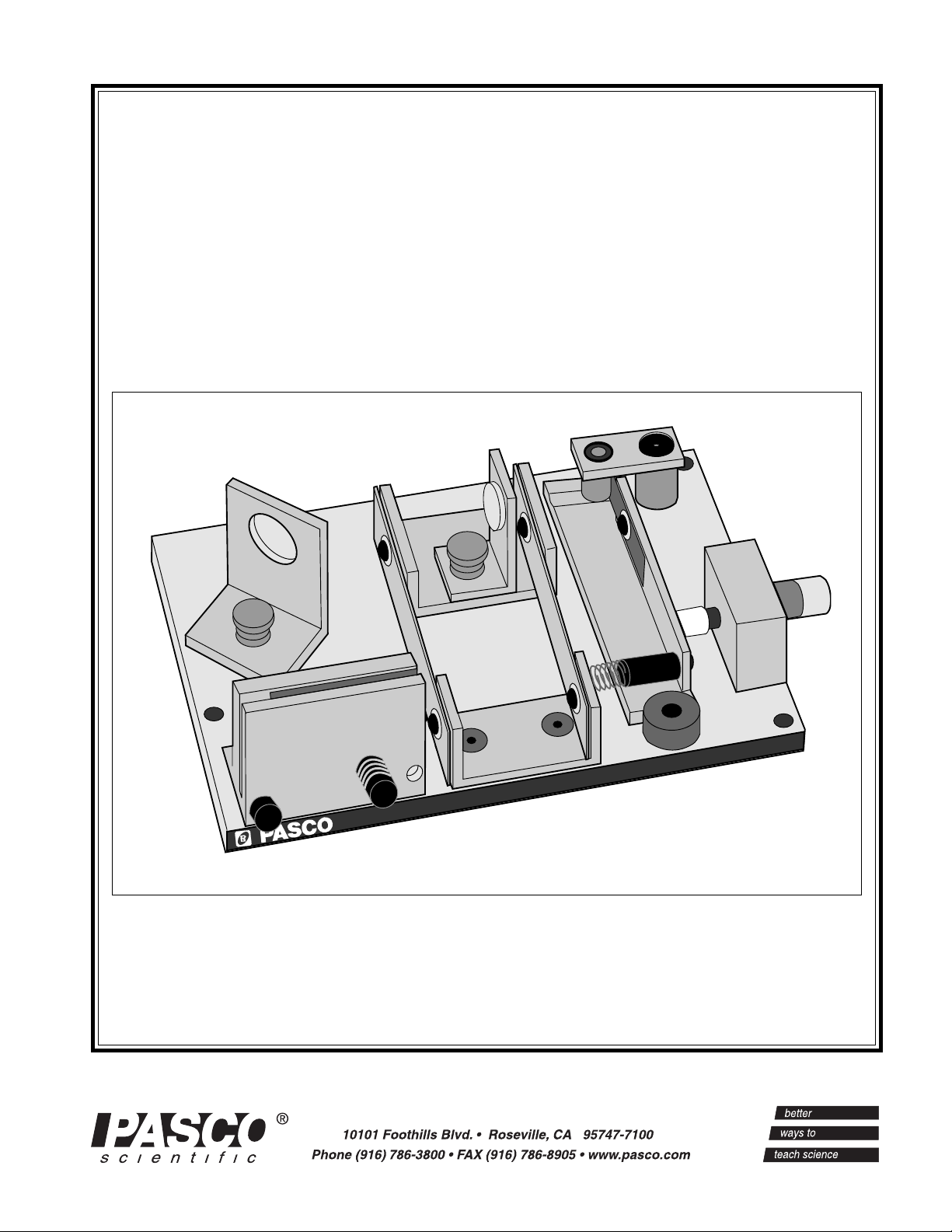
Model OS-8501
Interferometer
012-02675
10/91
Revision B
MODEL OS-8501 INTERFEROMETER
scientific
Copyright © February 1986 $10.00
Page 2

Page 3

Interferometer 012-02675B
Table of Contents
Section Page
Copyright, Warranty, and Equipment Return........................................ ii
Introduction...............................................................................................1
Equipment .................................................................................................1
Equipment included:
Additional Equipment Needed:
Additional Equipment Recommended:
Theory of Operation .................................................................................2
Interference Theory
The Michelson Interferometer
Operation
The Interferometer.........................................................................................4
The Movable Mirror .......................................................................................4
Aligning the Interferometer ..........................................................................5
Exp 1: Measuring the Wavelength of Light .......................................... 7
Exp 2: Measuring the Index of Refraction for Air ................................ 8
Appendix
Maintenance.................................................................................................11
Replacement Parts ......................................................................................11
Inteferometry with a Spectral Light Source ..............................................12
i
scientific
Page 4
012-02675B Interferometer
Copyright, Warranty and Equipment Return
Please—Feel free to duplicate this manual
subject to the copyright restrictions below.
Equipment Return
Copyright Notice
The PASCO scientific Model OS-8501 Interferometer
manual is copyrighted and all rights reserved. However, permission is granted to non-profit educational
institutions for reproduction of any part of this manual
providing the reproductions are used only for their
laboratories and are not sold for profit. Reproduction
under any other circumstances, without the written
consent of PASCO scientific, is prohibited.
Should the product have to be returned to PASCO
scientific for any reason, notify PASCO scientific by
letter, phone, or fax BEFORE returning the product.
Upon notification, the return authorization and
shipping instructions will be promptly issued.
ä
NOTE: NO EQUIPMENT WILL BE
ACCEPTED FOR RETURN WITHOUT AN
AUTHORIZATION FROM PASCO.
Limited Warranty
PASCO scientific warrants this product to be free from
defects in materials and workmanship for a period of
one year from the date of shipment to the customer.
PASCO will repair or replace, at its option, any part of
the product which is deemed to be defective in material or workmanship. This warranty does not cover
damage to the product caused by abuse or improper
use. Determination of whether a product failure is the
result of a manufacturing defect or improper use by the
customer shall be made solely by PASCO scientific.
Responsibility for the return of equipment for warranty
repair belongs to the customer. Equipment must be
properly packed to prevent damage and shipped
postage or freight prepaid. (Damage caused by
improper packing of the equipment for return shipment
will not be covered by the warranty.) Shipping costs
for returning the equipment, after repair, will be paid
by PASCO scientific.
When returning equipment for repair, the units
must be packed properly. Carriers will not accept
responsibility for damage caused by improper
packing. To be certain the unit will not be
damaged in shipment, observe the following rules:
➀ The packing carton must be strong enough for the
item shipped.
➁ Make certain there are at least two inches of
packing material between any point on the
apparatus and the inside walls of the carton.
➂ Make certain that the packing material cannot shift
in the box or become compressed, allowing the
instrument come in contact with the packing
carton.
Address: PASCO scientific
10101 Foothills Blvd.
Roseville, CA 95747-7100
scientific
Phone: (916) 786-3800
FAX: (916) 786-3292
email: techsupp@pasco.com
web: www.pasco.com
ii
Page 5
012-02675B Interferometer
Introduction
The PASCO scientific Model OS-8501
Michelson Interferometer is a precision instrument capable of measuring the wavelength of
visible, monochromatic light with an
accuracy of better than 5%. With the
included vacuum chamber, it can also be
used for precise measurements of the index of
air refraction.
➧ CAUTION: Avoid touching all optical
surfaces on the interferometer, because
minute scratches can impair the clarity of
the interference image. For instructions
on cleaning the optical surfaces, see the
Maintenance section at the end of this
manual.
scientific
MODEL OS-8501 INTERFEROMETER
Equipment
Equipment included:
• Interferometer base with built-in micrometer
and leveling feet
• Movable mirror
• Beam splitter
• Three point adjustable fixed mirror
• Vacuum cell for measuring the index of
air refraction
• Beam expanding lens with component holder
• Fitted case
Additional Equipment Needed:
Light source: To operate the Michelson Interferom-
eter you will also need a monochromatic light source,
preferably a laser. We recommend the PASCO 0.5
mW He-Ne Laser (Model OS-9171), but any low
power laser that operates in the visible range will
work. For optimum ease of alignment, the level of the
beam should be 1.5 inches (3.8 cm) above the bench
top. Leveling screws on the interferometer allow the
height to be adjusted.
Vacuum pump: To measure the index of refraction of
air, you will also need a vacuum pump. The PASCO
Hand Vacuum Pump (Model OS-8502) is an accurate
yet relatively inexpensive pump with a built-in gauge.
It allows precise control of the vacuum level when
counting fringes. However, the vacuum chamber can
be used with any pump that can be connected by a 1/4
inch (0.64 cm) I.D. (inner diameter) tube.
➧ CAUTION: Do not use the vacuum chamber
with a compressor; it is not built to withstand
positive pressures.
Additional Equipment Recommended:
The PASCO Optics Bench can function as an aid in
aligning the interferometer. It simplifies the alignment
procedure and the magnetic pads on the bench top hold
the laser and interferometer firmly in position once the
system is aligned. A 1.0 m Optics Bench can be purchased separately (Model OS-9103). A 70 cm optics
bench is included as an integral part of the PASCO
scientific Introductory Optics System (Model OS-
8500).
scientific
1
Page 6
Interferometer 012-02675B
LASER
VIEWING SCREEN
M
2
M1 (FIXED MIRROR)
BEAM-
SPLITTER
(MOVABLE
MIRROR)
Theory of Operation
Interference Theory
A beam of light can be modeled as a wave of oscillating electric and magnetic fields. When two beams of
light meet in space, these fields add according to the
principle of superposition. At each point in space, the
electric and magnetic fields are determined as the
vector sum of the fields of the separate beams.
If the two beams of light originate from separate
sources, there is generally no fixed relationship
between the electromagnetic oscillations in the beams.
If two such light beams meet, at any instant in time
there will be points in space where the fields add to
produce a maximum field strength. However, the
oscillations of visible light are much faster than the
human eye can apprehend. Since there is no fixed
relationship between the oscillations, a point at which
there is a maximum at one instant may have a minimum at the next instant. The human eye averages
these results and perceives a uniform intensity of light.
However, if the two beams of light originate from the
same source, there is generally some degree of correlation between the frequency and phase of the oscillations of the two beams. At one point in space the light
from the beams may be continually in phase. In this
case, the combined field will always be a maximum
and a bright spot will be seen. At another point the
light from the two beams may be continually out of
phase and a minima, or dark spot, will be seen.
The Michelson Interferometer
In 1881, some 78 years after Young introduced his
two-slit experiment, A.A. Michelson designed and
built an interferometer using a similar principle.
Originally Michelson designed his interferometer as a
method to test for the existence of the ether, a hypothesized medium in which light could propagate. Due in
part to his efforts, the ether is no longer considered a
viable hypothesis. Michelson’s interferometer has
become a widely used instrument for measuring the
wavelength of light, and for using the wavelength of a
known light source to measure extremely small
distances.
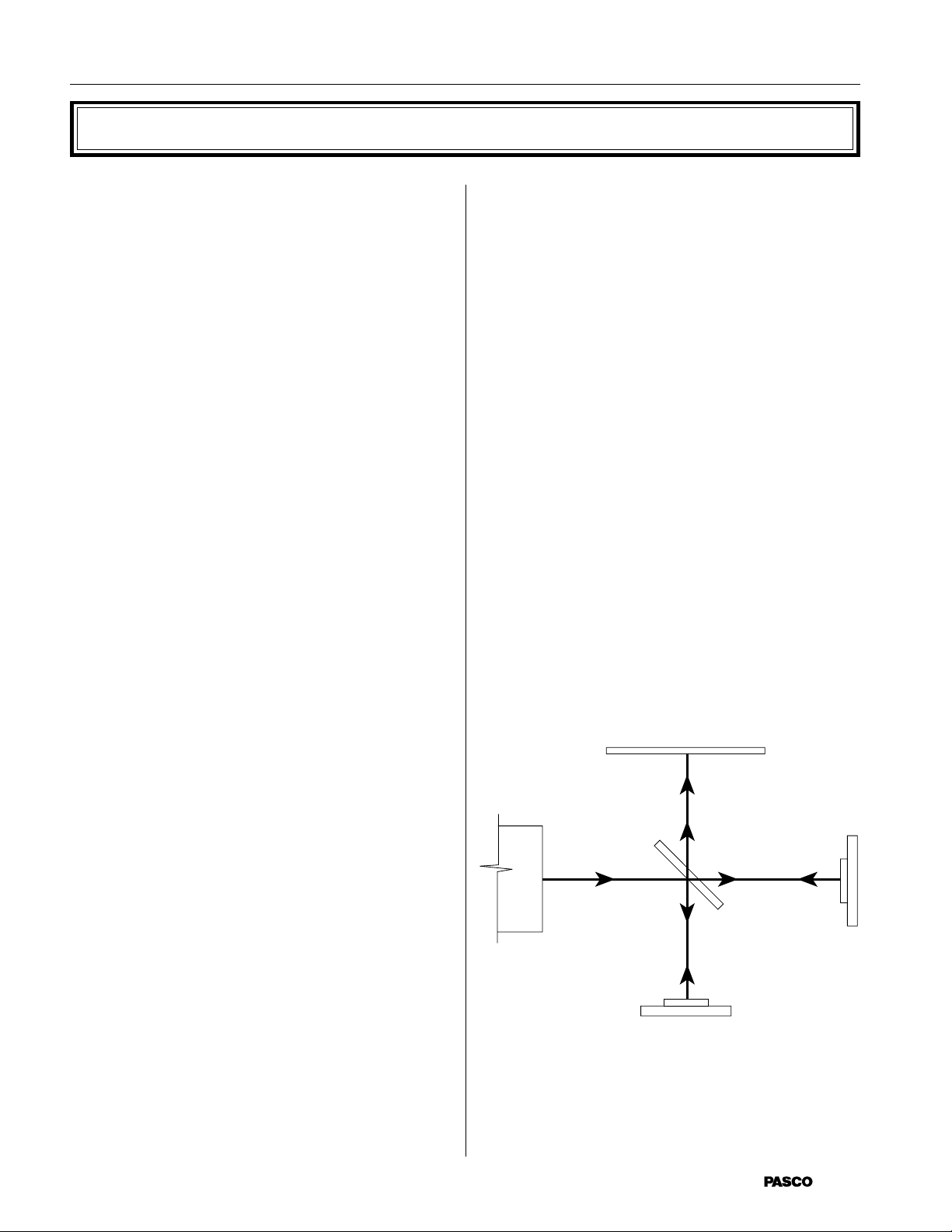
Figure 1 shows a diagram of a Michelson interferometer. A beam of light from the laser source strikes the
beam-splitter. The beam-splitter is designed to reflect
50% of the incident light and transmit the other 50%.
The incident beam therefore splits into two beams; one
beam is reflected toward mirror M
transmitted toward mirror M
beams back toward the beam-splitter. Half the light
from M1 is transmitted through the beam-splitter to the
viewing screen and half the light from M
by the beam-splitter to the viewing screen.
, the other is
1
. M1 and M2 reflect the
2
is reflected
2
Thomas Young was one of the first to design a method
for producing such an interference pattern. He allowed
a single, narrow beam of light to fall on two narrow,
closely spaced slits. Opposite the slits he placed a
viewing screen. Where the light from the two slits
struck the screen, a regular pattern of dark and bright
bands became visible. When first performed, Young’s
experiment offered important evidence for the wave
nature of light.
Young’s slits function as a simple interferometer. If
the spacing between the slits is known, the spacing of
the maxima and minima can be used to determine the
wavelength of the light. Conversely, if the wavelength
of the light is known, the spacing of the slits could be
determined from the interference patterns.
Figure 1 MICHELSON INTERFEROMETER
2
scientific
Page 7

012-02675B Interferometer
In this way the original beam of light splits, and
portions of the resulting beams are brought back
together. The beams are from the same source and
their phases highly correlate. When a lens is placed
between the laser source and the beam-splitter, the
light ray spreads out. An interference pattern of dark
Figure 2 INTERFERENCE PATTERN
and bright rings, or fringes, is seen on the viewing
screen, as shown in Figure 2.
➦ NOTE: Do not be concerned if your pattern
shows irregularities or has fewer fringes. As
long as fringes are clearly visible, measurements
will be accurate.
Since the two interfering beams of light were split
from the same initial beam, they were initially in
phase. Their relative phase when they meet at any
point on the viewing screen, therefore, depends on the
difference in the length of their optical paths in reaching that point.
By moving mirror M
, the path length of one of the
2
beams can be varied. Since the beam traverses the
path between M
M
1/4 wavelength nearer the beam-splitter will reduce
2
and the beam-splitter twice, moving
2
the optical path of that beam by 1/2 wavelength. The
interference pattern will change; the radii of the
maxima will be reduced so they now occupy the
position of the former minima. If M
is moved an
2
additional 1/4 wavelength closer to the beam-splitter,
the radii of the maxima will again be reduced so
maxima and minima trade positions. However, this
new arrangement will be indistinguishable from the
m
original pattern.
By slowly moving M
a measured distance dm, and
2
counting m, the number of times the fringe pattern is
restored to its original state, the wavelength of the light
(λ) can be calculated as:
2d
λ =
m
If the wavelength of the light is known, the same
procedure can be used to measure d
.
m
scientific
3
Page 8

Interferometer 012-02675B
Operation
The Interferometer
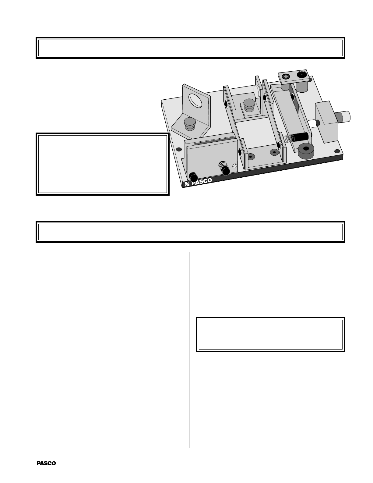
The Michelson Interferometer is shown in
Figure 3. The alignment of the beamsplitter and the movable mirror, M
2
, is
easily adjusted by loosening the thumbscrews that attach them to the interferometer. The fixed mirror, M
, is mounted on
1
an alignment bracket. The bracket has two
alignment screws to adjust the angle of the
mirror.
The movement of M
toward and away
2
from the beam-splitter is controlled and
measured using the micrometer knob.
Each division of the knob corresponds to 1
micrometer
(10-6 meter) of mirror movement.
BEAM SPLITTER
M1 (FIXED MIRROR)
The Movable Mirror
To measure the wavelength of light, the movement of
M
must be measurable for distances about 10
2
meters. Also, as the mirror moves, its reflective
surface must remain perpendicular to the axis of the
incident light beam.
A taut-band carriage is used to maintain the alignment
of the reflective surface of M
as it moves. The mirror
2
is mounted in a cradle that is fixed to two semi-rigid
aluminum bands. With this set-up the mirror is free to
move, but its movement is constrained to a line
parallel with the beam axis.
The micrometer mechanism controls and measures the
movement of M
. The cradle of M2 is attached to a
2
mylar strip that is attached to a lever arm. The displacement of the lever is controlled with the micrometer knob.
-6
M2 (MOVABLE MIRROR)
M1 ALIGNMENT
SCREWS
MICROMETER
KNOB
Figure 3 INTERFEROMETER
In this way, a relatively large displacement of the lever
(d = R 0
mirror (d
) results in a much smaller displacement of the
= r 0). By selecting appropriate values for
m
, the motion of Mand r R
is controlled so that each
2
division on the micrometer dial corresponds to 1
micron of mirror movement.
MYLAR
STRIP
M
2
rθ
r
R
r
θ
θ
Suppose the micrometer knob is turned so it pushes the
lever in by a distance d (see Figure 4). The angle of
the lever arm changes by an amount 0
such that d = R
tan 0, as shown. Since the angle change is always
small,
R tan 0 = R 0, to a close approximation. This change
in the lever arm angle causes the mylar strip to be
pulled further around the lever post by an amount r 0,
where r is the radius of the lever post. The mirror is
therefore pulled away from the beam-splitter by the
amount, r 0.
d
θ
MICROMETER
KNOB
Figure 4 MIRROR MOVEMENT MECHANISM
4
scientific
Page 9

012-02675B Interferometer
Aligning the Interferometer
➂ Rotate the beam-splitter so its surface is at an angle
NOTE: This alignment procedure is for
➦
those using a PASCO scientific Optics Bench. If
you are not using an Optics Bench, tape a
straightedge to a flat level surface. The straightedge will provide a substitute for the alignment
rail of the optics bench.
➀ Place the laser and the interferometer on the Optics
Bench, approximately 10 - 20 cm apart (Figure 5).
Be sure that the edges of both units are flush
against the alignment rail of the bench. Place a
viewing screen as shown. (A blank sheet of white
paper taped to the cover of a book provides a convenient screen.) Turn on the laser.
➁ Loosen the thumbscrew that holds the beam-splitter
and rotate the beam-splitter so it is out of the beam
path of the laser as shown in Figure 5. Then loosen
the thumbscrew that holds M
Adjust the rotation of M
flected directly back toward the aperture of the laser. (The reflected beam need not be at the same
height as the incident beam, but it should strike the
front panel of the laser along a vertical line through
the aperture.) Hold M
2
thumbscrew.
, the movable mirror.
2
so the laser beam is re-
2
in position and tighten the
approximately 45
laser (see Figure 6). You will see two sets of laser
spots on the viewing screen, corresponding to the
two paths that the beam takes in reaching the
screen. (Each path results in more than one laser
spot because of multiple reflections within the
beam-splitter.) Adjust the beam-splitter so the two
sets of laser spots are as close as possible, then
tighten the thumbscrew to secure the beam-splitter.
Using the alignment screws, adjust the angle of M
➃
until the two sets of laser spots are superimposed
on the viewing screen (the two brightest spots must
be superimposed).
➄ Place the lens holder on the optical bench as shown
in Figure 7. Be sure its edge is flush against the
alignment rail. Then place the 18 mm focal length
lens on the lens holder (it attaches magnetically).
Adjust the position of the lens on the holder so the
light from the laser, now spread out by the lens,
strikes the center of the beam-splitter. If you have
performed the alignment correctly, you will see an
interference pattern of concentric rings on the viewing screen. If the alignment is not just right, the
center of the fringe pattern may not be visible on
the screen. Adjust the alignment screws on M
very slowly as needed to center the pattern.
o
with the incident beam from the
1
1
scientific
LASER
REFLECTED
LASER BEAM
OPTICS BENCH
LASER BEAM
10 - 20 cm
Figure 5 ADJUSTING M
5
VIEWING SCREEN
ALIGNMENT RAIL
1
Page 10

Interferometer 012-02675B
VIEWING SCREEN
Adjust the BeamSplitter and M1 to
superimpose the two
sets of laser spots on
the viewing screen.
45°
LASER
LASER
M1 ALIGNMENT SCREWS
Figure 6 ALIGNING THE LASER SPOTS
VIEWING SCREEN
LENS HOLDER
LENS, 18 mm
FOCAL LENGTH
M1 ALIGNMENT SCREWS
Figure 7 POSITIONING THE LENS
6
scientific
Page 11

012-02675B Interferometer
Exp 1: Measuring the Wavelength of Light
Theory
In many scientific and industrial uses of interferometers, a light source of a known wave-
-6
length is used to measure incredibly small displacements - about 10
meters. However, if
you know the distance of mirror movement, you can use the interferometer to measure the
wavelength of a light source. In this experiment you will use the interferometer to measure
the wavelength of your laser light source.
Procedure
➀
Align the laser and interferometer as described in the preceding section, so an interference
pattern of circular fringes is clearly visible on your viewing screen.
➁ Adjust the micrometer knob so the lever arm is approximately parallel with the edge of the
interferometer base. In this position the relationship between knob rotation and mirror
movement is most nearly linear.
➂ Turn the micrometer knob one full turn counterclockwise. Continue turning counterclock-
wise until the zero on the knob is aligned with the index mark.
➦ NOTE: Whenever you reverse the direction in which you turn the micrometer knob,
there is a small amount of give before the mirror begins to move. This is called
mechanical backlash, and is present in any mechanical system involving reversals in
direction of movement. By beginning with a full counterclockwise turn, and then turning
only counterclockwise when counting fringes, you can eliminate backlash in your
measurement.
➃
If you are using a blank piece of paper as your viewing screen, make a reference mark on
the paper between two of the fringes. You will find it easier to count the fringes if the
reference mark is one or two fringes out from the center of the pattern.
➄ Rotate the micrometer knob slowly counterclockwise. Count the fringes as they pass your
reference mark. Continue until a predetermined number of fringes has passed your reference mark (count at least 20 fringes). As you finish your count, the fringes should be in the
same position with respect to your reference mark as they were when you started to count.
Record d
➅
, the distance that the movable mirror moved toward the beam-splitter as you
m
turned the micrometer knob. Remember, each division on the micrometer knob corresponds to one micron (10
d
= _______________
m
Record m, the number of fringes that crossed your reference mark.
➆
-6
meters) of mirror movement.
m = _______________
➇ Calculate the wavelength of the laser light (λ = 2d
m
/m).
➈ Calculate the percentage difference between your measured value for the wavelength of the
laser light and the value recorded in the laser specifications. (Check with your teacher for
the laser specifications.)
scientific
7
Page 12

Interferometer 012-02675B
INDEX OF
REFRECTION
(n)
2
1
0
0
GAS PRESSURE (cm Hg)
Exp 2: Measuring the Index of Refraction for Air
Theory
For light of a specific frequency, the wavelength λ varies according to the formula:
λ = λ
/n;
o
where λ
material in which the light is propagating. In this experiment, you will use the interferometer
to measure the index of refraction for air.
For reasonably low pressures, the
index of refraction for a gas varies
linearly with the gas pressure. Of
course for a vacuum, where the
pressure is zero, the index of
refraction is exactly 1. A graph for
the refraction index versus gas
pressure is shown in Figure 8.
is the wavelength of the light in a vacuum, and n is the index of refraction for the
o
The measurements you make in
this experiment will allow you to
calculate the slope of this graph for
air. From that, numerical values
can be determined for the index of
INDEX OF REFRACTION VS PRESSURE
Figure 8 GRAPH,
air refraction at various pressures.
Procedure
Align the laser and interferometer as described earlier in this manual.
➀
➁ The experimental set-up is shown in Figure 9. Push the air hose of the vacuum pump over the
air outlet hole of the vacuum chamber. Then plug the banana plug of the vacuum chamber into
the hole in the interferometer base – between the fixed mirror and the beam-splitter.
➂ Adjust the alignment screws of the fixed mirror so the center of the interference pattern is
clearly visible on the viewing screen. (The fringe pattern will be somewhat distorted by
irregularities in the glass end-plates of the vacuum chamber.)
Notice that the banana plug of the vacuum chamber is free to rotate in its hole. For accurate
➃
measurements, the end-plates of the vacuum chamber must be perpendicular to the laser beam.
Rotate the chamber slowly and observe the effect on the interference fringes. Based on your
observations, how can you be sure that the end-plates of the vacuum chamber are properly
aligned?
➄ Be sure that the air in the vacuum chamber is at atmospheric pressure. If you are using a
PASCO Hand Vacuum Pump, this is performed by flipping the vacuum release toggle switch.
(Alternatively, many people find it more convenient to begin with the vacuum chamber
evacuated – they then let air into the chamber as the fringes are counted. Use whichever
8
scientific
Page 13

012-02675B Interferometer
➃
INTERFEROMETER
BASE
LASER
VIEWING SCREEN
VACUUM CHAMBER
AIR HOSE
VACUUM CHAMBER
(front view)
VACUUM RELEASE
BANANA PLUG
TOGGLE SWITCH
Figure 9 EXPERIMENTAL SETUP
VACUUM PUMP
MODEL OS-8502
method you find to be easier for controlling the air flow.)
Record P
➅
P
=________________cm Hg
i
➦ NOTE: P
, the initial reading on the vacuum pump gauge.
i
and Pf (see below) must be absolute pressure readings. Most vacuum gauges
i
measure vacuum pressure with respect to atmospheric pressure (e.g., when the gauge reads
34 cm Hg, it means that the pressure is actually 34 cm Hg BELOW atmospheric pressure).
In this case, the absolute pressure reading must be calculated as:
P
= 76 cm Hg - P
absolute
gauge
Of course, your room pressure may vary slightly from 76 cm Hg. If you have a more
accurate way of measuring room pressure, you can use that value to replace 76 cm Hg in
the above equation.
Mark a reference point between a pair of fringes on your viewing screen. Slowly pump out
➆
the air in the vacuum chamber to some convenient pressure level. As you do this, count
m, the number of fringes that pass your reference point. Record ∆ m, below. Also record
, the final reading on the vacuum gauge.
P
f
∆ m =______________
Pf = _______________cm Hg.
∆
scientific
9
Page 14

Interferometer 012-02675B
Analyzing Your Data
As the laser beam passes back and forth between the beam-splitter and the fixed mirror, it
passes twice through the vacuum chamber. Outside the chamber the optical path-lengths of the
two interferometer beams do not change throughout the experiment. Inside the chamber,
however, the wavelength of the light gets longer as the pressure is reduced.
Suppose that originally the chamber length d was 10 wavelengths long (it is actually much
longer). As you slowly pump out the chamber, the wavelength increases until, at some point,
the chamber is only 9-1/2 wavelengths long. Since the laser beam passes twice through the
chamber, the light now goes through one less oscillation as it passes through the chamber.
This has the same effect on the interference pattern as when the movable mirror is moved
toward the beam-splitter by 1/2 wavelength. A single fringe will have passed by the reference
mark on the viewing screen.
Originally there are m
of the laser beam). At the final pressure there are m
The difference between these values, m
= 2 d/λi wavelengths of light within the chamber (counting both passes
i
= mf, is just ∆ m, the number of fringes you counted
i
= 2 d/λf wavelengths within the chamber.
f
as you evacuated the chamber. Therefore:
∆ m = 2 d/λ
- 2d/λ
i
f
However, λi = λo/ni and λf = λo/nf; where niand nf are the initial and final values for the
refraction index of the air inside the chamber. Therefore ∆ m = 2 d (n
∆mλ
/2d. The slope of the n vs pressure graph is therefore calculated as:
o
n
- n
i
–––––––––– = ––––––––––––
f
P
- P
i
f
∆m λo/2d
Pi - P
f
= nf) /λo, so that ni - nf =
i
where Pi = the initial air pressure
P
= the final air pressure
f
n
= the index of refraction of air at P
i
nf = the index of refraction of air at P
i
f
∆ m = the number of fringes that passed the reference point during evacuation
λ
= the wavelength of the laser light in vacuum (obtain this value from your teacher)
o
d = the length of the vacuum chamber (3.0 cm)
➇ Calculate the slope of the n vs pressure graph for air.
➈ On a separate piece of paper, draw the n vs pressure graph. From your graph, what is n
refraction index for air at a pressure of 1 atmosphere (76 cm Hg).
n
= ______________
atm
atm
➦NOTE: Remember that at zero pressure, n = 1 exactly. Using this as a fixed data point, use
your calculated slope to construct the graph. The slope will be very slight, since large
pressure changes result in very small changes in n. Adjust the scale of your graph as needed
so that you can accurately determine the small shift in n that occurs between zero pressure
and atmospheric pressure.
10
, the
scientific
Page 15

012-02675B Interferometer
Appendix
Maintenance
➧ IMPORTANT: All mirrors on the inter-
ferometer should be cleaned ONLY with alcohol
and a soft cloth. Other cleaning solvents, such as
Windex, may scratch or dissolve the aluminized
front surface of these mirrors.
Besides cleaning the mirrors, no other maintenance is
required. If the mylar strip gets damaged, or a severe
shock causes the interferometer to lose its alignment,
return the unit to PASCO scientific for repair.
Replacement Parts
The following spare parts are available from PASCO
scientific:
Item PASCO Part No.
Vacuum cell assembly 003-02197
Convex lens, 18 mm Focal Length 003-02281
Three point adjustable mirror assembly 003-02671
Beam-Splitter assembly 003-02672
Movable mirror assembly 003-02673
Component Holder 648-02696
scientific
11
Page 16

Interferometer 012-02675B
Inteferometry with a Spectral Light Source
Although the Michelson Interferometer works best
with a laser light source, interferometry measurements
can be successfully made using any monochromatic
source of sufficient brightness. However, unless a
laser is used, it is generally not possible to project the
interference fringes onto a screen. The fringes are
viewed, instead, by looking into the beam-splitter.
A spectral light source such as the PASCO Model OS9287 Low Pressure Sodium Light Source works well
for this application. In addition to the spectral light
source, a diffuser is needed, such as PASCO Model
OS-9120.
To use the interferometer with a spectral or other
monochromatic light source:
➀ Tape two thin pieces of wire or thread to the sur-
face of the diffuser to form cross-hairs.
➁ Set up the equipment as shown below, and turn on
the light source. The light source should be on a
level with the interferometer mirrors.
➂ Adjust the alignment screws on the Fixed Mirror
(M
) until the front and back plates of the align-
1
ment bracket for M
➃
While looking through the beam-splitter toward
M
, adjust the rotation of the beam-splitter until
1
are approximately parallel.
1
you see an image of the cross-hairs reflected from
M
.
1
➄ Now adjust the rotation of the Movable Mirror (M
until you see a second image of the cross-hairs.
Adjust the alignment screws on M
cross-hair images are superimposed. The interference fringes should now be visible when looking
through the beam-splitter at M
until the two
1
.
1
)
2
BEAM SPLITTER
➦ NOTE: If you are using a spectral light
source with spectral lines at several different
wavelengths, it may be necessary to use a filter
that blocks all but one of the spectral wave-
M1 ALIGNMENT SCREWS
lengths.
M1 ALIGNMENT BRACKET
LENS HOLDER
M
1
SPECTRAL LIGHT
SOURCE
MODEL OS-9287
LOW PRESSURE SODIUM
DIFFUSER
THIN WIRE
OR THREAD
FIGURE 10 USING A SPECTRAL LIGHT SOURCE
12
scientific
Page 17

Technical Support
Feedback
If you have any comments about the product or
manual, please let us know. If you have any suggestions on alternate experiments or find a problem in the
manual, please tell us. PASCO appreciates any
customer feedback. Your input helps us evaluate and
improve our product.
To Reach PASCO
For technical support, call us at 1-800-772-8700
(toll-free within the U.S.) or (916) 786-3800.
fax: (916) 786-3292
e-mail: techsupp@PASCO.com
web: www.pasco.com
Contacting Technical Support
Before you call the PASCO Technical Support staff,
it would be helpful to prepare the following information:
➤ If your problem is with the PASCO apparatus,
note:
- Title and model number (usually listed on the
label);
- Approximate age of apparatus;
- A detailed description of the problem/sequence
of events. (In case you can’t call PASCO right
away, you won’t lose valuable data.);
- If possible, have the apparatus within reach
when calling to facilitate description of individual parts.
➤ If your problem relates to the instruction manual,
note:
- Part number and revision (listed by month and
year on the front cover);
- Have the manual at hand to discuss your ques-
tions.
Page 18

 Loading...