

Page 1
Includes
Teacher's Notes
and
Typical
Experiment Results
COULOMB BALANCE
Instruction Manual and
Experiment Guide for
the PASCO scientific
Model ES-9070
012-03760E
05/99
© 1989 PASCO scientific $5.00
Page 2

Page 3
012-03760E Coulomb Balance
T able of Contents
Section Page
Copyright, Warranty and Equipment Return...................................................ii
Introduction .....................................................................................................1
Theory ............................................................................................................. 2
Equipment........................................................................................................3
Additional Equipment Recommended: .....................................................3
Tips for Accurate Results ................................................................................ 4
Setup .............................................................................................................5
Experiments:
Part A Force Versus Distance...................................................................7
Part B Force Versus Charge ......................................................................8
Part C The Coulomb Constant...................................................................9
Replacing the Torsion Wire........................................................................... 13
Teacher’s Guide............................................................................................. 15
Technical Support.................................................................Inside Back Cover
i
Page 4
Coulomb Balance 012-03760E
Copyright, Warranty, and Equipment Return
Please—Feel free to duplicate this manual
subject to the copyright restrictions below.
Copyright Notice
The PASCO scientific 012-03760E Coulomb
Balance manual is copyrighted and all rights
reserved. However, permission is granted to nonprofit educational institutions for reproduction of
any part of the manual providing the reproductions
are used only for their laboratories and are not sold
for profit. Reproduction under any other circumstances, without the written consent of PASCO
scientific, is prohibited.
Limited Warranty
PASCO scientific warrants the product to be free
from defects in materials and workmanship for a
period of one year from the date of shipment to the
customer. PASCO will repair or replace at its option
any part of the product which is deemed to be
defective in material or workmanship. The warranty
does not cover damage to the product caused by
abuse or improper use. Determination of whether a
product failure is the result of a manufacturing
defect or improper use by the customer shall be
made solely by PASCO scientific. Responsibility
for the return of equipment for warranty repair
belongs to the customer. Equipment must be
properly packed to prevent damage and shipped
postage or freight prepaid. (Damage caused by
improper packing of the equipment for return
shipment will not be covered by the warranty.)
Shipping costs for returning the equipment after
repair will be paid by PASCO scientific.
Equipment Return
Should the product have to be returned to PASCO
scientific for any reason, notify PASCO scientific
by letter, phone, or fax BEFORE returning the
product. Upon notification, the return authorization
and shipping instructions will be promptly issued.
ä
NOTE: NO EQUIPMENT WILL BE
ACCEPTED FOR RETURN WITHOUT AN
AUTHORIZATION FROM PASCO.
When returning equipment for repair, the units
must be packed properly. Carriers will not accept
responsibility for damage caused by improper
packing. To be certain the unit will not be damaged
in shipment, observe the following rules:
➀ The packing carton must be strong enough for the
item shipped.
➁ Make certain there are at least two inches of
packing material between any point on the
apparatus and the inside walls of the carton.
➂ Make certain that the packing material cannot shift
in the box or become compressed, allowing the
instrument come in contact with the packing
carton.
Address: PASCO scientific
10101 Foothills Blvd.
Roseville, CA 95747-7100
Credits
Author: Bruce Lee
Editor: Dave Griffith
Phone: (916) 786-3800
FAX: (916) 786-3292
email: techsupp@pasco.com
web: www.pasco.com
ii
Page 5
012-03760E Coulomb Balance
Introduction
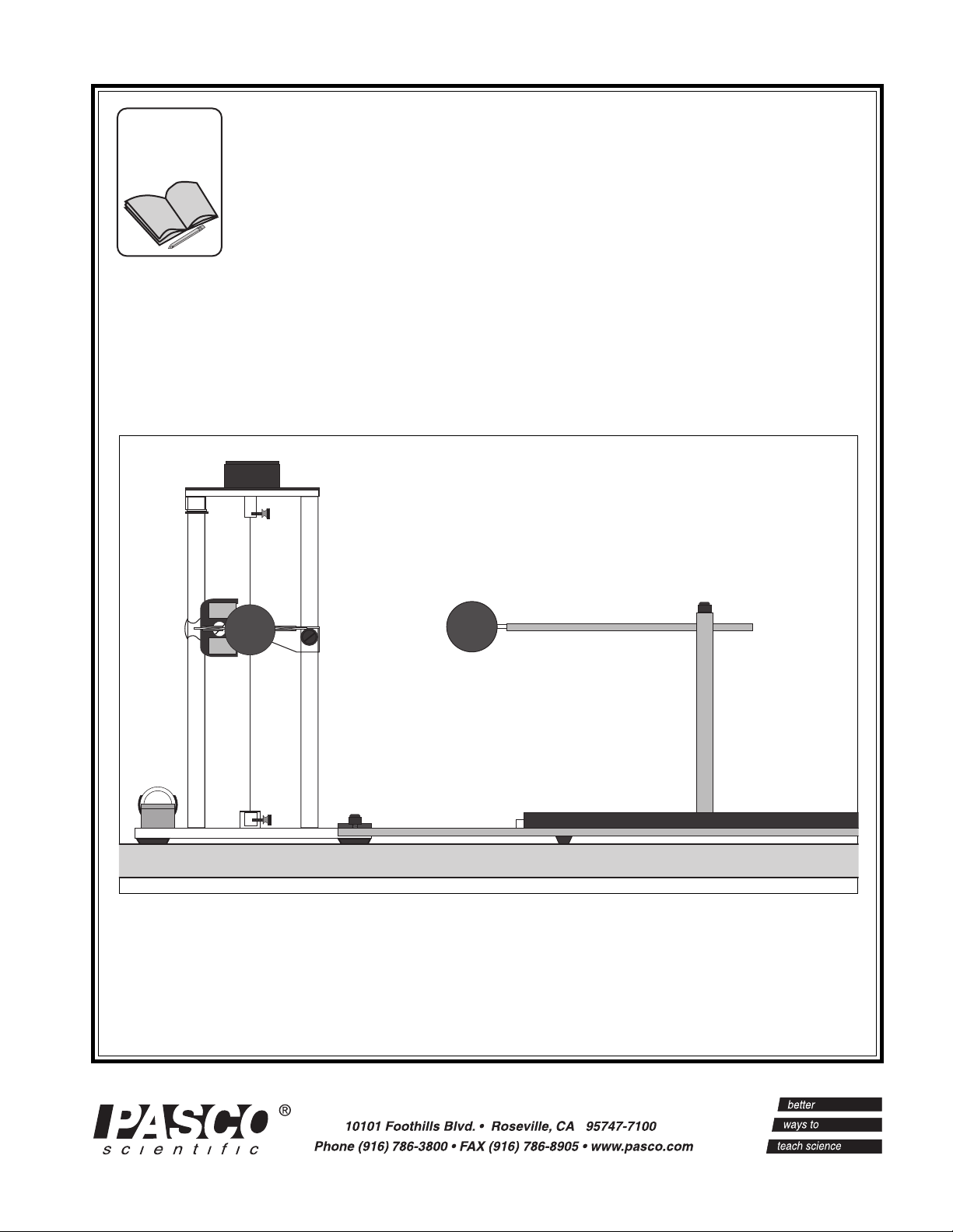
The PASCO Model ES-9070 Coulomb Balance
(Figure 1) is a delicate torsion balance that can be used to
investigate the force between charged objects. A
conductive sphere is mounted on a rod, counterbalanced,
and suspended from a thin torsion wire. An identical
sphere is mounted on a slide assembly so it can be
positioned at various distances from the suspended sphere.
To perform the experiment, both spheres are charged, and
the sphere on the slide assembly is placed at fixed
charged spheres
torsion wire
Figure 1. Experimenting with the Coulomb Balance
slide assembly
distances from the equilibrium position of the suspended
sphere. The electrostatic force between the spheres causes
the torsion wire to twist. The experimenter then twists the
torsion wire to bring the balance back to its equilibrium
position. The angle through which the torsion wire must be
twisted to reestablish equilibrium is directly proportional
to the electrostatic force between the spheres.
All the variables of the Coulomb relationship
(F = kq
/R2) can be varied and measured using the
1q2
Coulomb Balance. You can verify the inverse square
relationship and the charge dependence using the balance
and any electrostatic charging source.
However, for best results, we recommend you charge the
spheres with a stable kilovolt power supply to ensure a
reproducible charge throughout the experiment. To
determine the Coulomb constant with reasonable
accuracy, we recommend you use an electrometer and a
Faraday ice pail to accurately measure the charge on the
spheres. For more information about accuracy, read the
section Tips for Accurate Results.
1
Page 6
Coulomb Balance 012-03760E
Theory
Take one gram of protons and place them one meter away
from one gram of electrons. The resulting force is equal to
1.5 x 10²³ newtonsroughly the force it would take to
lift an object from the surface of the Earth that had a
mass about 1/5 that of the moonnot a small force.
So, if such small amounts of charge produce such
enormous forces, why does it take a very delicate torsion
balance to measure the force between charged objects in
the laboratory? In a way, the very magnitude of the forces
is half the problem. The other half is that the carriers of the
electrical forcethe tiny proton and the even tinier
electronare so small, and the electrons are so mobile.
Once you separate them, how do you keep them
separated? The negatively charged electrons are not only
drawn toward the positively charged protons; they also
repel each other. Moreover, if there are any free electrons
or ions between the separated charges, these free charges
will move very quickly to reduce the field caused by the
charge separation.
So, since electrons and protons stick together with such
tenacity, only relatively small charge differentials can be
sustained in the laboratory. This is so much the case that,
even though the electrostatic force is more than a billion-
billion-billion-billion times as strong as the gravitational
force, it takes a very delicate torsion balance to measure
the electrical force, whereas we can measure the
gravitational force by weighing an object with a spring
balance.
ä
NOTE: The torsion balance gives a direct and
reasonably accurate measurement of the Coulomb
force. The most accurate determinations of
Coulomb's law, however, are indirect. It can be
shown mathematically that if the inverse square law
holds for the electrostatic force, the electric field
inside a uniformly charged sphere must be
everywhere zero. Measurements of the field inside a
charged sphere have shown this to be true with
remarkable accuracy. The Coulomb force can be
expressed by the formula:
1q2
/R
2+n
.
F = kq
Using this indirect method, it has been demonstrated
experimentally that n 2 x 10
16
.
2
Page 7
012-03760E Coulomb Balance
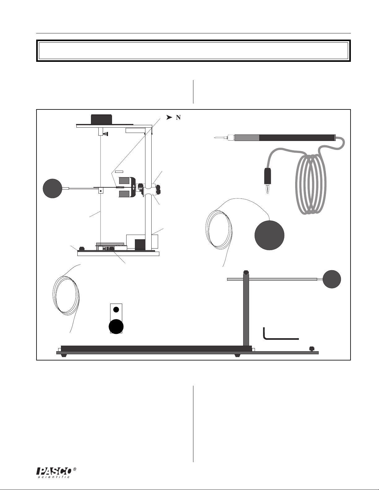
Equipment
The Coulomb Balance and the included accessories are
shown in Figure 2.
ä
be shipped with the copper
rings unattached.
COULOMB
BALANCE
torsion wire
(pendulum)
coupling
Plate
retainer
spare torsion wire
(3 meters)
toolbox with:
one 50 mg mass
two 20 mg masses
one hex key
magnetic
damping arm
index arm
calibration
support tube
(The Coulomb Balance and the slide assembly should be
shipped with one of the conductive spheres unattached.
See the Setup section of this manual.)
NOTE: The balance may
charging probe
conductive sphere on insulating
thread
torsion wire
clamp
Figure 2. The Coulomb Balance
Additional Equipment Recommended:
A stable kilovolt power supply for charging the
spheresAny electrostatic charger can be used to
charge the spheres, but a power supply lets you
replenish the charge to a fixed value throughout an
experiment. Ideally the supply would have a
momentary power on button so that you can
conveniently turn it off whenever you are not
charging the spheres.
allen wrench for the slide
assembly
slide assembly
An electrometer and Faraday ice pail (such as
PASCO Models ES-9054A and ES-9058) for
accurately measuring the charge on the spheres.
A spring balance capable of measuring a force of
approximately 4 newtons (400 gram mass). This is
not necessary for the experiment itself, but is helpful
in setting the tension of the torsion wire.
3
Page 8

Coulomb Balance 012-03760E
Tips for Accurate Results
IMPORTANT: If you live in an area where
humidity is always high, and if you have no facilities
for controlling humidity, the experiment will be
difficult, if not impossible, to perform. Static
charges are very hard to maintain in a humid
atmosphere because of surface conductivity.
Experiments with the Coulomb Balance are
straightforward and quite accurate, yet, as with any
quantitative electrostatic experiment, frustration lurks just
around the corner. A charged shirt sleeve, an open
window, an excessively humid dayany of these and
more can affect your experiment. However, if you
carefully follow the tips listed below, youve got a good
start toward a successful experiment.
Perform the experiment during the time of year when
humidity is lowest.
Perform the experiment in a draft-free room.
The table on which you set up the experiment should
be made of an insulating materialwood, masonite,
plastic, etc. If a metal table is used, image charges
will arise in the table that will significantly affect the
results. (This is also true for insulating materials, but
the effect is significantly reduced.)
Position the torsion balance at least two feet away
from walls or other objects which could be charged
or have a charge induced on them.
When performing experiments, stand directly behind
the balance and at a maximum comfortable distance
from it. This will minimize the effects of static
charges that may collect on clothing.
Avoid wearing synthetic fabrics, because they tend to
acquire large static charges. Short sleeve cotton
clothes are best, and a grounding wire connected to
the experimenter is helpful.
Use a stable, regulated kilovolt power supply to
charge the spheres. This will help ensure a constant
charge throughout an experiment.
When charging the spheres, turn the power supply
on, charge the spheres, then immediately turn the
supply off. The high voltage at the terminals of the
supply can cause leakage currents which will affect
the torsion balance. A supply with a momentary
power on button is ideal.
When charging the spheres, hold the charging probe
near the end of the handle, so your hand is as far
from the sphere as possible. If your hand is too close
to the sphere, it will have a capacitive effect,
increasing the charge on the sphere for a given
voltage. This effect should be minimized so the
charge on the spheres can be accurately reproduced
when recharging during the experiment.
If you are using a PASCO Electrometer (Model
ES-9035 or ES9054A) to measure the charge on the
spheres, connect the voltage output to a digital
multimeter so that values can be measured more
accurately. It is also useful to calibrate the
electrometer. This is done by applying a calibrating
voltage to the input and measuring the electrometer
output on the digital multimeter. Your measured
values can then be adjusted as necessary.
Surface contamination on the rods that support the
charged spheres can cause charge leakage. To
prevent this, avoid handling these parts as much as
possible and occasionally wipe them with alcohol to
remove contamination.
There will always be some charge leakage. Perform
measurements as quickly as possible after charging,
to minimize the leakage effects.
Recharge the spheres before each measurement.
4
Page 9
012-03760E Coulomb Balance
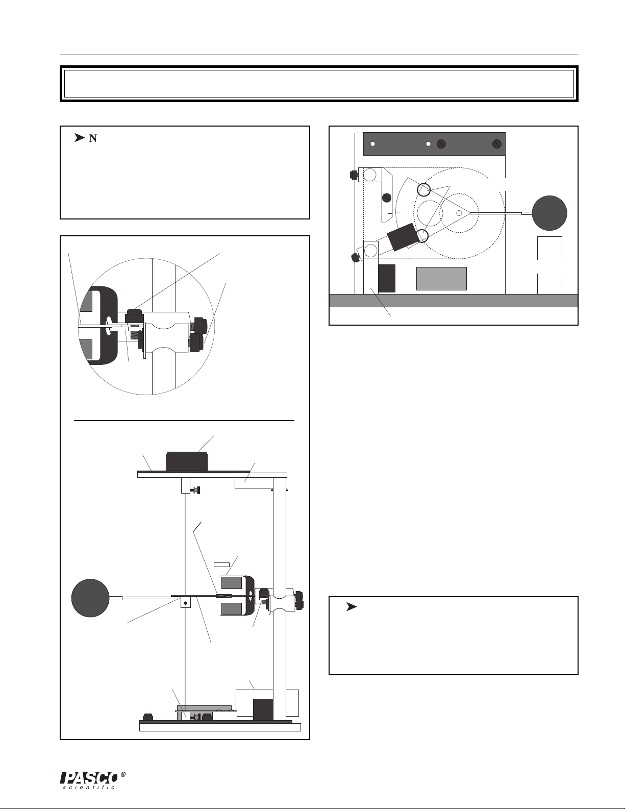
Setup
ä
Note Threading the Torsion Wire: The
Torsion Balance is shipped to you with the wire
already threaded. However, if it ever breaks,
you can thread it using the spare wire that is supplied. See the procedure at the end of this manual.
copper rings
counterweight
vane
degree scale
packing
clamp
Releasing the packing clamp
1. Loosen the top
thumbscrew
2. Loosen the side
thumbscrew and
rotate the index
arm so it is parallel
with the base of the
Coulomb Balance.
Then tighten the
thumbscrew.
torsion knob
copper rings
magnetic
damping arm
lateral support
bar
support
tube
lateral support bar
Figure 4. Zeroing the Torsion Balance
Torsion Balance Setup
➀ One of the conductive spheres is not attached when the
Coulomb Balance is shipped. To attach it, just slip the
stem of the sphere over the fiber glass rod of the
pendulum assembly.
➁ Slide the copper rings onto the counterweight vane, as
shown in the bottom of Figure 3. Then release the
packing clamp that holds the counterweight vane, as
shown in the top of Figure 3. Adjust the position of the
copper rings so the pendulum assembly is level.
➂ Reposition the index arm so it is parallel with the base
of the torsion balance and at the same height as the
vane.
pendulum
assembly
torsion wire retainer
Index arm
counterweight
vane
support tube
Figure 3. Setting Up the Coulomb Balance
ä
Important: When storing the torsion balance,
always clamp the counterweight vane to protect the
torsion wire. When you do this, be sure to adjust the
height and angle of the index arm so that you can
clamp the vane without pulling on the torsion wire.
➃ Adjust the height of the magnetic damping arm so the
counterweight vane is midway between the magnets.
➄ Turn the torsion knob until the index line for the degree
scale is aligned with the zero degree mark.
5
Page 10

Coulomb Balance 012-03760E
➅ Rotate the bottom torsion wire retainer (do not loosen
or tighten the thumbscrew) until the index line on the
counterweight vane aligns with the index line on the
index arm.
➆ Carefully turn the torsion balance on its side,
supporting it with the lateral support bar, as shown in
Figure 4. Place the support tube under the sphere, as
shown.
➇ Adjust the positions of the copper rings on the
counterweight vane to realign the index line on the
counterweight with the index line on the index arm.
➈ Place the torsion balance upright.
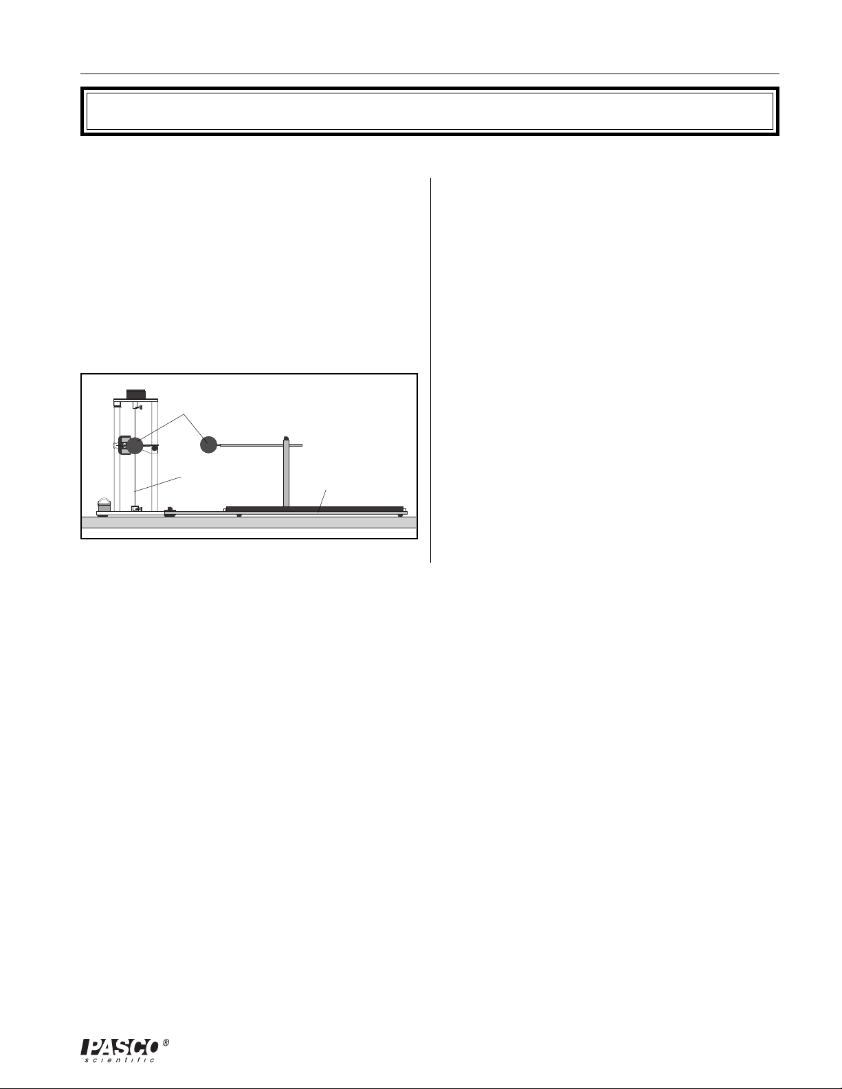
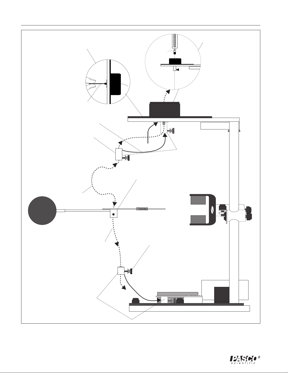
Slide Assembly Setup
(Refer to Figure 5)
➀ Connect the slide assembly to the torsion balance as
shown in Figure 5, using the coupling plate and
thumbscrews to secure it in position.
➁ Align the spheres vertically by adjusting the height of
the pendulum assembly so the spheres are aligned: Use
the supplied allen wrench to loosen the screw that
anchors the pendulum assembly to the torsion wire.
Adjust the height of the pendulum assembly as needed.
Readjust the height of the index arm and the magnetic
damping arm as needed to reestablish a horizontal
relationship.
➂ Align the spheres laterally by loosening the screw in
the bottom of the slide assembly that anchors the
vertical support rod for the sphere, using the supplied
allen wrench (the vertical support rod must be moved
to the end of the slide assembly, touching the white
plastic knob to access the screw). Move the sphere on
the vertical rod until it is laterally aligned with the
suspended sphere and tighten the anchoring screw.
➃ Position the slide arm so that the centimeter scale
reads 3.8 cm (this distance is equal to the diameter of
the spheres).
➄ Position the spheres by loosening the thumbscrew on
top of the rod that supports the sliding sphere and
sliding the horizontal support rod through the hole in
the vertical support rod until the two spheres just
touch. Tighten the thumbscrew.
You're now ready to experiment. The degree scale should
read zero, the torsion balance should be zeroed (the index
lines should be aligned), the spheres should be just
touching, and the centimeter scale on the slide assembly
should read 3.8 cm. (This means that the reading of the
centimeter scale accurately reflects the distance between
the centers of the two spheres.)
2
side view
top view
Figure 5. Slide Assembly Setup
6
1
3
5
4
Page 11

012-03760E Coulomb Balance
Experiment: (Part A) Force V ersus Distance
Procedure
➀ Set up the Coulomb Balance as described in the
suspended
sphere
previous section.
➁ Be sure the spheres are fully discharged (touch
them with a grounded probe) and move the sliding
sphere as far as possible from the suspended sphere.
Set the torsion dial to 0×C. Zero the torsion balance
by appropriately rotating the bottom torsion wire
retainer until the pendulum assembly is at its zero
displacement position as indicated by the index
marks.
pendulum
assembly
Figure 6. Experimental Setup
➂ With the spheres still at maximum separation, charge both the spheres to a potential of
6-7 kV, using the charging probe. (One terminal of the power supply should be grounded.)
Immediately after charging the spheres, turn the power supply off to avoid high voltage leakage
effects.
ä
IMPORTANT: Read the section Tips for Accurate Results. It has some helpful hints about
charging the spheres.
➃ Position the sliding sphere at a position of 20 cm. Adjust the torsion knob as necessary to balance
the forces and bring the pendulum back to the zero position. Record the distance (R) and the angle
(q) in Table 1.
sliding
sphere
slide assembly
➄ Separate the spheres to their maximum separation, recharge them to the same voltage, then
reposition the sliding sphere at a separation of 20 cm. Measure the torsion angle and record your
results again. Repeat this measurement several times, until your result is repeatable to within ± 1
degree. Record all your results.
➅ Repeat steps 3-5 for 14, 10, 9, 8, 7, 6 and 5 cm.
Analysis
ä
NOTE: In this part of the experiment, we are assuming that force is proportional to the
torsion angle. If you perform Part C of the experiment, you will test this assumption when you
calibrate the torsion balance.
Determine the functional relationship between the force, which is proportional to the torsion angle
(q); and the distance (R). This can be done in the following ways:
➀ Plot log q versus log R.
n
Explanation: If q = bR
The slope of the graph of log q versus log R will therefore be a straight line. Its slope will be equal
to n and its y intercept will be equal to log b. Therefore, if the graph is a straight line, the
function is determined.
, where b and n are unknown constants, then log q = n log R + log b.
7
Page 12

Coulomb Balance 012-03760E
B
➁ Plot q versus R
2
Either of these methods will demonstrate that, for relatively large values of R, the force is proportional to 1/R2. For small values of R, however, this relationship does not hold.
Corrections to the data
The reason for the deviation from the inverse square relationship at short distances is that the charged
spheres are not simply point charges. A charged conductive sphere, if it is isolated from other
electrostatic influences, acts as a point charge. The charges distribute themselves evenly on the
surface of the sphere, so that the center of the charge distribution is just at the center of the sphere.
However, when two charged spheres are separated by a distance that is not large compared to the size
of the spheres, the charges will redistribute themselves on the spheres so as to minimize the electrostatic energy. The force between the spheres will therefore be less than it would be if the charged
spheres were actual point charges.
A correction factor B, can be used to correct for his deviation. Simply multiply each value of q by 1/
B, where
where a equals the radius of the spheres and R is the separation between spheres.
To correct your data:
=1–4
3
a
;
3
R
➀ Calculate the correction factor B for each of the separations R that you used. Record your results in
Table 1.
➁ Multiply each of your collected values of q by 1/B and record your results as q
➂ Reconstruct your graphs relating force and separation, but this time use q
corrected
.
corrected
instead of q. Make
your new plot on the same graph as your original plot. How does the correction factor affect your
results?
(Part B) Force V ersus Charge
With the sphere separation (R) held at a constant value (choose a value between 7 and 10 cm), charge
the spheres to different values and measure the resulting force. Keep the charge on one sphere
constant, and vary the charge on the other. Then graph angle versus charge to determine the relationship.
The charge can be varied using either of two methods:
Method I:
If your power supply is adjustable, simply charge the spheres to different potentials, such as 7, 6, 5,
4, and 3 kV. (When charging the spheres, they should always be at their maximum separation.) The
charge on the sphere is proportional to the charging potential.
Method II:
If your power supply voltage is not adjustable, the charge can be changed by touching one or both of
the spheres with an identical sphere that is discharged. The charge will be shared equally between the
charged and discharged sphere. Therefore, touch the charged sphere once to reduce the charge by
half, twice to reduce the charge by 1/4, etc.
8
Page 13

012-03760E Coulomb Balance
(Part C) The Coulomb Constant
In parts A and B of this lab, you determined (if all went well) that the electrostatic force between two point
charges is inversely proportional to the square of the distance between the charges and directly proportional
to the charge on each sphere. This relationship is stated mathematically in Coulombs Law:
1q2
q
where F is the electrostatic force, q
and q2 are the charges, and R is the distance between the charges. In
1
order to complete the equation, you need to determine the value of the Coulomb constant, k. To accomplish this, you must measure three additional variables: the torsion constant of the torsion wire (K
can convert your torsion angles into measurements of force, and the charges, q1 and q2. Then, knowing F,
q1, q2, and R, you can plug these values into the
Coulomb equation to determine k.
Measuring the Torsion constant, K
F = k
;
2
R
), so you
tor
center
line
➀ Carefully turn the Torsion Balance on its side,
supporting it with the lateral support bar, as shown
copper rings
in Figure 7. Place the support tube under the
sphere, as shown.
➁ Zero the torsion balance by rotating the torsion
dial until the index lines are aligned. Record the
angle of the degree plate in Table 2.
support
tube
➂ Carefully place the 20 mg mass on the center line
of the conductive sphere.
➃ Turn the degree knob as required to bring the
lateral support bar
index lines back into alignment. Read the torsion
angle on the degree scale. Record the angle in
Figure 7. Calibrating the Torsion Balance
Table 2.
➄ Repeat steps 3 and 4, using the two 20 mg masses and the 50 mg mass to apply each of the masses shown
in the table. Each time record the mass and the torsion angle.
➅ Complete the table as follows to determine the torsion constant for the wire:
a. Calculate the weight for each set of masses that you used.
b. Divide the weight by the torsion angle to determine the torsion constant at each weight.
c. Average your measured torsion constants to determine the torsion constant for the wire. Use the
variance in your measured values as an indication of the accuracy of your measurement.
mass
ä
NOTE: A torsion constant for a wire usually expresses the torque required to twist the wire a unit
angle, and is normally expressed in newton meters per degree. However, when using the torsion balance,
the torque arm is always the same (the distance from the center of the conductive sphere to the torsion
wire), so the torsion constant for the balance is more conveniently expressed in newtons per degree.
9
Page 14

Coulomb Balance 012-03760E
Measuring the Charges, q1 and q
Method I:
The capacitance of an isolated conductive sphere is given by the equation:
where C is the capacitance, e
For a capacitor, charge (q) and charging potential (V) are related by the equation: q = CV. You can
use this equation to determine the charge on the spheres from your applied charging potential.
This is the simplest method for determining the charge on the spheres. Unfortunately, the conducting
spheres of the Coulomb Balance are not isolated in this application, so the measured values of q will
be only approximate.
ä
NOTE: A capacitor normally consists of two conductors. The charge on one conductor is +q and
the charge on the other is q. V is the potential difference between the two conductors. For an
isolated sphere with a charge +q, the second conductor is a hypothetical plane at ground potential
and with charge q, located at a distance infinitely far from the sphere.
Method II:
The charge on the spheres can be measured more
accurately using an electrometer with a Faraday ice
pail. The setup for the measurement is shown in
Figure 8. The electrometer and ice pail can be
modeled as an infinite impedance voltmeter in
parallel with a capacitor. A sphere with a charge q is
touched against the ice pail. Since the capacitance of
the ice pail and electrometer is much greater than
that of the sphere, virtually all of the charge q is
transferred onto the ice pail. The relationship
between the voltage reading of the electrometer and
the charge deposited into the system is given by the
equation q = CV, where C is the combined capacitance of the electrometer, the ice pail, and the
connecting leads. Therefore, in order to determine
the charge, you must know the capacitance of the
system.
= 8.85 x 10
0
2
p e
C = 4
12
F/m, and a = the radius of the sphere.
a;
0
Conductive sphere on an
insulating thread
Electrometer
Faraday
ice pail
The simplest way to measure the capacitance of the
electrometer and ice pail is to use a good capacitance meter connected between the inside and
Figure 8. Measuring the Charge with an
Electrometer and a Faraday Ice Pail
outside conductors of the ice pail (the electrometer
must be connected to the ice pail during the measurement). A second method is to charge a precision
capacitor with capacitance equal to C
on the capacitor is then equal to q
inside and outside conductors of the ice pail. The charge q
(³ 250 pF) to a known voltage V
test
test
= C
. Place the leads of the charged capacitor between the
testVtest
test
(10 - 30 V). The charge
test
is now distributed across two parallel
capacitors, the precision capacitor and the capacitance of the ice pail and electrometer system.
Therefore: C
testVtest
= (C + C
)V; where C is the capacitance of the electrometer and Faraday ice pail
test
and V is the voltage reading of the electrometer.
10
Page 15

012-03760E Coulomb Balance
Therefore C = C
test
(V
- V)/V. Once youve measured the capacitance C, measure the charge of
test
the charged sphere is follows:
➀ Discharge the conducting sphere on the insulating thread, by touching it to a grounded probe.
➁ Holding the sphere by the insulating thread, touch it to the charged sphere, then to the inner
conductor of the ice pail.
➂ The charge on the original charged sphere, q, can now be determined using the equation:
q = 2CV;
where C is the capacitance of the electrometer and ice pail and V is the reading on the electrometer. (The factor of two arises because, in using the test sphere to sample the charge on the
original sphere, only half the original charge was transferred.)
Calculations for the Coulomb Constant
The Coulomb constant can now be determined by using any data pair from your force versus
distance data.
➀ Convert your torsion angle measurement (q
torsion constant for the torsion wire: F = K
) to a force measurement, using your measured
corrected
torqcorrected
.
➁ Determine the charge that was on the sphere using Method I or Method II above. If you are using
Method II, you will need to recharge the sphere to the voltage previously used while taking data,
so that you can determine the charge using the electrometer and the Faraday ice pail.
➁ Plug your collected data into the Coulomb equation, F = k q
/R2, to determine the value of k.
1q2
Do this for several sets of data. Average your results to determine a value for k.
11
Page 16
Coulomb Balance 012-03760E
Table 1. Force versus Distance
Data and Calculations
1 - 4a
B
3/R3
qq
R
avg
q
corrected
1/R
2
m
0 mg
20 mg
40 mg
50 mg
70 mg
Table 2. Force Calibration
Data and Calculations
q
mg
mg/q
Torsion constant = K
Table 3. The Charge on the Sphere
tor
C (Capacitance of Electrometer System) =
V (Electrometer Voltage) =
q (Charge on sphere) = 2CV =
12
Page 17
012-03760E Coulomb Balance
Replacing the T orsion Wire
To replace the torsion wire, follow the numbered steps
in Figure 9. When you're done, follow the instructions
in the Setup section of this manual to balance the pendulum and to zero the torsion balance.
ä
IMPORTANTWhen Replacing the
Wire:
➀ Begin with a length of wire at least 50 cm
long (if you've done this before, you may not
need such a long piece).
➁ Be careful not to kink the wire.
➂ As you thread the wire, the end may become
bent or kinked. It will help to clip the end off
so it remains straight.
➃ Tighten the screws that hold the torsion wire
gently. Overtightening will break the wire.
➄ The tension on the torsion wire is not a
critical variable, as long as the wire is
reasonably taut. The advantage of the spring
balance is that it helps you adjust the tension,
without pulling too hard and breaking the
wire. If you don't have a spring balance, you
can adjust the tension by feel. Just take care
not to break the wire.
13
Page 18
Coulomb Balance 012-03760E
5. a. Carefully lay the torsion
balance on its side.
b. Thread the wire through
the hole in the torsion
knob. It is helpful to hold
the thread against the
small allen wrench,
pushing them through
together, as shown.
allen wrench
4. Thread the wire
through the washer.
3. a. Remove the wire retainer by
unscrewing it.
b. Loosen the set screw and
thumbscrew one full turn.
c. Thread the wire in the
direction shown.
d. Retighten the set screw, but
do not tighten the thumbscrew. The wire must be
able to turn.
Torsion wire
8. a. Using the torsion wire
clamp and a spring
balance, pull the wire
with a force of
approximately 4
newtons (400 gram
mass).
b. Tighten the thumb-
screw.
7. Screw the wire
retainer back in
place.
9. Adjust the height of
the pendulum assembly, then tighten the
set screws with the
allen wrench.
1. a. Use the allen wrench to
loosen both set screws
one full turn.
b. Thread the wire in the
direction shown.
c. Do not tighten the screws.
6. Put the lower wire retainer
back in position, sliding the
wire through the slot in the
bottom bracket.
2. a. Using the allen wrench,
loosen the set screw one
full turn.
b. Loosen the thumbscrew
one full turn.
c. Thread the wire in the
direction shown.
d. Tighten both screws.
Figure 9. Replacing the Torsion Wire
14
Page 19
012-03760E Coulomb Balance
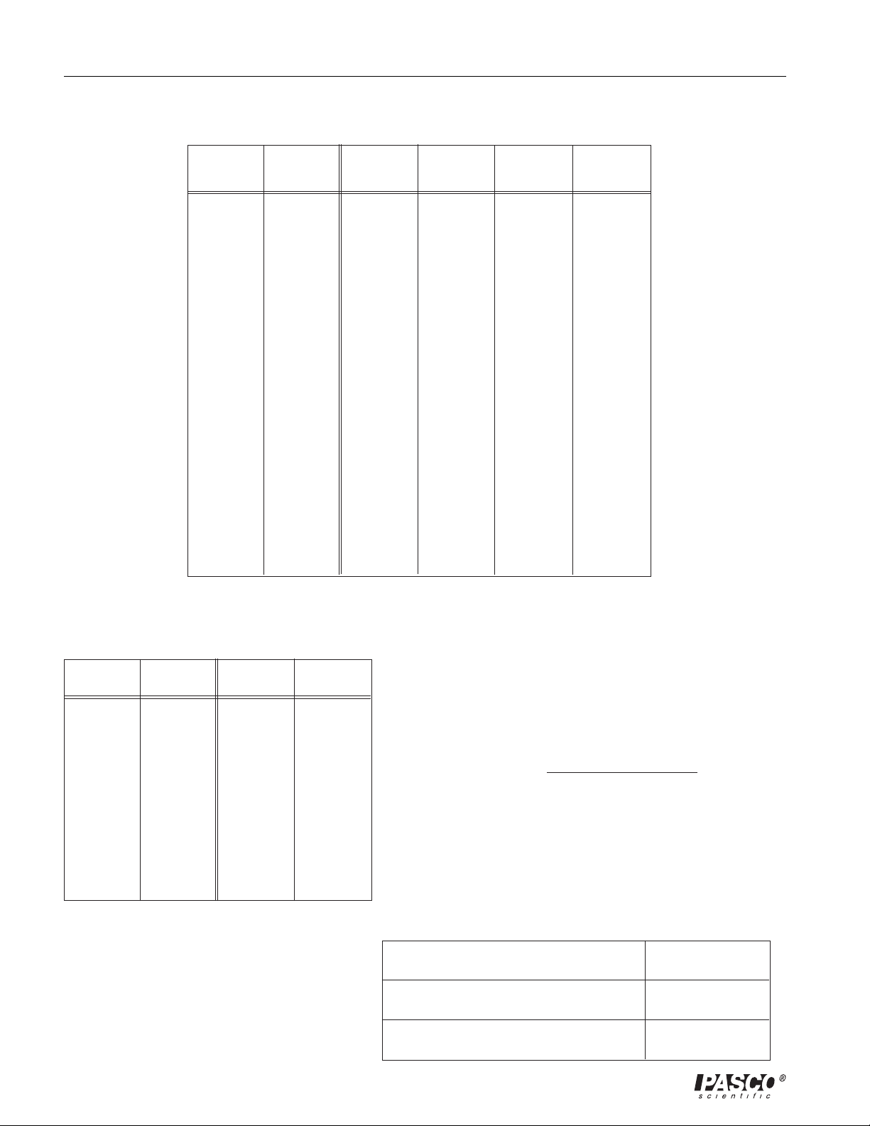
Teacher’s Guide
Experiments: Parts A-C
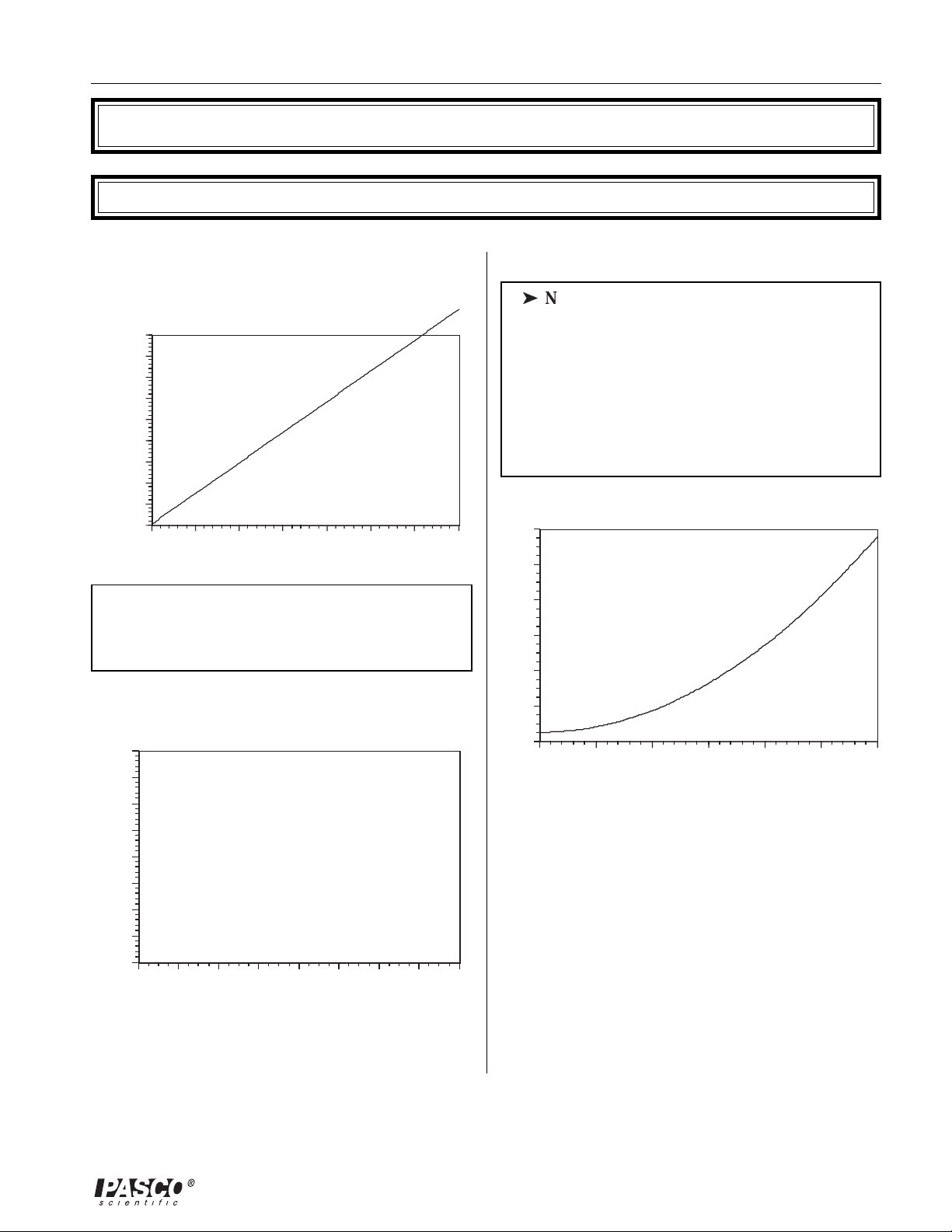
Torsion Wire Calibration
0.0009
0.0008
0.0007
0.0006
0.0005
0.0004
Force (N)
0.0003
0.0002
0.0001
J
0
0 100 200 300 400 500 600 700
J
J
J
f(x) = 1.448574E-6*x + 4.496489E-6
R^2 = 9.998832E-1
Angle (degrees)
J
➤ NOTE: The slope of this curve is dependent
on the tension on the wire; thus, it will be slightly
different for each unit.
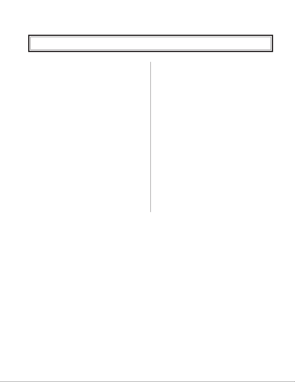
Distance Dependence
Charge Dependence
ä
NOTE: There are two ways of verifying the
J
dependence of force on charge. You may hold
one of the spheres at a constant charge and show
that force is linear with the other charge, or you
may charge both spheres equally and show that
the force is proportional to the square of the
charge. The latter method is easier to control with
a single voltage supply, and was used for this
write-up.
120
f(x) = 1.335407E-5 * (x^1.836206E+0 )
R^2 = 9.954969E-1
100
y= 3.071653E-6*x^2+4.956344E+0;
R^2 = 9.967336E-1
80
60
Angle (degrees)
40
20
J
J
J
J
J
J
J
J
J
400
350
300
250
200
Angle
150
100
50
0
0246810121416
5
f(x) = 3.994733E+3 * (x^-1.749366E+0 )
R^2 = 9.959050E-1
5
5
5
5
5
5
Distance (cm)
5
5
5
5
A power regression of this data shows that there is
an inverse-square dependence, as predicted by
theory.
0
0 1000 2000 3000 4000 5000 6000
Potential (V)
The first equation given here (a power regression)
shows that the force is dependent on the square of
the charges, as predicted by the equations.
The second curve fit (a programmed least-squares
fit), when converted to SI units, gives us a value of
5
5
1.05x10
accepted value of 9 x 10⁹. We do not know the
10
for k. This value is 17% higher than the
reason for this error at the time this is being written.
If you have any explanations for this error, or
suggestions about how to improve it, please let us
know. Call PASCO Technical support at (800) 772-
8700.
15
Page 20

Coulomb Balance 012-03760D
Notes
16
Page 21
T echnical Support
Feedback
If you have any comments about the product or manual,
please let us know. If you have any suggestions on
alternate experiments or find a problem in the manual,
please tell us. PASCO appreciates any customer
feedback. Your input helps us evaluate and improve our
product.
To Reach PASCO
For technical support, call us at 1-800-772-8700
(toll-free within the U.S.) or (916) 786-3800.
fax: (916) 786-3292
e-mail: techsupp@pasco.com
web: www.pasco.com
Contacting Technical Support
Before you call the PASCO Technical Support staff, it
would be helpful to prepare the following information:
➤ If your problem is with the PASCO apparatus, note:
Title and model number (usually listed on the
label);
Approximate age of apparatus;
A detailed description of the problem/sequence of
events (in case you can’t call PASCO right away,
you won’t lose valuable data);
If possible, have the apparatus within reach when
calling to facilitate description of individual parts.
➤ If your problem relates to the instruction manual,
note:
Part number and revision (listed by month and
year on the front cover);
Have the manual at hand to discuss your
questions.
Page 22

 Loading...