

Page 1
Instruction Manual
Manual No. 012-08455A
Charge,
Equipotential and
Field Mapper
Model No. ES-9060
Page 2

Page 3

Table of Contents
Equipment List........................................................ 3-4
Introduction ............................................................. 5
Equipment Setup .................................................... 6-10
Part I: Sketching the Charged Paths........................................................................................... 6-7
Part II: Connecting the Electrodes to a Power Supply and Checking their Potential ................ 7-8
Part III: Plotting an Equipotential .............................................................................................. 8-9
Part IV: Plotting Field Gradients ............................................................................................. 9-10
Equipotential and Field Mapping Experiments ....................11-15
Experiment 1: Parallel Plate Capacitor ........................................................................................11
Experiment 2: Point Source and Guard Ring...............................................................................11
Experiment 3: Dipoles of Opposite Charge.................................................................................12
Experiment 4: Dipoles of Like Charge ........................................................................................12
Experiment 5 :Floating Electrode ................................................................................................12
Experiment 6: Floating Insulator .................................................................................................13
Experiment 7: Line and Circular Source......................................................................................13
Experiment 8: Line and Sharp Point............................................................................................13
Experiment 9: Triode ...................................................................................................................14
Experiment 10: Fluid Mechanisms ..............................................................................................14
Charge Mapping Experiments ......................................16-21
Experiment 1: Charge Density Inside and Outside a Cylinder .............................................. 18-19
Experiment 2: Charge Density on a Cone.............................................................................. 19-20
Experiment 3: Charge Density on a Plane near a Point Source ............................................. 20-21
Appendix A: Technical Support .......................................22
Appendix B: Copyright and Warranty Information ..................22
2
®
Page 4
Model No. ES-9060 Charge, Equipotential, and Field Mapper
Charge, Equipotential
and Field Mapper
Model No. ES-9060
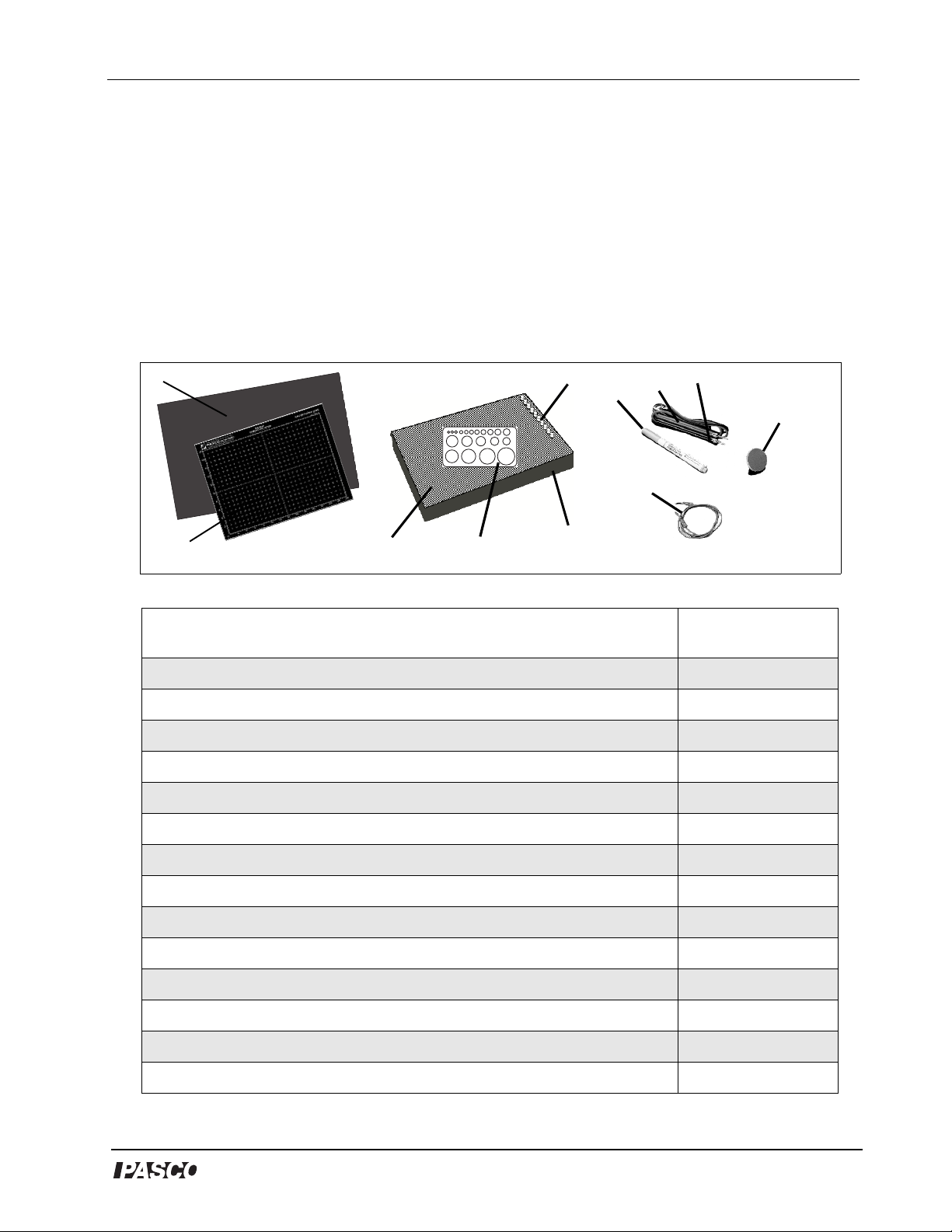
Equipment List
1
2
Included Equipment Replacement
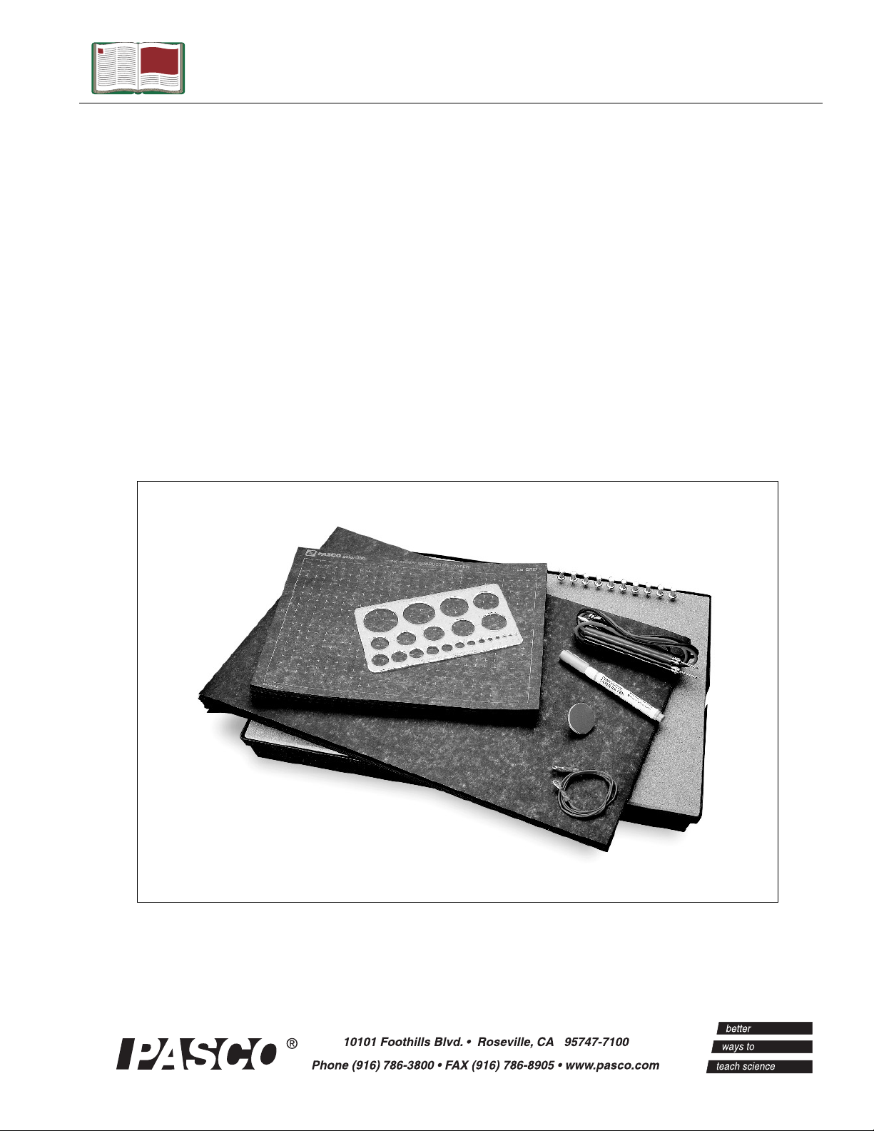
1. Conductive paper, plain, 45 x 30 cm (no grid) (50 sheets)
2. Conductive paper, black, 23 x 30 cm (with grid) (50 sheets)
3. Corkboard working surface, 32 x 48 cm (1)
4. Circle template for drawing the conductive paths (1)
5. Large plastic tray for storing the paper and supplies (1)
3
4
6
5
7
10
9
8
Model Number*
646-01214
PK-9025
648-02015
699-001
648-02014
11
6. Push pins for attaching the paper to the board (10)
7. Conductive Ink Pen (for approximately 60 m of continuous line) (1)
8. Probe, red lead (1)
9. Probe, black lead (1)
10. Wire, test lead, red, 18 awg (1)
11. Point Charge Disk (with blue charge pad) (1)
12. Instruction sheet for PK-9025 Conductive Paper (1) (not shown)
13. Instruction sheet for PK-9031B Conductive Ink Pen (1) (not shown)
14. Safety sheet for PK-9031B Conductive Ink Pen (not shown)
®
699-002
PK-9031B
517-022
517-023
710-032
003-02018
012-04371
012-04297
012-04298
3
Page 5
Charge, Equipotential, and Field Mapper Model No. ES-9060
*Use Replacement Model Numbers to expedite replacement orders.
Additional Equipment Recommended (for Equipotential and Field
Gradient Experiments)
Voltmeter or Digital Multimeter (10 M or higher)
Ω
Electrostatics Voltage Source, DC Power Supply, or Battery
Additional Equipment Recommended (For Charge Mapping
Experiments
Conductive Paper without grid, 30 cm x 46 cm (100 sheets)
Electrometer
Proof Plane
Electrostatics Voltage Source or DC Power Supply
Faraday Ice Pail
Replacement
Model No.
ES-9078 or SE-9589
ES-9077
Replacement
Model No.
PK-9026
ES-9078
ES-9057B
ES-9077
ES-9042A
4
®
Page 6
Model No. ES-9060 Charge, Equipotential, and Field Mapper
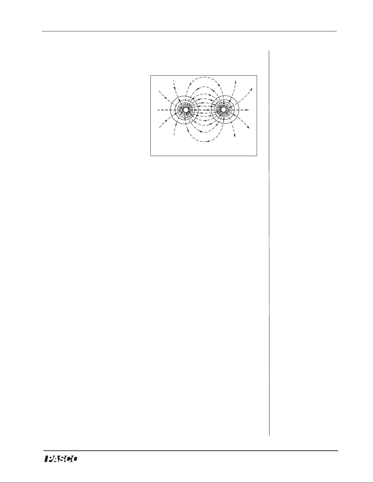
Introduction
The PASCO scientific model
ES-9060 Equipotential,
Charge and Field Mapper
consists of two basic
elements. The first is a
-
carbon impregnated paper in
the resistance range of 5 to 20
Ω
K per square. This paper
forms the conducting medium
or space between the
Figure 1: Equipotential Lines
electrodes. The second
element is a conductive ink dispensed from a pen. The ink is produced
from silver particles in a suspension liquid. As the ink dries, the silver
flakes settle on top of each other forming a conductive path (or
conductive ink electrodes). The resistance of the ink is between 0.03
and 0.05 /cm for a 1 mm wide line.
Ω
+
Because the paper has a finite resistance, a current must flow through it
to produce a potential difference. This current is supplied by the
conductive ink electrodes, which causes a potential drop to occur
across the paths. Because of the large difference between the ink’s
resistance and the resistance of the paper, this potential drop is less
than 1% of that produced across the paper. Therefore, for all practical
purposes, the potential drop across the electrodes may be considered
negligible.
To plot equipotentials, charge and field gradients with the ES-9060
Equipotential, Charge and Field Mapper, you will need a voltmeter or
other charge potential measuring device. It would be desirable that the
potential measuring instrument have an infinite impedance. An
electrometer, such as the PASCO Model ES-9054B (or ES-9078)
would be optimal; however, a standard electronic voltmeter, such as
PASCO’s SE-9589 Handheld Digital Multimeter with a 10 M (or
Ω
higher) input impedance is sufficient. Since the impedance of a 10
Ω
M voltmeter is at least 100 times greater than that of the paper, the
greatest distortion of the field which can be produced by the voltmeter
is approximately 1%.
®
5
Page 7
Charge, Equipotential, and Field Mapper Model No. ES-9060
Equipment Setup
Part I: Sketching the Charged Paths (Electrodes)
NOTE: The silver conductive ink reaches its maximum conductivity
after 20 minutes of drying time. For optimal results, plan the time
table for conducting the experiments and correlate drawing the
conductive paths accordingly.
1. Plan and sketch the layout (size, shape, and relative spacing) of the
charged path to be studied on a piece of paper. These paths can be any
two dimensional shape, such as straight or curved lines, circles, dots,
squares, etc. Since the charged paths will actually be conductive ink
electrodes, they will be referred to as electrodes.
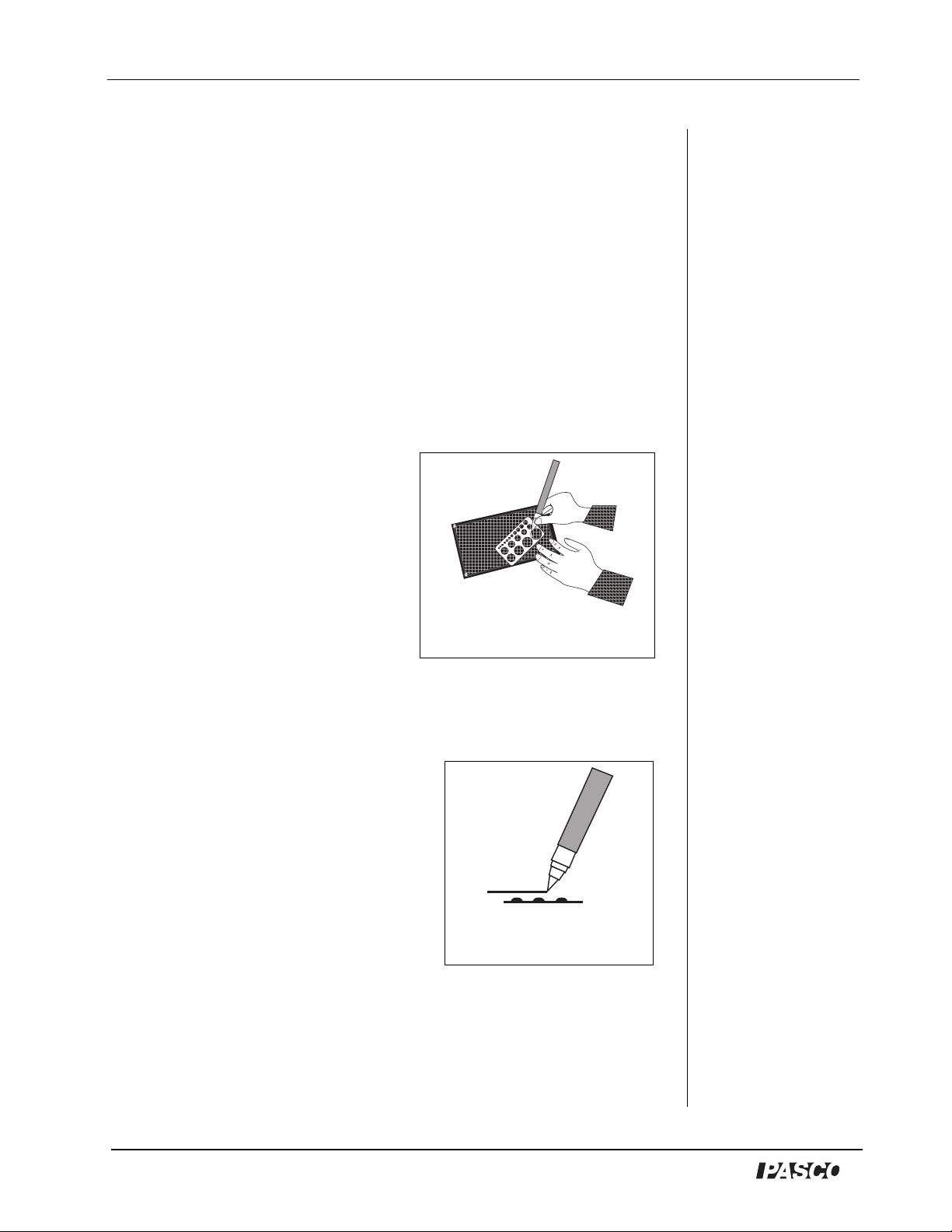
2. Draw the electrodes on the black
paper (See Figure 2).
NOTE: This next steps (a-e) are the
most difficult and crucial part of the
experiment. Follow these steps
carefully.
a) Place the grid conductive paper
printed side up, on a smooth hard
Figure 2: Drawing
electrodes on black paper
surface. Do not attempt to draw
the electrodes while the paper is on the corkboard.
b) Vigorously shake the conductive ink pen (with the cap on) for 10-20
seconds to disperse any particle matter suspended in the ink.
c) Remove the cap. On a piece of scrap
paper, press lightly down on the
spring-loaded tip while squeezing
the pen barrel firmly. This starts the
ink flowing. Slowly drawing the
pen across the paper produces a
solid line. Drawing speed and
exerted pressure determines the path
width (See Figure 3).
Figure 3: Drawing on the
conductive paper
d) Once a satisfactory line is produced
on the scrap paper, draw the electrodes on the grid of the black
conductive paper. If the line becomes thin or spotty, draw over it
again. A solid line is essential for good measurements.
6
®
Page 8
Model No. ES-9060 Charge, Equipotential, and Field Mapper
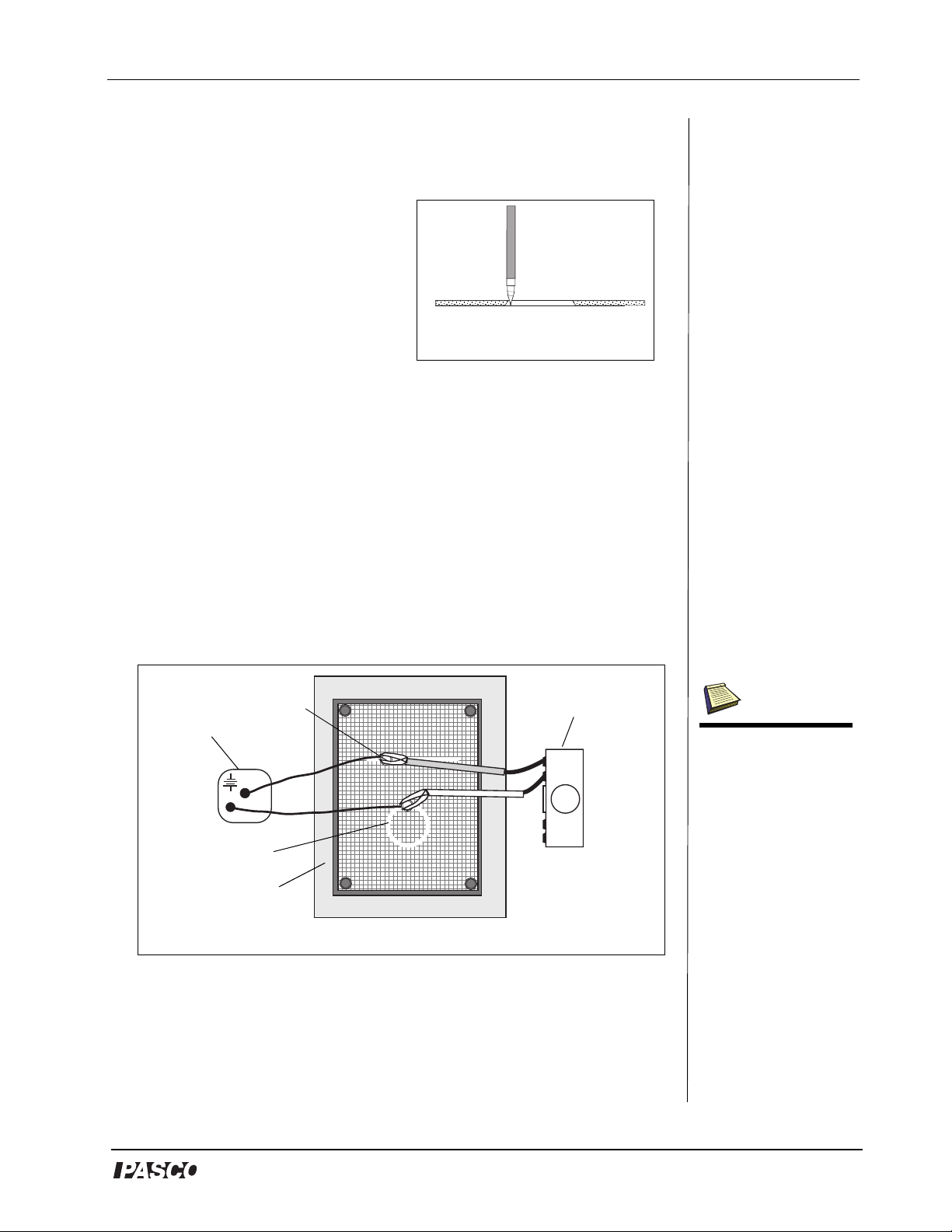
The line will be air dry in 3-5 minutes at room temperature. However,
the medium won’t reach maximum conductivity until after 20 minutes
drying time.
e) A plastic template is included
with the PASCO Field Mapper
for drawing circles (See Figure
4). Place the template on the
conductive paper and draw the
circles with the conductive ink
pen. (If desired, you may first
Figure 4: Drawing over the
template
draw the circle template with a
soft lead pencil and trace over the
pencil line with the ink.)
3. Mount the conductive paper on the corkboard using one of the
metal push pins in each corner.
Part II: Connecting the Electrodes to a Power Supply and
Checking their Potential
1. Using the supplied connecting wires, connect the electrodes to a
battery, DC power supply, or any other potential source in the 5 to 20
VDC range (See Figure 5). The potential source should be capable of
supplying 25 mA. (If possible, the potential should be equal to the full
scale reading of the electronic voltmeter used in the experiment.)
DC Power
push pin
Supply
electrode
corkboard
Figure 5: Connecting Electrodes to a Power Supply and Voltmeter
Voltmet er
M
2. Place the terminal of a connecting wire over the electrode, then
stick a metal push pin through its terminal and the electrode into the
Note: The Voltmeter used
must meet the following
specifications: a) be at
least 10 M or higher
and b) have a range
which is equal to or
higher than the potential
used across the electrodes. Any commercial
voltmeter, either analog
or digital, is adequate.
The PASCO ES-9078
Electrometer or the SE9589 Digital Multimeter
are recommended.
Ω
®
7
Page 9

Charge, Equipotential, and Field Mapper Model No. ES-9060
corkboard. Make certain the pin holds the terminal firmly to the
electrode (See Figure 6).
connecting wire
paper
Figure 6: Electrode with connecting wire
push pin
electrode
NOTE: Check to see that the terminal which touches the electrode is
clean. A dirty path may result in a bad contact.
3. Connect the other end of the wire to the battery.
4. To check the electrodes for proper conductivity, connect one
voltmeter lead near the push pin on an electrode. Touch the
voltmeter’s second lead to other points on the same electrode. If the
electrode has been properly drawn, the maximum potential between
any two points on the same electrode will not exceed 1% of the
potential applied between the two electrodes.
NOTE: This test can only be made if the potential source is connected
across the two electrodes.
If the voltage across the same electrode is greater than 1% of the
voltage applied between the two electrodes, then remove the paper
from the corkboard and draw over the electrodes a second time with
the conductive ink.
Part III: Plotting an Equipotential
Equipotentials are plotted by connecting one lead of the voltmeter
(ground) to one of the electrode push pins. This electrode now
becomes the reference. The other voltmeter lead (the probe) is used to
measure the potential at any point on the paper simply by touching the
probe to the paper at that point.
1. To map an equipotential, move the probe until the desired potential is
indicated on the voltmeter.
2. Mark the paper at this point with a soft lead or light-colored lead
pencil.
8
®
Page 10

Model No. ES-9060 Charge, Equipotential, and Field Mapper
3. Continue to move the probe, but only in a direction which
maintains the voltmeter at the same reading. Continue to mark
these points.
4. Connect the points to produce an equipotential line.
Part IV: Plotting Field Gradients
To plot field gradients (field lines), you will place the two leads of the
voltmeter on the conductive paper, side-by side, at a set distance of
separation (one centimeter is a useful separation to use). (Note: When
plotting field gradients, neither lead of the voltmeter is connected to an
electrode.) It is best to tape two leads of the voltmeter together for this
procedure (See Figure 7). The technique is to use the voltmeter leads
to find the direction from an electrode that follows the path of greatest
potential difference from point to point.
NOTE: Do not attempt to make measurements by placing the leads on
the grid marks on the conductive paper. Touch the voltmeter leads
only on the solid black areas of the paper. It may be necessary to use a
higher voltmeter sensitivity for this measurement than was used in
measuring equipotentials.
Ta p e
Conductive
paper
Area to probe
to find the highest
potential difference
Figure 7: Using the probe to find the highest
potential
Ground lead
for voltmeter
Electrode to
voltage source
(battery or
power supply)
1. To plot the field lines on the conductive paper, place the voltmeter lead
(connected to ground) near one of the dipoles.
2. Place the other voltmeter lead on the paper and note the voltmeter
reading.
3. Now pivot the lead to several new positions while keeping the
ground lead stationary (See Figure 7). Note the voltmeter readings
as you touch the lead at each new spot on the paper.
®
9
Page 11

Charge, Equipotential, and Field Mapper Model No. ES-9060
4. When the potential is the highest, draw an arrow on the paper from
the ground lead to the other lead (See Figure 8). Then move the
ground lead to the tip (head) of the arrow. Repeat the action of
pivoting and touching the front lead until the potential reading in a
given direction is highest.
Figure 8: Moving the leads over the arrow
5. Draw a new arrow. Repeat the action of putting the ground lead at
the tip (head) of each new arrow and finding the direction in which
the potential difference is highest. Eventually, the arrows drawn in
this manner will form a field line.
6. Return the dipole and select a new point at which to place the
voltmeter’s ground lead. Again, probe with the other lead until you
find the direction of highest potential difference.
7. Draw an arrow from the ground lead to the other lead, and repeat
the process until a new field line is drawn. Continue selecting new
points and drawing field lines around the original dipole (See
Figure 9).
1st line
Dipole
2nd line
Figure 9: Example of 3 field lines between unlike dipoles
Dipole
3rd line
10
®
Page 12

Model No. ES-9060 Charge, Equipotential, and Field Mapper
Equipotential and Field Mapping
Experiments
The following are only some suggested experiments in mapping
equipotentials and field gradients using the PASCO Field Mapper. The
true value of the equipment lies in its complete flexibility, permitting
the user to design any system of charged bodies, and then to map the
equipotentials and field gradients.
NOTE: Only power supply connections are shown in the following
schematics. Voltmeter connections are not shown because they vary
depending on whether equipotentials or field gradients are being
mapped.
Experiment 1: Parallel Plate Capacitor
Questions:
a) What is the field outside the
capacitor plates?
b) How does the ratio of the plate
length (l) versus separation (d)
affect the fringing effect at the edges
of the plates?
electrodes
d
connecting wires
Schematic 1
l
+
DC
source
c) What redesign of the plates, or perhaps the extra electrodes, could
help eliminate the fringing effect?
Experiment 2: Point Source and Guard Ring
Questions:
a) What relation can be derived
between the distance from the
center of the point source and the
equipotential value?
b) Would this same relation hold if the
Schematic 2
system were three dimensional?
c) What purpose does the large outer ring serve in this experiment?
+
®
11
Page 13

Charge, Equipotential, and Field Mapper Model No. ES-9060
Experiment 3: Dipoles of Opposite Charge
Questions:
a) What is the relation between the
direction of a maximum value field
+
gradient and equipotential line at
the same point? (A geometrical
relation is desired.)
b) What effect does the finite size of
the black paper have on the field?
Experiment 4: Dipoles of Like Charge
Questions:
a) How does the field of this
configuration compare with
dipoles of opposite charge? (See
Experiment 3, “Dipoles of
Opposite Charge.”)
b) What distortion of the field is
produced by the large electrode
around the perimeter of the paper?
Experiment 5: Floating Electrode
Before drawing the circular electrode,
map the equipotentials of the two
straight electrodes. Draw the circular
electrode and again map the
equipotentials.
Schematic 3
+
Schematic 4
+
Questions:
a) How does the circular electrode
Schematic 5
distort the field?
b) What is the potential of the circular electrode? Of the area inside
the electrode?
c) What effect would moving the circular electrode have?
12
®
Page 14

Model No. ES-9060 Charge, Equipotential, and Field Mapper
Experiment 6: Floating Insulator
Before cutting the rectangular
insulator, map the equipotentials of
the two straight electrodes. Cut out a
rectangular section of the paper and
again map the equipotentials.
Questions:
a) How does the rectangular insulator
distort the field?
b) What effect would moving the
rectangular insulator have?
Experiment 7: Line and Circle Source
Draw only the line and point source
“a.” Map the equipotentials. Add
circular electrode “b” and again map
the equipotentials. Add circular
electrode “c” and again map the
equipotentials.
rectangular cut-out
Schematic 6
b
a
c
+
+
Questions:
Schematic 7
a) How is the spacing of the
equipotentials affected by increasing the diameter of the circular
electrode?
Experiment 8: Line and “Sharp” Point
Before drawing the two electrodes
marked “a”, map the equipotentials.
Add the electrodes “a” and again map
a
the equipotentials.
Questions:
a) What effect did adding the extra
electrodes have on the spacing of the
a
Schematic 8
equipotentials (field strength) around
the point?
b) Why did the field strength change, even though the radius of the
point did not change?
+
®
13
Page 15

Charge, Equipotential, and Field Mapper Model No. ES-9060
Experiment 9: Triode
Equipment required: 5 K
Potentiometer
Potentiometer
Use a 5 K Potentiometer to provide
5K
a
three potentials. Connect the three
short electrodes with wires “a.”
a
Do not let these wires touch the
black paper except at the
conductive ink electrodes.
Schematic 9
Questions:
a) How is the field in the area between the short electrodes affected by
the potential between the short electrodes and the closer, long
electrode?
b) Could this paper model of a triode act as an amplifying device? If
not, why not?
Experiment 10: Fluid Mechanics Experiments
The PASCO Field Mapper can also be used to examine fluid flow. In
many fluid systems, the velocity potential satisfies the Laplace
equations (so does the electromagnetic potential). Consequently, there
is a direct analogy between fluid flow and electric fields. In particular,
the velocity potential of an incompressible fluid where the flow is both
steady and not rotational satisfies the Laplace equation. A steady flow
of water is a good approximation of this type of flow. Now the flow is
generated by “sources” which supply the fluid and “sinks” which
absorb the fluid. We are interested in “streamlines,” which can be
thought of as lines traced out by a particular particle in the fluid. The
streamlines begin at the sources and end at the sinks.
+
With the Field Mapper, we need to
draw electrodes in the shape of the
sources and sinks in the fluid flow
to be examined. Then the electric
cut-out
shape
field lines which we plot coincide
with the streamlines in the fluid
flow. (Remember that the electric
field lines are perpendicular to the
equipotential lines.) If there is
Schematic 10
some fixed obstruction in the fluid
flow, we can represent it by cutting the same shape from the
conductive paper. The schematic drawing shows a fluid flow which is
analogous to the flow in a section of pipe (with frictionless walls). The
14
+
-
®
Page 16

Model No. ES-9060 Charge, Equipotential, and Field Mapper
source is a straight line at the left, the sink is a straight line at the right.
The tear-drop shaped section cut out of the middle is some obstruction.
The field lines are the corresponding streamlines.
Procedure:
To use the Field Mapper to examine field flows, follow these steps.
1. Make sure that the fluid is incompressible and the flow is not rotational
and steady.
2. Draw the electrodes on the conductive paper in the same shape and
position as the sources and the sinks in the flow.
3. Cut out the sections of the conductive paper in the same shape and
position as the obstructions in the fluid.
4. Connect a battery between the sources and the sinks. All sources
should be connected to the same side of the battery. All sinks
should be connected to the opposite side.
5. Plot the equipotentials and draw lines perpendicular to these. You
can also pick any point and determine the direction of the
maximum field gradient. This is the direction of the streamlines at
that point.
®
15
Page 17

Charge, Equipotential, and Field Mapper Model No. ES-9060
Charge Mapping Experiments
The purpose of a charge mapping experiment is to investigate the way
charge is distributed over a surface by measuring variations in charge
density. A charged surface will be sampled with a proof plane. The
proof plane will be inserted inside the Faraday Ice Pail to measure the
charge. By sampling different sections of the surface, the relative
charge density can be observed. For example, you may find that the
amount of charge on two equal sized regions on the surface of a
conductor may differ in magnitude or even in sign. This occurs for
non-uniform charge distribution. Alternately, you may observe that
everywhere on the surface the charge has the same magnitude and
sign. This occurs for uniform charge distribution.
An important aspect of measuring charge distributions is charge
conservation. The proof plane removes some charge from the surface
it samples. If the proof plane is grounded after each measurement, the
surface will be depleted of charge with consecutive measurements.
However, by not grounding the proof plane (and by not letting it touch
the ice pail), the charge on the surface is not depleted. That charge
which the proof plane removed for one measurement is always
returned to the surface when the next sampling is made.
The Proof Plane
As shown in Figure 10, the
proof plane is an aluminumcovered conductive disk
attached to an insulated
aluminum surface
non-conductive neck
(white)
handle. The conductive disk
material is carbon-filled black
3
polycarbonate (about 10
Ω)
handle
conductive disk
(black)
with an aluminum disk. The
nonconducting neck is white
14
polycarbonate (about 10
Ω).
Figure 10: Proof Plane
The proof plane is used to sample the charge density on charged
conductive surfaces. A Faraday Ice Pail can then be used to measure
the charge density on the proof plane.
16
®
Page 18

Model No. ES-9060 Charge, Equipotential, and Field Mapper
By touching the proof plane
to a surface, the proof plane
will acquire the same charge
distribution as the section of
the surface it touched (See
charge in proof
plane equals charge
in sampled area
+
+
+
+
+
+
+
+
+
+
+
+
+
+
+
+
+
+
+
+
+
+
+
+
Figure 11). By measuring
the charge on the proof
plane, the charge density on
area sampled
that part of the surface can
be determined. The greater
the charge on the proof
Figure 11: Conductive Sphere
plane, the greater the charge
density on the surface where the proof plane made contact.
When a proof plane is touched to a conductive surface, the proof plane
becomes part of the conductive surface. If the effect on the shape of the
surface is significant, the sampling of the charge density will not be
accurate. Therefore, always touch the proof plane to the conductor in
such a way as to minimize the distortion of the shape of the surface.
Figure 12 shows the recommended method for using the proof plane to
sample charge on a conductive sphere.
NOTE: The proof planes can be used to test for charge polarity on
conductors of any shape. However, if you want accurate readings of
charge density, the conductor surface sampled has to be considerably
larger than the disk of the proof plane and have a relatively large radius
of curvature at the point of contact.
charge conductive
spheres
surface of the proof
plane IS NOT tangent
to the surface of the
conductor
Figure 12: Proper use of a Proof Plane to Sample Charge
+
+
+
+
+
+
+
+
+
+
+
+
+
+
+
+
surface of the proof
plane IS tangent
+
to the surface
+
of the conductor
+
+
+
®
17
Page 19

Charge, Equipotential, and Field Mapper Model No. ES-9060
Experiment 1: Charge Density Inside and on the
Surface of a Cylinder
Equipment Required:
Charge Mapping Apparatus ES-9060) Electrometer (ES-9078)
Proof Plane (ES-9057B) Electrostatic Voltage Source (ES-9077)
Faraday Ice Pail (ES-9042A)
lead
Electrometer
red
lead
black
Proof Plane
Ice Pail
shield
Cylinder
Power suppl y
2000 V
to COM port
Figure 1.0: Experiment Setup with Cylinder
Procedure:
1. Connect the Electrometer, outer shield of the Faraday Ice Pail, and
Electrostatics Voltage Source to a common earth ground. Follow the
setup in Figure 1.0. Connect the black lead over the edge of the shield
and the red lead over the edge of the ice pail. Connect the Voltage
Source to the same earth ground as the shield and the Electrometer.
WARNING: To avoid the risk of shock or electrical injury,
always ground your equipment. Before proceeding, follow
the setup in Figure 1.0 and instructions in step 1. To ground
yourself, keep one hand on the upper edge of the shield of the Faraday
Ice Pail or on the earth-ground lead.
2. Zero the Electrometer to remove any residual charge.
3. Roll the large conductive paper into a cylinder 8 to 10 cm in
diameter. Stand the cylinder on the corkboard, and connect the
cylinder to the 2000V output of the power supply.
4. Use the Proof Plane, Electrometer, and Faraday Ice Pail to sample
the charge densities at various places on the outer surface of the
cylinder, inside of the cylinder, and the rim of the cylinder. Be sure
to keep yourself grounded when sampling charges.
18
®
Page 20

Model No. ES-9060 Charge, Equipotential, and Field Mapper
Questions:
a) Why is the charge density different on the inside versus the outside
of the cylinder?
b) Why does the charge density change as one goes from the middle of
the inside surface towards the rim?
c) What is the charge density of an infinitely long cylinder?
Experiment 2: Charge Density on a Cone
Equipment Required:
Charge Mapping Apparatus (ES-9060) Electrometer (ES-9078)
Proof Plane (ES-9057B) Electrostatic Voltage Source (ES-9077)
Faraday Ice Pail (ES-9042A)
Electrometer
lead
black
red
Figure 2.0: Experiment Setup with Cone Setup
lead
Proof Plane
Ice Pail
shield
Power supply
2000 V
to COM port
Procedure:
1. Connect the Electrometer, outer shield of the Faraday Ice Pail, and
Electrostatics Voltage Source to a common earth ground. Follow the
setup in Figure 2.0. Connect the black lead over the edge of the shield
and the red lead over the edge of the Ice Pail. Connect the voltage
source to the same earth ground as the shield and the electrometer.
WARNING: To avoid the risk of shock or electrical injury,
always ground your equipment and yourself. Before proceeding,
follow the setup in Figure 2.0 and instructions in step 1. To ground
yourself, keep one hand on the upper edge of the shield of the Faraday
Ice Pail or on the earth-ground lead.
Cone
®
19
Page 21

Charge, Equipotential, and Field Mapper Model No. ES-9060
2. Zero the Electrometer to remove any residual charge.
3. Roll the large, conductive paper into a cone with a 10 cm diameter
at the base. Make the pointed end with as low a radius as possible.
Stand the cone on the corkboard, and connect the cone to the
2000V output of the power supply (See Figure 2.0).
4. Use the Proof Plane, Electrometer, and Faraday Ice Pail to sample
the charge densities at various places on the cone from the 10 cm
diameter base to the point. Be sure to keep yourself grounded
when sampling charges.
Questions:
a) Does there seem to be a ratio between the diameter of the cone
where the proof plane touches and the charge density? (It is best to
use the large end of the cone for this measurement.)
b) Does the size of the proof plane have any effect on measurements
made towards the tip of the cone? If so, why?
Experiment 3: Charge Density on a Plane near a Point
Source
Equipment Required:
Charge Mapping Apparatus ES-9060) Electrometer (ES-9078)
Proof Plane (ES-9057B) Electrostatic Voltage Source (ES-9077)
Faraday Ice Pail (ES-9042A)
lead
Electrometer
red
black
lead
ground
Proof Plane
Ice Pail
shield
Power supply
(2000 V)
to COM port
Disk
Conductive
paper
corkboard
20
Figure 3.0: Experiment Setup with Point Source
®
Page 22

Model No. ES-9060 Charge, Equipotential, and Field Mapper
Procedure:
1. Connect the Electrometer, outer shield of the Faraday Ice Pail, and
Electrostatics Voltage Source to a common earth ground. Follow the
setup in Figure 3.0. Connect the black lead over the edge of the shield
and the red lead over the edge of the ice pail. Connect the Voltage
Source to the same earth ground as the shield and the Electrometer.
WARNING: To avoid the risk of shock or electrical injury,
always ground your equipment. Before proceeding, follow
the setup in Figure 3.0 and instructions in step 1. To ground
yourself, keep one hand on the upper edge of the shield of the Faraday
Ice Pail or on the earth-ground lead.
2. Zero the Electrometer to remove any residual charge.
3. Place a sheet of 30 x 46 cm conductive, black paper on the
corkboard. Connect this paper to ground.
4. Place the “point charge disk” in the center of the paper with the
plastic insulator between the paper and disk. Connect the disk to a
2000V DC or higher power supply (See Figure 3.0).
5. Ground yourself by placing one hand or finger on the shield of the
ice pail or the ground connector.
6. Use the Proof Plane to sample the charge density about every 3
centimeters on a line from the disk to one of the corners of the
paper.
Remember, any wires used to connect the paper shape to the power
supply must also affect the charge distribution. Therefore, exercise
extreme care in the placement of the wires.
Questions:
a) Does there seem to be a ratio between the distance of the proof plane
from the “point charge disk” and the charge density? What might
this relationship be?
b)Would the charge density be different if the conductive paper sheet
were infinite in size?
®
21
Page 23

Charge, Equipotential, and Field Mapper Model No. ES-9060
Appendix A: Technical Support
For assistance with the ES-9060 Charge, Equipotential and Field
Mapper or any other PASCO products, contact PASCO as follows:
Address: PASCO scientific
10101 Foothills Blvd.
Roseville, CA 95747-7100
Phone: (916) 786-3800 or 1-800-772-8700
FAX: (916) 786-3292
Web: www.pasco.com
Email: techsupp@pasco.com
Appendix B: Copyright and Warranty
Information
Copyright Notice
The PASCO scientific 012-08455A Charge, Equipotential, and Field Mapper Manual is
copyrighted and all rights reserved. However, permission is granted to non-profit educational
institutions for reproduction of any part of the 012-08455A Charge, Equipotential and Field
Mapper Manual, providing the reproductions are used only for their laboratories and are not
sold for profit. Reproduction under any other circumstances, without the written consent of
PASCO scientific, is prohibited.
Limited Warranty
PASCO scientific warrants the product to be free from defects in materials and workmanship
for a period of one year from the date of shipment to the customer. PASCO will repair or
replace, at its option, any part of the product which is deemed to be defective in material or
workmanship. The warranty does not cover damage to the product caused by abuse or
improper use. Determination of whether a product failure is the result of a manufacturing
defect or improper use by the customer shall be made solely by PASCO scientific.
Responsibility for the return of equipment for warranty repair belongs to the customer.
Equipment must be properly packed to prevent damage and shipped postage or freight
prepaid. (Damage caused by improper packing of the equipment for return shipment will not
be covered by the warranty.) Shipping costs for returning the equipment after repair will be
paid by PASCO scientific.
22
®
Page 24

 Loading...