

Page 1
Instruction Manual
Manual No. 012-08345A
Series/Parallel
Circuit
Model No. EM-8677
Page 2

Page 3

Series/Parallel Circuit Model No. EM-8677
Table of Contents
Equipment List........................................................... 3
Introduction ............................................................. 4
Opening and Closing the Switches ..................................... 4
Operation Procedure .................................................... 4
Inserting and Replacing the Light Bulbs............................... 5
Schematics/Electrical Paths............................................ 6
Appendix A: Technical Support ........................................ 7
Appendix B: Copyright and Warranty Information ................... 7
2
®
Page 4

Model No. EM-8677 Series/Parallel Circuit
Series/Parallel Circuit
Model No. EM-8677
Equipment List
2
1
Included Equipment Replacement
Model Number*
1. Series/Parallel Circuit
2. Light Bulbs (1 package of 5 bulbs)
EM-8677
EM-8679
*Use Replacement Model Numbers to expedite replacement orders.
Additional Equipment Recommended (for experiments)
Power Supply (0-12 volts recommended)
Patch Cords with banana plugs (1 red and 1 black)
Hand-Crank Generator
SF-9582
SE-9750 or SE-9751
EM-8677
®
3
Page 5

Series/Parallel Circuit Model No. EM-8677
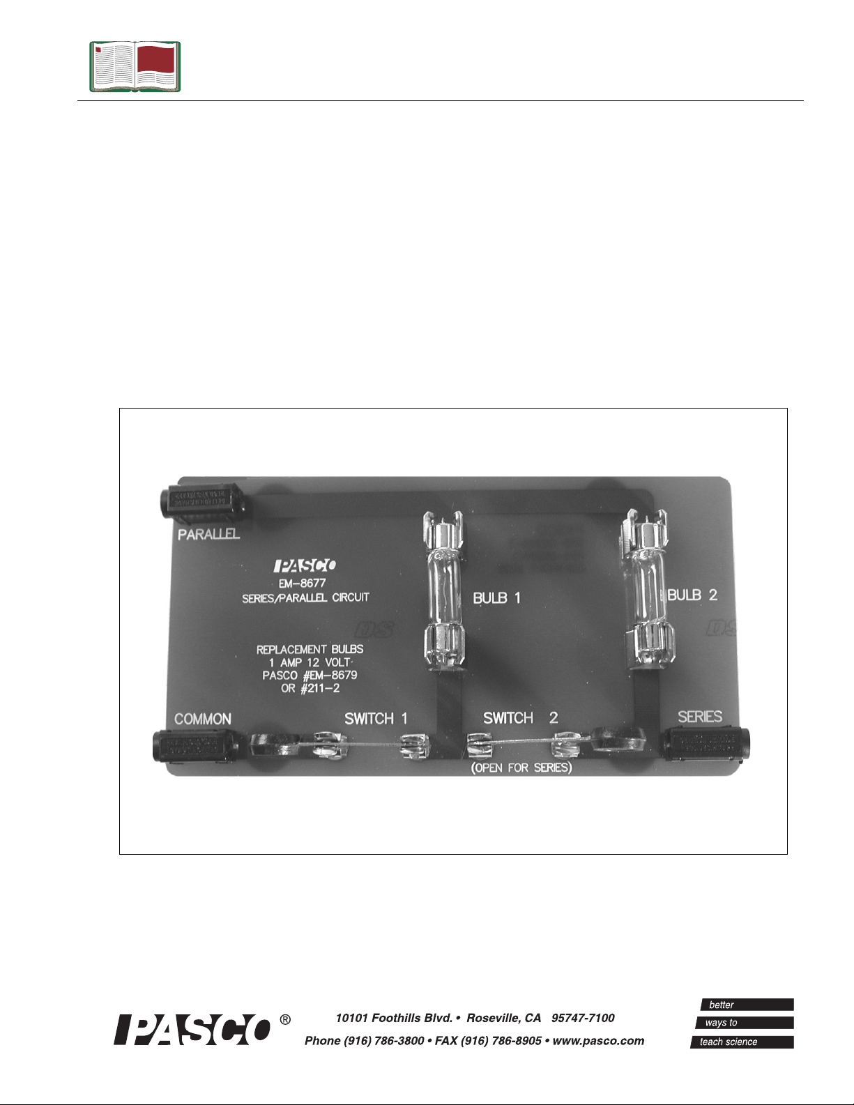
Introduction
The Series/Parallel Circuit is designed for standard electricity
experiments in the classroom. The board includes three ports (Series,
Parallel, and Common (Ground)), two switches, and two 12-volt light
bulbs. The board can be connected to a power source or generator,
such as PASCO’s Hand-Crank Generator (EM-8090).
Opening and Closing the Switches
In the Series/Parallel
Circuit, the switch is a
metal lever that can be
manually moved up and
down inside a metal clip
(See Figure 1). In an
electrical path, a closed
switch allows current
Figure 1: Open and closed switch
travel and an open
switch stops current
travel. To open a switch, move the handle up out of the clip. To close
the switch, use the handle to move the lever down into the metal clip.
(The lever must snap shut against the metal clip for the switch to be
closed.)
Closed
switch
metal clip
Open
switch
WARNING: The Series/
Parallel Circuit has
conductive properties.
Treat the circuit board as
you would other
conductors. Do not use
the circuit board around
water or place on other
conductive surfaces,
especially when the board
is connected to a power
source. Always connect
the ground lead to the
COMMON port and
inform your students of
standard electrical safety
precautions. PASCO
cannot be held responsible
for negligent safety
practices in the classroom.
Operation Procedure
1. Place the Series/Parallel Circuit on a non-conductive surface, such as a
wooden table. With the power source turned off and switches open,
connect the ground lead of the power source to the COMMON port.
WARNING: Do not use a power source greater than 12 volts
with the Series/Parallel Circuit. Exceeding the voltage is hazardous
and may destroy, melt, or burn components in the circuit board.
2. For current travel through the series circuit: Connect the positive
lead of the power source to the SERIES port. Close Switch 1 and
keep Switch 2 open. (See Figure 2 on page 6 for a schematic of the
electrical pathway.)
OR
4
®
Page 6

Model No. EM-8677 Series/Parallel Circuit
For current travel through the parallel circuit: Connect the
positive lead of the power source to the PARALLEL port. Close
Switch 1 to light Bulb 1 and/or close Switch 2 to light Bulb 2. (Switch
1 lights Bulb 1 and Switch 2 lights Bulb 2.) (See Figure 3 on page 6
for a schematic of the electrical pathway.)
Inserting and Replacing the Light Bulbs
The light bulbs come included in the package with the Series/Parallel
Circuit and insert into the metal clip holders mounted on the circuit
board. You will need to insert the the 12-volt light bulbs for the circuit
to operate properly. If you need replacement bulbs, order a package
using part no. EM-8679.
WARNING: Do not remove the bulb with the bulb lit or any
connected power sources turned on. To avoid the risk of shock, always
disconnect the red positive lead from the port on the circuit board and
turn off any connected power sources before removing the light bulb.
To remove a light bulb, use a screwdriver to gently lift up on one end
of the bulb, and lift the bulb out from the metal clips. Be careful not to
put force on the glass portion of the bulb.
®
5
Page 7

Series/Parallel Circuit Model No. EM-8677
Schematics/Electrical Paths
Series Circuit Path
PARALLEL
COMMON
Figure 2: Electrical pathway through a Series Circuit
Parallel Circuit Path
If Switch 2 is kept open,
current only travels
through Bulb 1.
SWITCH 1
PARALLEL
COMMON
BULB 1
SWITCH 2
SWITCH 1
BULB 2
SERIES
BULB 1
SWITCH 2
Switch 2 is
open.
BULB 2
SERIES
Figure 3: Electrical Pathway through a Parallel Circuit
6
®
Page 8

Model No. EM-8677 Series/Parallel Circuit
Appendix A: Technical Support
For assistance with the EM-8677 Series/Parallel Circuit Board or any other PASCO products,
contact PASCO as follows:
Address: PASCO scientific
10101 Foothills Blvd.
Roseville, CA 95747-7100
Phone: (916) 786-3800
FAX: (916) 786-3292
Web: www.pasco.com
Email: techsupp@pasco.com
Appendix B: Copyright and Warranty Information
Copyright Notice
The PASCO scientific 012-08345A Series/Parallel Circuit Manual is copyrighted and all
rights reserved. However, permission is granted to non-profit educational institutions for
reproduction of any part of the 012-08345A Series/Parallel Circuit Manual,providing the
reproductions are used only for their laboratories and are not sold for profit. Reproduction
under any other circumstances, without the written consent of PASCO scientific, is
prohibited.
Limited Warranty
PASCO scientific warrants the product to be free from defects in materials and workmanship
for a period of one year from the date of shipment to the customer. PASCO will repair or
replace, at its option, any part of the product which is deemed to be defective in material or
workmanship. The warranty does not cover damage to the product caused by abuse or
improper use. Determination of whether a product failure is the result of a manufacturing
defect or improper use by the customer shall be made solely by PASCO scientific.
Responsibility for the return of equipment for warranty repair belongs to the customer.
Equipment must be properly packed to prevent damage and shipped postage or freight
prepaid. (Damage caused by improper packing of the equipment for return shipment will not
be covered by the warranty.) Shipping costs for returning the equipment after repair will be
paid by PASCO scientific.
®
7
 Loading...