

Page 1
Instruction Sheet
for the PASCO
Model CI-6746
ECONOMY FORCE SENSOR
012-06906B
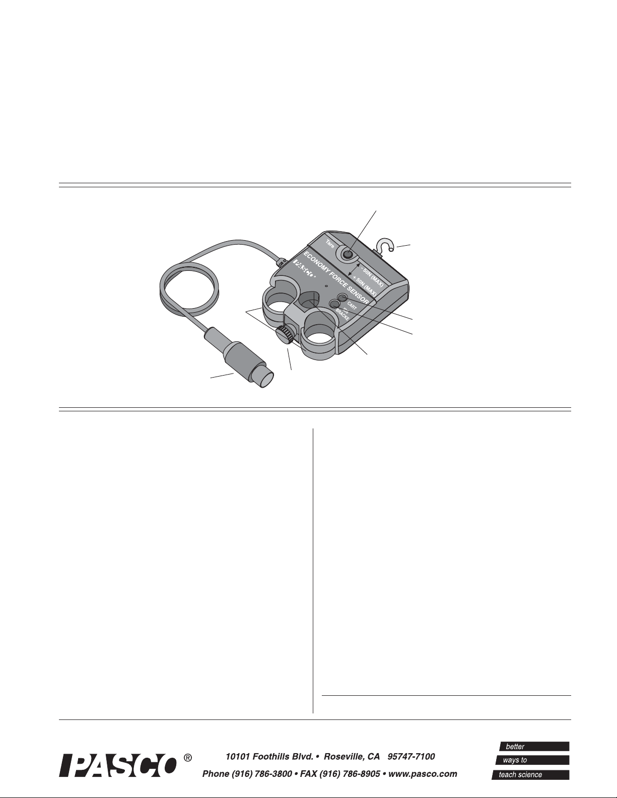
TARE button
detachable hook
finger
holds
Dynamics Cart mount
Accessory Bracket mount
8-pin DIN plug
Introduction
The PASCO CI-6746 Economy Force Sensor is
designed to be used with a PASCO
ScienceWorkshop Computer Interface. This
version of the force sensor has an output between
-8 volts and +8 volts and a range between -50
newtons and +50 newtons. In other words, it
produces -8 volts for -50 newtons, 0 volts for
“zero” force, and +8 volts for +50 newtons. (A
push is considered to be positive, and a pull is
considered to be negative.) The sensor has strain
gauges mounted on a specially designed “S-bend
beam”. The beam has built-in over-limit protection
so it will not be damaged if a force greater than 50
newtons is applied.
support rod mount
thumbscrew
The Force Sensor consists of the housing for the
beam and electronics, a cable with a 8 pin DIN
plug for connecting to the computer interface, and
a detachable hook. The housing has a thumbscrew
(for mounting on a support rod up to 1/2” diameter)
on the end opposite to the mount for the detachable
hook. The housing also has two finger holds.
The bottom of the housing has an indentation that
fits on the end of the accessory tray of a PASCO
Dynamics Cart. The top of the housing has a mount
(Cart) for attaching the sensor to a Dynamics Cart,
a mount (IDS Bracket) for the Accessory Bracket
with Bumpers (CI-6545) for attaching the sensor to
a Dynamics Track, and a tare button for zeroing the
sensor.
Page 2
Economy Force Sensor 012-06906B
®
Equipment
INCLUDED
• Economy Force Sensor (CI-6746)
• detachable hook
• accessory mounting thumbscrew
ADDITIONAL REQUIRED
• ScienceWorkshop Computer Interface
• Computer
ADDITIONAL RECOMMENDED
• Introductory Dynamics System (carts, track,
track accessories), such as PASCO Model
ME-9429A.
• Force Sensor Bracket and Collision Bumpers
(CI-6545)
Operation
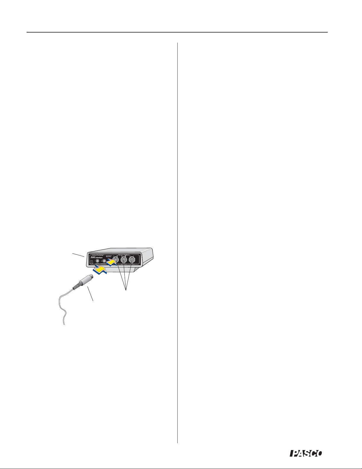
Connecting and Zeroing the Sensor
1. Connect the 8-pin DIN plug to an analog
channel on the computer interface.
ScienceWorkshop
500 Computer
Interface
Mounting the Sensor on a PASCO Dynamics Cart
The Economy Force Sensor has a built-in mount
that aligns with the threaded holes in the
accessory tray of a PASCO Dynamics Cart (such
as the ME-9430 Plunger Cart or ME-9454
Collision Cart ). A thumbscrew is provided to
secure the Force Sensor to the cart.
To mount the sensor:
1. Position the Economy Force Sensor on the tray of
the Dynamics Cart so the indentation on the
bottom of the Force Sensor is seated over the
end of the cart tray, and the mount for the cart
is directly over the threaded hole in the
accessory tray of the cart.
2. Insert the accessory mounting thumbscrew into
the cart mount hole and screw it into the
threaded hole in the accessory tray of the
Dynamics Cart.
Mounting on a Support Rod
The Economy Force Sensor has a hole and
thumbscrew at one end that allows you to mount
the sensor on a support rod from 3/8” to 1/2” diameter.
Mounting on the Accessory Bracket
analog channels
DIN plug
2. To “zero” the sensor, press and then release the
tare button. When the tare button is pressed, the
voltage from the sensor will be set to
approximately zero volts.
Note: You can also zero the sensor while a force
is applied to the sensor. For example, if you want
to measure the change in force during an
experiment, set up the experimental equipment as
needed, and tare the sensor at the beginning of the
experiment before taking data. The sensor can
maintain its “zeroed” condition for more than thirty
minutes.
To fasten the Economy Force Sensor to a Dynamics
Track, use the Accessory Bracket
(CI-6545):
1. Place the Force Sensor on the Accessory
Bracket so the IDS mount aligns with the hole
near the front of the bracket.
2. Insert the accessory mounting thumbscrew into
the IDS mount hole on the Economy Force
Sensor, and turn it clockwise until it is tight.
Mount the Accessory Bracket on the
T-slot on the side of the IDS Track. (See the
Accessory Bracket instruction sheet for more
information.)
2
Page 3

012-06906B Economy Force Sensor
Calibrating the Economy Force Sensor
The Economy Force Sensor is designed to produce
approximately zero volts when it is “zeroed”. A
change in force of one newton causes a change in
output voltage of 160 millivolts (0.160 V);
therefore, the sensor does not need to be
calibrated. Instead, the voltage can be converted
directly into force. For example, after the sensor is
“zeroed”, an output voltage of 0.160 volts equals a
force of one newton, a voltage of 1.60 volts equals
a force of 10 newtons, and so on. In the same way,
a voltage of -1.60 volts equals a force of -10
newtons (in other words, a pull of 10 newtons).
However, you can calibrate the sensor to learn
about the process of calibration. All calibrations
assume that the sensor produces an output
voltage that is linear with respect to the input
signal. Calibration is done by setting up two
calibration situations (such as “no force” and a
known force), measuring the input signal in each
situation in comparison to a known standard,
and entering the readings.
Suggested Experiments
Component of Force on an Inclined Plane
When a cart is at rest on an inclined plane, the
component of force acting on the cart that is
parallel to the plane is mgsinθ, where mg is the
weight of the cart and θ is the angle of the plane.
Use the sensor to measure the weight of a
Dynamics Cart. Mount the sensor at the high end
of the inclined Dynamics Track using an
Accessory Bracket (CI-6545), and connect it to a
Dynamics Cart on the track with a string. Measure
the angle of the track. Measure the tension in the
string, and compare this to the theoretical value
mgsinθ.
Force Sensor
Dynamics
Cart
mgsinθ
Accessory
Dynamics Track
mg
q
Bracket
mgcosθ
to computer
interface
General Calibration Procedure:
1. In your data acquisition software, open the
Force Sensor’s calibration dialog.
2. Place your Force Sensor in the lowest force
situation for which you are calibrating (such as,
no force).
3. Press the tare button to “zero” the Force Sensor.
4. In the calibration dialog, type the low value into
the LOW VALUE text box, and click the
READ button.
5. Apply a known force to the Force Sensor (for
example, hang a mass of known weight from
the detachable hook). This force should be
approximately that of the highest force you plan
to measure.
6. Type the value for the applied force in the
HIGH VALUE text box, and click the READ
button.
Newton’s Second Law: Pushing and Pulling a
Cart
When an object is accelerated by a net force, the
acceleration is directly proportional to the net force
and inversely proportional to the object’s mass.
Mount the Force Sensor onto a Dynamics Cart.
Use a Motion Sensor to measure the velocity and
acceleration of the cart. Zero the Force Sensor.
Hold the hook on the front of the Force Sensor,
and move the cart gently but irregularly back and
forth in front of the Motion Sensor. Use the
computer program to compare the measured force
to the measured velocity and acceleration.
Motion Sensor
Dyanmics Cart
Dynamics Track
Force Sensor
to computer interface
®
3
Page 4

Economy Force Sensor 012-06906B
®
Newton’s Second Law: Constant Force
What happens if the cart is pulled by a constant force?
Arrange the Motion Sensor, Force Sensor, and cart on
the track as in the previous suggested experiment. Set
up a Super Pulley (ME-9450), string, and hanging
mass so that the cart/Force Sensor will be pulled by
the string attached to the hanging mass. Use the
Motion Sensor to measure the velocity and
acceleration of the cart as it is pulled by the string. Use
the computer program to compare the measured force
to the measured velocity and acceleration.
Motion Sensor
to computer
interface
Force Sensor
Adjustable
End Stop
Super
Pulley
mass
Tension
What is the tension in the string in the previous
suggested experiment? Arrange the Force Sensor
and cart on the track as in the previous suggested
experiment. Set up a Super Pulley, string, and
hanging mass so that the cart/Force Sensor will be
pulled by the string attached to the hanging mass.
First, hold the cart at rest so the tension in the string
is “mg” (the hanging mass times the acceleration
due to gravity). Then, let go of the cart so it
accelerates toward the pulley. Use the program to
measure the amount of force in the string. The
tension should be constant, but less than “mg”.
Super
Pulley
mass
to computer
interface
Force Sensor
Adjustable
End Stop
Change the hanging mass and repeat the experiment.
Work-Energy Theorem: W =
∆∆
∆KE
∆∆
What happens to the kinetic energy of the cart as it
is pulled by a constant force? Arrange the Motion
Sensor, Force Sensor, and cart on the track as in
the previous suggested experiment. Set up a Super
Pulley (ME-9450), string, and hanging mass so
that the cart/Force Sensor will be pulled by the
string attached to the hanging mass. Use the
Motion Sensor to measure the change in position
and the velocity of the cart as it is pulled by the
string. Use the computer program to find the
integration under the curve of a force versus
distance graph. Use the program to calculate the
amount of kinetic energy gained by the cart.
Compare the calculated value of the work to the
calculated value of the final kinetic energy.
Motion Sensor
Force Sensor
Super
Pulley
Newton’s Second Law: Friction
Make observations when a force is applied to the cart/
Force Sensor and compare its acceleration when no
friction is present to the acceleration when friction is
added. You will need to add the Friction Cart
Accessory (ME-9457) to the Dynamics Cart. Arrange
the Motion Sensor, Force Sensor, and “friction” cart
on the track as in the previous suggested experiment.
Set up a Super Pulley, string, and hanging mass so the
cart/Force Sensor will be pulled by the string attached
to the hanging mass. Adjust the friction cart accessory
so the friction pad is not in contact with the track.
Accelerate the cart with a 50 gram mass. Use the
Motion Sensor to measure the velocity and
acceleration of the cart as it is pulled by the string.
Use the computer program to compare the measured
Motion Sensor
Force Sensor
Super
Pulley
to computer
interface
Adjustable
End Stop
mass
to computer
interface
Friction
Cart
Accessory
Adjustable
End Stop
mass
4
Page 5

012-06906B Economy Force Sensor
force to the measured velocity and acceleration. Adjust
the friction pad on the bottom of the cart until it is
rubbing against the track just enough to cause the cart
to move with a constant velocity as the 50 gram mass
falls. Use the Motion Sensor and the computer
program to analyze the force, velocity, and
acceleration. Finally, raise the friction pad so it rubs
the track slightly less than before, and repeat the
measurements.
Newton’s Third Law
“For every action, there is an opposite but equal
reaction.” Whenever one object exerts a force on a
second object, the second object exerts an equal
and opposite force on the first. Use two Force
Sensors. Set up the computer program so that a
push will be negative for one of the sensors. Hook
the two sensors together, and use the computer
program to measure the force from both Force
Sensors as you pull one Force Sensor with the
second Force Sensor.
Other Suggested Experiments
• Measure the force of a fan cart.
• Measure the centripetal force of a swinging
pendulum, and compare the force to the speed,
length, and mass of the pendulum.
• Measure the change in mass of liquid nitrogen
as it vaporizes versus the energy input to
vaporize the liquid nitrogen.
• Measure fluid drag forces on objects of various
shapes in a wind tunnel.
• Measure the net force acting on a pair of
harmonic oscillators.
• Study damped and undamped harmonic
motion using a mass and spring system.
Specifications
Output voltage: +8V for +50 newtons (pushing)
-8 V for -50 newtons (pulling)
Newton’s Third Law: Impulse/Collision
The impulse during a collision equals the change in
momentum during the collision:
F∆t = ∆mv
Mount the Force Sensor at one end of the track.
Arrange the cart and Motion Sensor so the Motion
Sensor can measure the motion of the cart as it is
pushed toward the Force Sensor, collides with it,
and rebounds. Use the computer program to
determine the impulse and the change in
momentum during the collision.
Motion Sensor
to computer interface
Force Sensor
Accessory
Bracket
Output noise: ±2 millivolts
Force slew rate: 30 newtons/millisecond
Bandwidth limit: 2 kilohertz
(internal low pass filter)
Output drive: 12 meters of cable without
instability.
Beam deflection: 0.28 mm
Note: This instruction sheet was written
assuming the user knows how to operate the
data acquisition software used with the
ScienceWorkshop Computer Interface. Please
see the appropriate printed manuals or online
help for specific instructions.
®
5
Page 6

Economy Force Sensor 012-06906B
®
Limited Warranty
PASCO scientific warrants the product to be free
from defects in materials and workmanship for a
period of one year from the date of shipment to the
customer. PASCO will repair or replace, at its
option, any part of the product which is deemed to
be defective in material or workmanship. The
warranty does not cover damage to the product
caused by abuse or improper use. Determination of
whether a product failure is the result of a
manufacturing defect or improper use by the
customer shall be made solely by PASCO
scientific. Responsibility for the return of
equipment for warranty repair belongs to the
customer. Equipment must be properly packed to
prevent damage and shipped postage or freight
prepaid. (Damage caused by improper packing of
the equipment for return shipment will not be
covered by the warranty.) Shipping costs for
returning the equipment after repair will be paid by
PASCO scientific.
Address: PASCO scientific
10101 Foothills Blvd.
Roseville, CA 95747-7100
Phone: (916) 786-3800
FAX: (916) 786-8905
e-mail: techsupp@pasco.com
web: www.pasco.com
Contacting Technical Support
Before you call the PASCO Technical Support
staff, it would be helpful to prepare the following
information:
➤ If your problem is computer/software related,
note:
- Title and revision date of software;
- Type of computer (make, model, speed);
- Type of external cables/peripherals.
➤ If your problem is with the PASCO apparatus,
note:
- Title and model number (usually listed on the
label);
- Approximate age of apparatus;
- A detailed description of the problem/sequence
of events (in case you can’t call PASCO right
away, you won’t lose valuable data);
- If possible, have the apparatus within reach
when calling to facilitate description of
individual parts.
➤ If your problem relates to the instruction
manual, note:
- Part number and revision (listed by month and
year on the front cover);
- Have the manual at hand to discuss your
questions.
Feedback
If you have any comments about the product or
manual, please let us know. If you have any
suggestions on alternate experiments or find a
problem in the manual, please tell us. PASCO
appreciates any customer feedback. Your input
helps us evaluate and improve our product.
To Reach PASCO
For technical support, call us at 1-800-772-8700
(toll-free within the U.S.) or (916) 786-3800.
fax: (916) 786-3292
e-mail: techsupp@pasco.com
web: www.pasco.com
6
 Loading...