

Page 1
®
Quick Start
Included Equipment Part Number
Motion Sensor II CI-6742A
Additional Equipment Required
ScienceWorkshop-compatible
Interface
UI-5000, CI-7650,
CI-6400, or similar
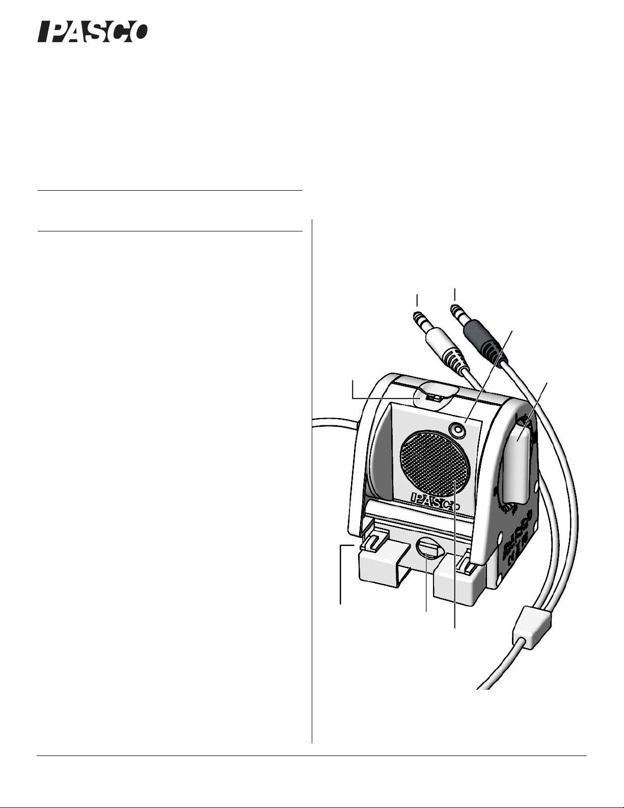
Yellow Plug
(left)
Black Plug
(right)
Range
Switch
Ultrasonic
Transducer
Rotating
Head
Clips for
mounting
on track
Hole for
mounting
on rod
Target
Indicator
Motion Sensor II
Motion Sensor II
CI-6742A
CI-6742A
Theory of operation and specifications are listed at the end of the
instruction sheet.
Note: Essential PASCO Capstone tasks are described briefly in this
instruction sheet. For more instructions on using Capstone, see the User’s
Guide or the online help
.
Instruction Sheet
012-09624B
1. Connect the Motion Sensor II to your ScienceWork-
shop-compatible interface (such as the 850 Universal Inter-
face or ScienceWorkshop 750 USB Interface).
2. If you are using a computer, connect the PASCO interface to
it, turn the interface on, and start the data acquisition software (such as PASCO Capstone).
3. Place an object in front of the sensor at least 15 cm away.
4. Click “Record” or press “Start” to begin recording data.
5. Move the object in a straight line directly away from or
toward the sensor.
Introduction
The Motion Sensor II works with a ScienceWorkshop-compatible
interface and PASCO data acquisition software (such as PASCO
Capstone) to measure and record motion data. It produces a series
of ultrasonic pulses and detects the sound reflecting back from an
object in front of it. The interface measures the times between
outgoing pulses and returning echoes. From these measurements,
the data acquisition software determines the position, velocity,
and acceleration of the object.
This instruction sheet includes procedures for setting up the hardware and software, collecting data, changing the sample rate,
mounting the sensor on equipment, and troubleshooting.
800-772-8700 www.pasco.com
Page 2
®
Motion Sensor II CI-6742A
Yellow Plug
Black Plug
DIGITAL
INPUT
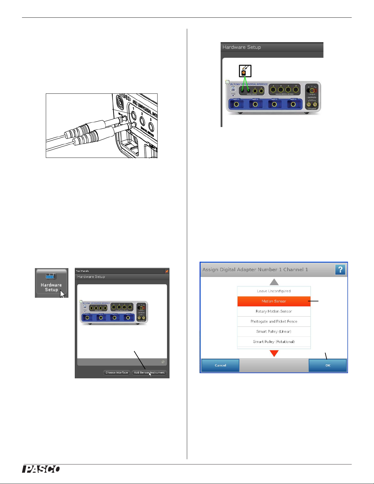
Click “Add
Sensor/Instrument”
Hardware
Setup
icon
Motion Sensor Icon
850 Interface Icon
1) Press
“Motion
Sensor”
2) Press
“OK”
Set-up
To Connect to a PASCO Interface
Connect the Motion Sensor's yellow plug to DIGITAL INPUT 1
(or Digital Channel 1) of your ScienceWorkshop-compatible
interface. Connect the black plug to DIGITAL INPUT 2 (or Digital Channel 2).
NOTE: If you are using a PASPORT-only interface (such as the
SPARK Science Learning System), use a PS-2159 Digital
Adapter to connect the Motion Sensor to the interface. Put the
yellow plug into Input Port 1, and the black plug into Input Port
2. Plug the Digital Adapter into a port on the PASPORT-only
interface.
PASCO Capstone Setup
6. Confirm that the “Hardware Setup” panel shows the icon of
the Motion Sensor and the icon of the interface.
7. Double-click the Graph icon in the Displays palette (or
other display icon) to create a data display.
8. In a Graph display, click the “Select Measurement” menu
button on the vertical axis and select position, velocity, or
acceleration. Click “OK”.
SPARK Science Learning System (SLS) Setup
1. Turn on the interface. Connect the Motion Sensor’s plugs to
the input ports on a PS-2159 Digital Adapter, and plug the
adapter into the interface.
1. Turn on the interface and launch the PASCO data acquisition
software, such as PASCO Capstone..
2. In PASCO Capstone, click the “Hardware Setup” icon in
the Tools palette to open the “Hardware Setup” panel.
3. In the “Hardware Setup” panel, click “Add Sensor/Instrument” to open the “Add Sensor or Instrument” window.
4. In the “Add Sensor or Instrument window, click the “Sensor
or Instrument Type” menu and select “ScienceWorkshop
Digital Sensors” from the list.
5. Select “Motion Sensor II” in the list and then click “OK”.
2. The SPARKvue program recognizes that the Digital Adapter
is connected to the interface, and shows a screen with a list
of digital sensors. Press “Motion Sensor” and then press
“OK”.
2
Page 3

®
Motion Sensor II CI-6742A
1) Select a
parameter.
2) Press
Show.
Recording
Mode menu
Sample Rate setting
3. Press “OK” in the Edit Sensor Properties screen, and then
press to select “Position”, “Velocity”, or “Acceleration” in
the next screen.
4. Press “Show” to create a Graph screen. The Graph shows the
parameter you selected on the vertical axis, and time on the
horizontal axis.
To Aim the Motion Sensor at an Object
Data Collection
To Record Data
1. In PASCO Capstone, click Record. In SPARKvue, press
Start.
• The Motion Sensor starts clicking. If a target is in range, the
target indicator flashes with each click. The data acquisition
software starts collecting and displaying data.
2. Click Stop to stop data collection.
To Display Data without Recording
PASCO Capstone
Click the Recording Mode menu and select
Fast Monitor Mode. The Record icon changes
to a Monitor icon. Click Monitor to display
live data without recording it.
Sensor Configuration
1. Set the range switch to short range ( ) or long range ( )
setting.
• Select for measuring a cart on a track.
• Select for measuring most other objects.
2. Arrange the Motion Sensor and object so that the Motion
Sensor's transducer faces the object.
• The object should be at least 15 cm from the transducer.
• If the object will move, it should move directly toward
or away from the Motion Sensor.
• Aim the motion sensor slightly up to avoid detecting the
tabletop.
3. Remove objects that may interfere with the measurement.
These include objects between the sensor and target object,
either directly in front of the sensor or to the sides.
To Change the Sample Rate
PASCO Capstone
Click the up or down button next
to the Sample Rate setting.
SPARKvue
In the Graph display screen, press the Sampling Options icon.
Select the Sampling Mode, Sample Rate, and Sample Rate
Unit in the Sampling Options screen, and then press OK.
The normal range of sampling rates is between 1 Hz and 50 Hz.
At the default rate, the Motion Sensor can measure distance up to
8 m. The maximum distance decreases with increasing sample
rate. At very high sample rates (between 50 Hz and 250 Hz), the
maximum distance is less than 2 m.
Equipment Mounting
Mount the Motion Sensor as illustrated on a vertical rod (a) or a
horizontal rod (b).
Integrated clips allow it to be attached to the end of a dynamics
track (c).
A threaded hole in the bottom of the unit (d) is provided for
attachment to the PS-2546 Magnetic Bracket (e), the ME-6743
3
Page 4

®
Motion Sensor II CI-6742A
(a)
(b)
(c)
(d)
(e)
(f)
(g)
(h)
Cart Adapter (f), and other 1/4-20 threaded mounting devices
such as a camera tripod.
To protect the Motion Sensor from being hit by an object, use a
device such as the SE-7256 Motion Sensor Guard (g) or
ME-9806 bracket with a rubber band (h). The Motion Sensor can
“see through” a wire screen or rubber band placed close to the
transducer.
Troubleshooting
If the Motion Sensor fails to perform satisfactorily, try these
steps:
• Ensure that the target object is no closer than 15 cm.
• Switch the range switch to the other setting.
• Adjust the aim left, right, up, or down. In some cases the
Motion Sensor works best when it is aimed slightly to the
side or above the target in order to exclude interfering
objects.
• Improve the target by adding a larger or harder surface to
reflect ultrasound. A small object can be a better reflector
than large object if it has a harder surface.
• Remove interfering objects near the target object or sensor.
• Increase or decrease the sample rate.
Theory of Operation
The Motion Sensor uses an electrostatic transducer as both a
speaker and a microphone. When triggered by the interface, the
transducer transmits a burst of 16 ultrasonic pluses with a frequency of about 49 kHz. This burst of pulses can be heard as a
single click. The ultrasonic pulses reflect off an object and return
to the sensor. The tar get indicator on the sensor flashes when
transducer detects an echo.
Sound intensity decreases with distance; to compensate, the sensor increases the gain of the receiver amplifier as it waits for the
echo. The increased gain allows the sensor to detect an object up
to 8 m away. The lower gain at the beginning of the cycle reduces
the circuit's sensitivity to echoes from false targets.
The interface measures the time between trigger rising edge and
the echo rising edge. The data acquisition software uses this time
and the speed of sound to calculate the distance to the object. To
determine velocity, the software uses consecutive position measurements to calculate the rate of change of position. Similarly, it
determines acceleration using consecutive velocity measurements.
4
Page 5

®
Motion Sensor II CI-6742A
Specifications
Minimum Range 15 cm
Maximum Range 8 m
Transducer Rotation 360°
Range Settings Short Range: for distance measurement up
Mounting Options On rod up to 12.7 mm diameter
Connector Dual stereo phone plug for
to 2 m with improved rejection of false target
signals and air-track noise
Long Range: for distance measurement up
to 8 m
Directly to PASCO dynamics tracks
On table top
ScienceWorkshop-compatible interfaces
Technical Support
For assistance with any PASCO product, contact PASCO at:
Address:
Phone:
Web: www.pasco.com
Email: support@pasco.com
PASCO scientific
10101 Foothills Blvd.
Roseville, CA 95747-7100
916-786-3800 (worldwide)
800-772-8700 (U.S.)
The European Union WEEE (Waste Electronic and Electrical Equipment) symbol (to
the right) and on the product or its packaging indicates that this product must not be
disposed of in a standard waste container.
Limited Warranty For a description of the product warranty, see the
PASCO catalog.
Copyright The PASCO scientific 012-09624B Motion Sensor II Instruc-
tion Sheet is copyrighted with all rights reserved. Permission is granted to
non-profit educational institutions for reproduction of any part of this manual, providing the reproductions are used only in their laboratories and
classrooms, and are not sold for profit. Reproduction under any other circumstances, without the written consent of PASCO scientific, is prohibited.
Trademarks PASCO, PASCO scientific, PASCO Capstone, SPARK SLS,
and SPARKvue are trademarks or registered trademarks of PASCO scientific, in the United States and/or in other countries. All other brands, products, or service names are or may be trademarks or service marks of, and
are used to identify, products or services of, their respective owners. For
more information visit www.pasco.com/legal.
Product End of Life Disposal Instructions:
This electronic product is subject to disposal and recycling regulations that vary by country and region. It is your responsibility to
recycle your electronic equipment per your local environmental
laws and regulations to ensure that it will be recycled in a manner
that protects human health and the environment. To find out
where you can drop off your waste equipment for recycling,
please contact your local waste recycle/disposal service, or the
place where you purchased the product.
5
 Loading...