

Page 1
Instruction Sheet
for the PASCO
Model CI-6740
012-08627A
High Current Sensor
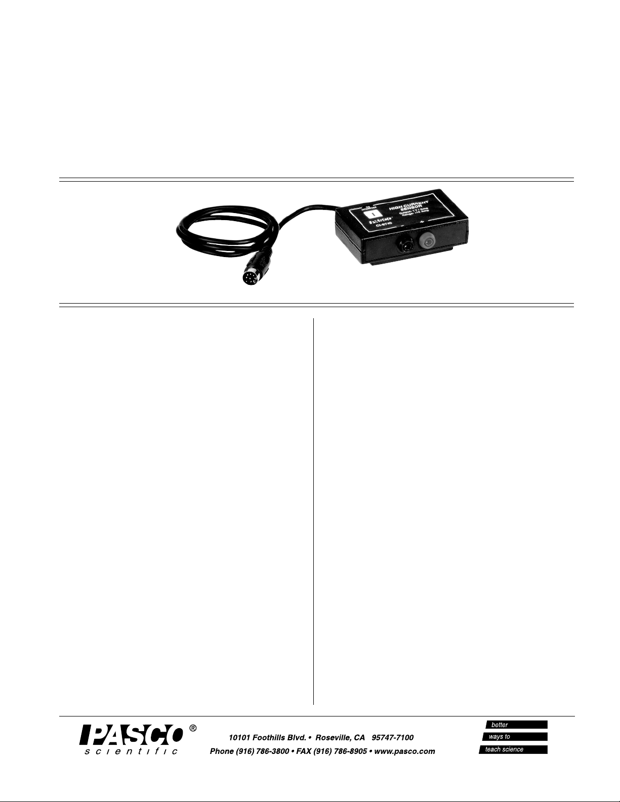
Introduction
The PASCO CI-6740 High Current Sensor measures
both AC or DC current between 0 and 10 amperes.
The High Current Sensor is ideal for circuits in which
the current exceeds 1 ampere. Instead of a sensing
resistor, the High Current sensor uses a Hall-Effect
chip, which has no internal resistance and therefore
generally eliminates the need to account for sensor
resistance. The sensor includes a 10-amp fuse, which
is replaceable.
With a set of banana plugs or lead inputs, the High
Current Sensor connects directly to a power supply or
to any PASCO circuit board.
Equipment included:
• High Current Sensor (CI-6740)
Additional equipment required:
• ScienceWorkshop® computer interface
• DataStudio software, version 1.8.5 or later
• Banana plugs (1 or more sets) (For one set of
banana plugs, use part no. 517-007 and 517-008.
For a 5-pack of leads, use SE-9750 and SE-9751.)
Specifications:
• Maximum current input: 10 Amps
• Maximum voltage input: 30 Volts
• Resolution: 5 milliamps
• Frequency response: DC to 16 Khz
• Fuse: 10 Amps, fast-acting (replaceable)
• Insertion resistance: 0.03 ohms (maximum)
Typical Applications:
• Determine the current output from PASCO’s
Hand Crank Generator or a power supply
• Measure the current through a PASCO coil
Page 2
CI-6740 012-08627A
Safety Precautions
SAFETY WARNING: When operating the High
Current Sensor, follow standard electrical safety
precautions in your classroom. To avoid the risk of
shock, do not use the High Current Sensor in or near
water, liquids, or chemicals. Also, keep water and
other liquids away from any devices connected to the
High Current Sensor, such as a power supply or other
electrical devices. When using a power supply,
connect the power supply and any other connected
equipment to a ground, such as a three-pronged wall
outlet.
Equipment Setup Options
CAUTION: To avoid magnetic interference,
which might reduce the accuracy of the sensor, keep the
High Current Sensor away from magnets. To avoid
overloading the circuit inside the sensor, do not exceed a
current of 10 amps.
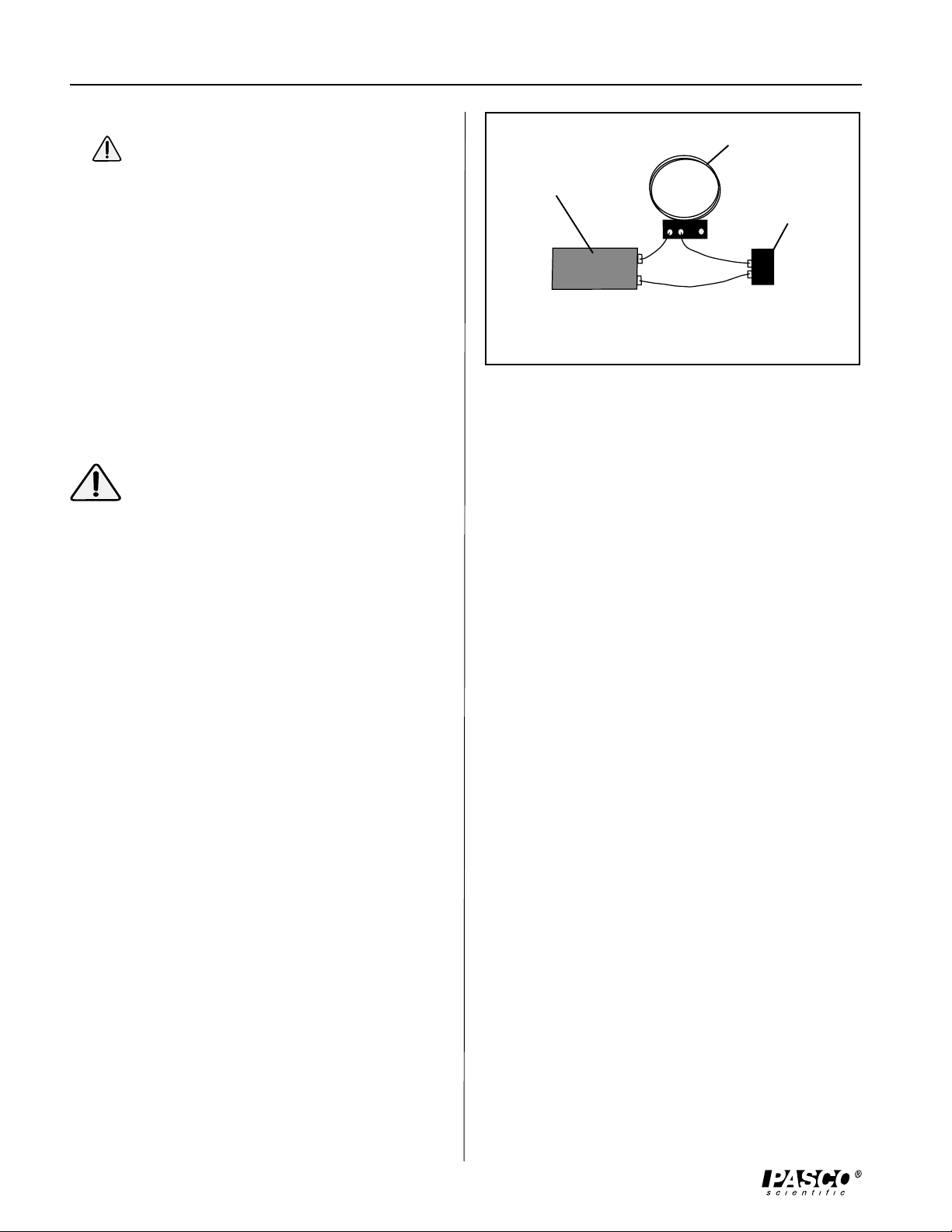
Coil
Power Supply
Sensor
Figure 1: Series connection between a
power supply, Field Coil, and High Current
Sensor
4. (Optional): For induction studies, use a PASCO
Detector Coil to monitor current from the Field Coil.
5. Follow the steps under “Software Setup and Data
Collection.”
b) Connecting the High Current Sensor to a PASCO
Hand-Crank Generator (EM-8090)
a) Connecting the High Current Sensor to a PASCO
Coil
The High Current Sensor can be used with any of
the following PASCO coils (EM-6711, EM-6712,
EM-6713, and EM-6714). The High Current Sensor
must be connected in series with the circuit to be
measured.
1. Connect banana plugs to create a series circuit
between the power supply, Field Coil, and High
Current Sensor (Figure 1). A sample series circuit
connection is as follows: a) from the positive port on
the power supply to the negative port on the Field
Coil, and b) from the positive port on the Field Coil
to the negative port on the High Current Sensor, and
c) from the positive port on the High Current Sensor
to the negative port on the power supply.
2. Insert the DIN plug connector into an analog
channel on a ScienceWorkshop interface.
1. Using banana plug connectors or other leads, connect
the Hand-Crank Generator in series with a High
Current Sensor and a circuit board.
2. Insert the DIN plug connector into an analog
channel on a ScienceWorkshop interface.
3. Follow the steps under “Software Setup and Data
Collection.”
3. Turn on the power supply.
2
Page 3

012-08627A CI-6740
Software Setup and Data Collection
1. Open DataStudio and double click “Create
Experiment.”
2. In the Sensors list of the Experiment Setup
window, drag the High Current Sensor icon to a
analog channel on the picture of the interface (the
same channel in which your sensor is connected).
3. Double click on the sensor icon to open the Current
Sensor Properties dialog. In the Current
Properties dialog, you can accept or change the
sample rate or optionally calibrate the sensor. Click
OK.
4. To collect data, click the Start button on the main
toolbar. To stop data collection, click the Stop
button.
Calibrating the High Current Sensor
Suggested Experiment
Activity: Monitoring the Current from a HandCrank Generator
Equipment required: High Current Sensor (CI-6740),
Hand-Crank Generator (EM-8090), circuit board, such
as the Series/Parallel Circuit Board (EM-8677)
1. Using banana plug connectors or other leads, connect
the Hand-Crank Generator in series with a High
Current Sensor and a circuit board.
2. Plug the DIN connector on the High Current Sensor
into an analog channel on a ScienceWorkshop
interface.
3. In DataStudio’s Experiment Setup window, drag the
High Current Sensor icon to the analog channel on
the picture of the interface (the same channel in
which you have your sensor connected).
Calibrating the High Current Sensor is not required. If
you wish to calibrate the sensor for better accuracy,
you may do so with DataStudio software. You will
need both a known low and high current source. An
open circuit (zero amps) is an acceptable “low”
current.
Procedure:
1. In the Experiment Setup window, double click on
the Current Sensor icon.
2. Click on the Calibration tab.
3. Disconnect the sensor from the external circuit.
4. Enter zero for the Low Point Value and click the
Take Reading button.
5. When the current reading stabilizes at the known
current, click the Take Reading button.
4. From the Data list, drag the Current icon to a
display.
5. Click the Start button to begin collecting data.
Crank the Hand-Crank Generator and monitor the
current in DataStudio.
6. To end data collection, click the Stop button.
6. Connect the High Current Sensor to a known high
current source. Enter the current into the High Point
Value and click the Take Reading button.
7. Click the OK button to save the calibration.
3
Page 4

CI-6740 012-08627A
Sample Data
Figure 2: Current Recorded from a Hand
Crank Generator (EM-8090)
Replacing the Fuse in the High Current Sensor
The High Current Sensor requires a 10 amp “mini-blade”
fuse. If the fuse burns out, replace it with a fuse with a
10-amp rating. Replacing a fuse with a higher rating may
cause a current overload.
To replace the fuse, unscrew the screws on the back side of
the High Current Sensor box. Remove the back casing and
install the new fuse (See Figure 3).
fuse
Technical Support
Address: PASCO scientific
10101 Foothills Blvd.
Roseville, CA 95747-7100
Phone: (916) 786-3800
FAX: (916) 786-8905
E-mail: techsupp@pasco.com
Web site: www.pasco.com
Limited Warranty
For a description of the product warranty, see the
PASCO catalog.
Copyright Information
The PASCO 012-08627A High Current Sensor
Manual is copyrighted and all rights reserved.
However, permission is granted to non-profit
educational institutions for reproduction of any part of
the 012-08627A High Current Sensor Manual,
providing the reproductions are used only for their
laboratories and are not used for profit. Reproduction
under any other circumstances, without the written
consent of PASCO scientific, is prohibited.
Figure 3: Replacing the fuse
Note: This instruction sheet was written assuming
that the user is familiar with DataStudio. Users can
gain familiarity by working through the tutorials
provided from DataStudio’s Online Help.
The exclamation point within an
equilateral triangle is intended to alert the
user of important operating and safety
instructions that will help prevent
damage to the equipment or injury to the
user.
4
 Loading...