

Page 1
Instruction Sheet
for the PASCO
Model CI-6685
BNC Adapter
012-07157A
6/99
$1.00
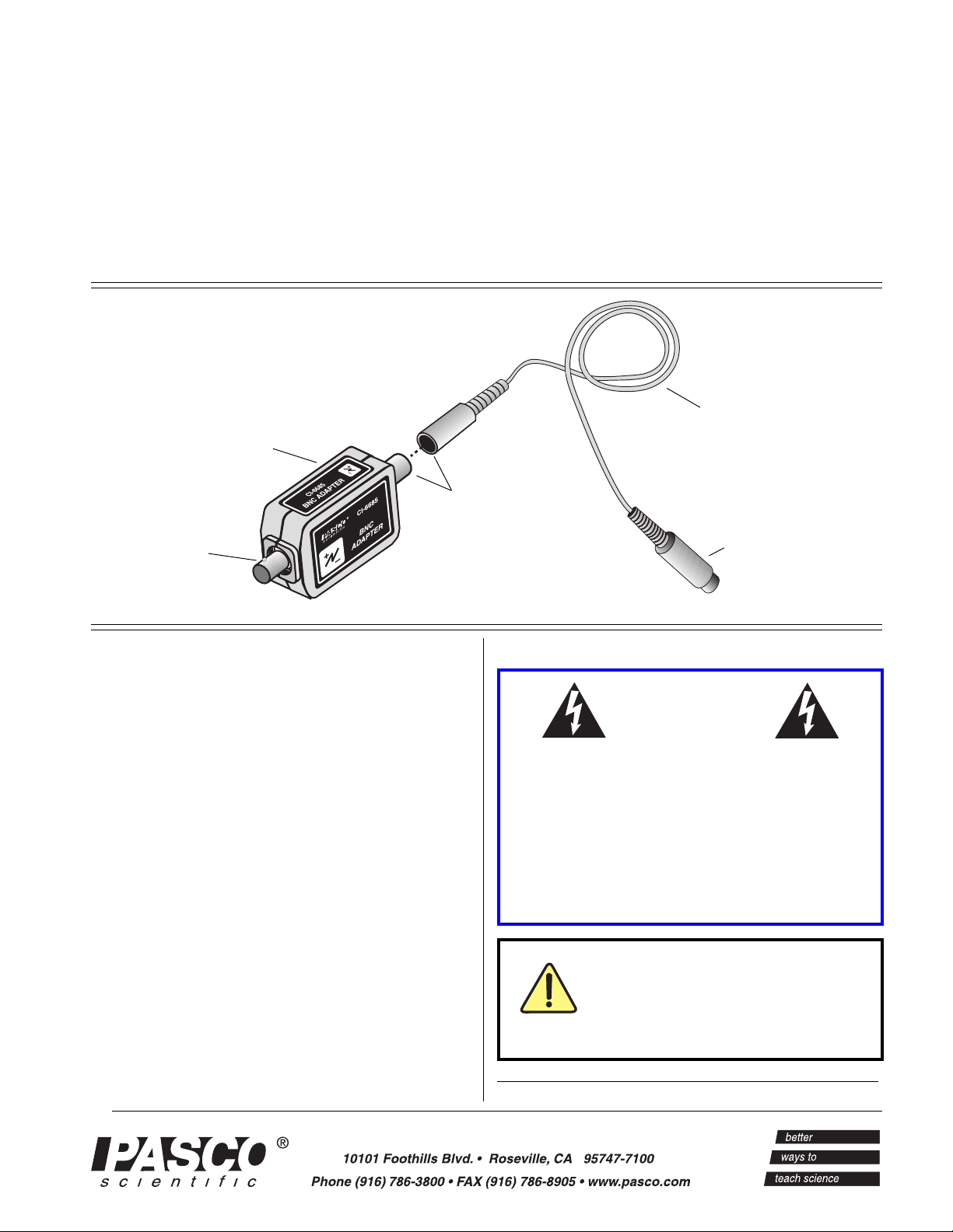
BNC ADAPTER
extension cable
5-pin DIN connector
BNC connector
Introduction
The PASCO CI-6685 BNC Adapter adapts a BNC
connector to a 5-pin DIN connector. The BNC
Adapter allows sensors with BNC connectors to be
used with a PASCO ScienceWorkshop
interface to measure voltages ranging from -10 volts
to +10 volts.
®
computer
Equipment
INCLUDED
• BNC adapter (CI-6685)
• 2-meter cable with 5-pin DIN connectors
ADDITIONAL REQUIRED
• Any PASCO Science Workshop computer
interface (300, 500, or 700 series for Macintosh or
Windows) or the 6500 series interface for DOS
5-pin DIN connector
W ar ning
Application of electrical voltage in excess of the
values listed in the product specification section
may damage this product, create a safety hazard,
and may endanger the oper-ator. This device
does not use or produce voltages that exceed
42.4 VAC peak, 30 VAC RMS, or 60 VDC.
Connecting a probe’s ground lead
to any potential other than ground
could cause damage to the circuit
being measured, the BNC Adapter,
or the ScienceWorkshop Interface.
© 1999 PASCO scientific
Page 2
BNC Adapter 012-07157A
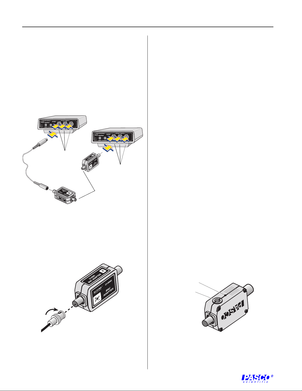
Setup Procedure
1. Connect the BNC Adapter to any analog channel
on the ScienceWorkshop computer interface box
with the interface cable (Figure 1a),
or
Insert the DIN plug of the BNC Adapter into the
jack of any analog channel on the
ScienceWorkshop computer interface box (Figure
1b).
Plug into
any analog
channel.
Connect usersupplied probe.
Plug into
any analog
channel.
3. Set up the BNC adapter in the data acquisition
software program (ScienceWorkshop or
DataStudio) as if it were a Voltage Sensor:
Associate the Voltage Sensor icon with the picture
of the analog channel that the BNC Adapter is
plugged into.
About the BNC Adapter
The BNC Adapter allows probes equipped with BNC
connectors (including those sold by Pomona
Electronics) to be used with ScienceWorkshop
interfaces.
The CI-6685 BNC Adapter adapts a probe with a male
BNC connector to a 5-pin DIN style input. The
adapter allows only single-ended measurements (i.e.,
measurements that are ground referenced).
Caution: Connecting a probe’s ground lead to any
potential other than ground could cause damage to the
circuit being measured, the BNC Adapter, or the
ScienceWorkshop Interface.
Figure 1
Connecting the BNC Adapter to the
Workshop
computer interface
Science-
2. Connect the BNC connector of the probe to the
BNC Adapter as shown in Figure 2.
Figure 2
Connecting the user-supplied probe with a BNC
connector to the BNC Adapter
Mounting on an Experimental Apparatus
1. Use the 1/4–20 threaded screw connector located
on the bottom of the sensor box to secure the BNC
Adapter to an experimental apparatus (Figure 3).
The alignment hole fits over an alignment pin
included on some PASCO apparatuses.
alignment hole
1/4–20 threaded
screw connector
Figure 3
Connections for mounting on some PASCO
experimental apparatuses
2
Page 3

012-07157A BNC Adapter
Tips on Using Oscilloscope Probes
Oscilloscope probes are convenient to use for many
measurements. However, it is important to determine
which of the two common types the probe is: X1
(times one) or X10 (times 10). X1 probes are
sometimes used with low level signals where signal
attenuation is undesirable. X10 probes are useful for
making measurements where you do not want the
probe to load the circuit significantly.
When used with a ScienceWorkshop Interface, a X10
probe will form a voltage divider with the interface.
Depending on the interface in use, this division will
vary.
Table 1 shows the input resistance of the various
PASCO Computer Interfaces. Note that the resistance
can also vary with the channel in use.
T able 1
Input resistance of the
interface analog channels
ScienceWorkshop
computer
DIN Connector Specifications
1: analog output (+),
-10 to +10 V
2: analog output (-),
signal ground
3: (no connection)
4: (no connection)
5: power ground
(internally connected
to signal ground)
1
4
3
5
2
Specifications
maximum input voltage: ±10 V
input resistance: interface dependent (see Table 1)
Note: This instruction sheet was written
assuming that the user is familiar with
ScienceWorkshop or DataStudio. Users can
gain familiarity by working through the
tutorials provided with ScienceWorkshop or
from DataStudio’s Online Help.
Interface Input Resistance (ohms)
Channel A Channel B Channel C
300/500 2M 200K 200K
700 2M 2M 2M
750 1M 1M 1M
A straightforward use of a X10 probe would be to use
it with a ScienceWorkshop 750 Interface with the
analog channel set for 10X gain. Use of a X10 probe
with any other interface will require that the raw
reading be modified within the data acquisition
software to obtain the correct result.
Given the potential for errors, it is normally best to use
a X1 probe.
The exclamation point within an
equilateral triangle is intended to alert
the user of the presence of important
operating and maintenance (servicing)
instructions in the literature
accompanying the device.
3
Page 4

BNC Adapter 012-07157A
Copyright, Warranty, and Equipment Return
Please—Feel free to duplicate this instruction sheet
subject to the copyright restrictions below.
Copyright Notice
The PASCO scientific 012-07157A BNC Adapter
instruction sheet is copyrighted and all rights reserved.
However, permission is granted to non-profit
educational institutions for reproduction of any part of
the manual providing the reproductions are used only
for their laboratories and are not sold for profit.
Reproduction under any other circumstances, without
the written consent of PASCO scientific, is prohibited.
Limited Warranty
PASCO scientific warrants the product to be free from
defects in materials and workmanship for a period of
one year from the date of shipment to the customer.
PASCO will repair or replace at its option any part of
the product which is deemed to be defective in
material or workmanship. The warranty does not
cover damage to the product caused by abuse or
improper use. Determination of whether a product
failure is the result of a manufacturing defect or
improper use by the customer shall be made solely by
PASCO scientific. Responsibility for the return of
equipment for warranty repair belongs to the
customer. Equipment must be properly packed to
prevent damage and shipped postage or freight
prepaid. (Damage caused by improper packing of the
equipment for return shipment will not be covered by
the warranty.) Shipping costs for returning the
equipment after repair will be paid by PASCO
scientific.
Credits
Author: Fred E. Luffman
Editor: Sunny Bishop
Equipment Return
Should the product have to be returned to PASCO
scientific for any reason, notify PASCO scientific by
letter, phone, or fax BEFORE returning the product.
Upon notification, the return authorization and
shipping instructions will be promptly issued.
ä NOTE: NO EQUIPMENT WILL BE
ACCEPTED FOR RETURN WITHOUT AN
AUTHORIZATION FROM PASCO.
When returning equipment for repair, the units must
be packed properly. Carriers will not accept
responsibility for damage caused by improper
packing. To be certain the unit will not be damaged in
shipment, observe the following rules:
À
The packing carton must be strong enough for the
item shipped.
Á
Make certain there are at least two inches of packing
material between any point on the apparatus and the
inside walls of the carton.
Â
Make certain that the packing material cannot shift in
the box or become compressed, allowing the
instrument come in contact with the packing carton.
Address: PASCO scientific
10101 Foothills Blvd.
Roseville, CA 95747-7100
Phone: (916) 786-3800
FAX: (916) 786-3292
email: techsupp@pasco.com
web:www.pasco.com
4
 Loading...