

Page 1
Instruction Sheet for the
PASCO
Model CI-6628
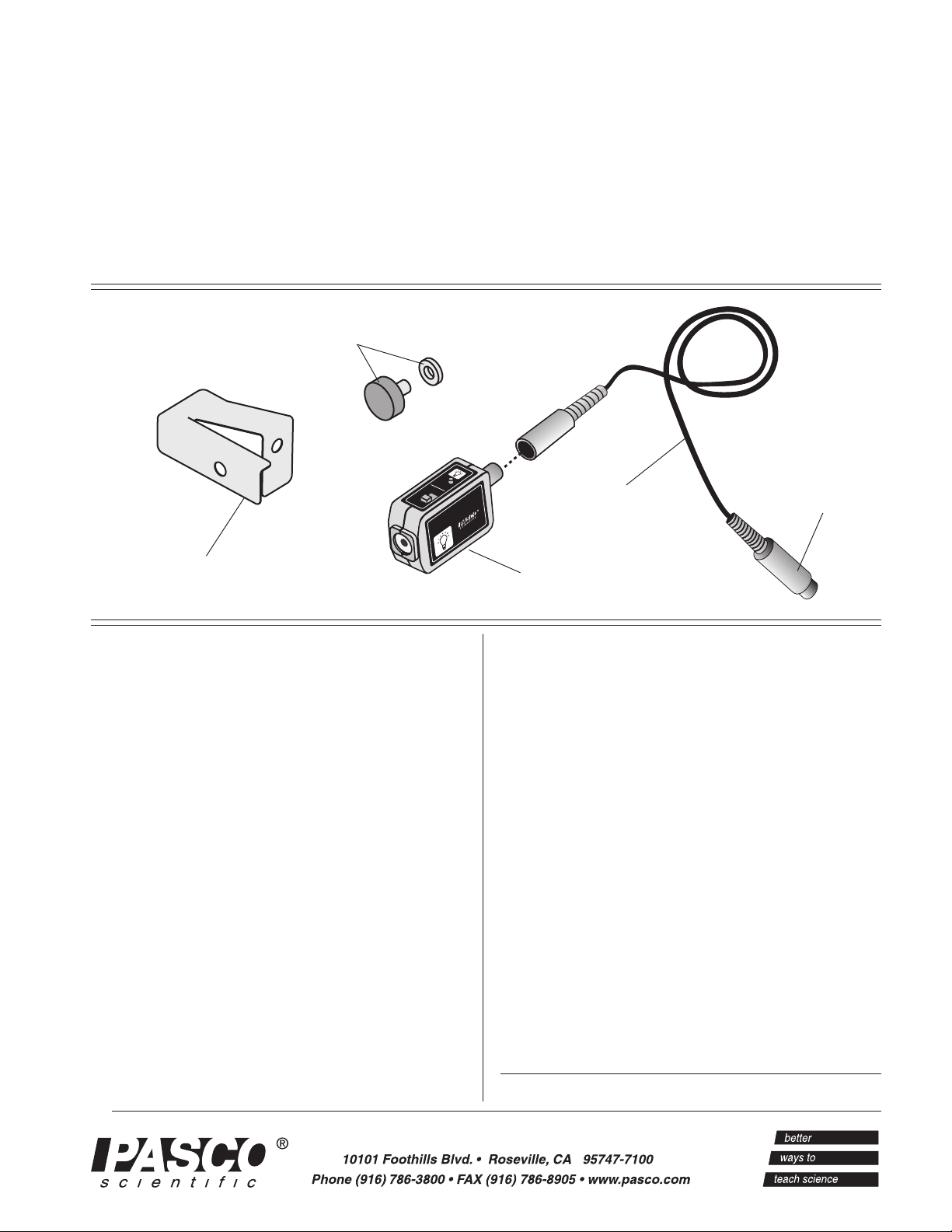
INFRARED SENSOR
mounting
thumbscrew
with washer
TARE
GAIN
1
10
100
INFRARED SENSOR
CI-6628
cable with DIN
connectors
012-06915B
to computer
interface
shutter bracket
Introduction
The sensing element used in the PASCO CI-6628
Infrared Sensor is a thermopile. Thermopile
detectors are voltage-generating devices that can
be thought of as a miniature array of
thermocouples. The thermopile is a high output,
thin film, silicon based device which has 48
thermopile junctions. The active or ‘Hot’ junctions
are blackened to efficiently absorb radiation. The
reference or ‘Cold’ junctions are maintained at the
ambient temperature of the detector
The blackening material used on the ‘Hot’
junctions is capable of absorbing radiant energy
from ultra violet to the far infrared. In order to
limit the spectral sensitivity, optical filters and
windows may be placed in front of the detector.
The window installed in the detector is a rubybased material which has a spectral response from
CI-6628
Infrared Sensor
unit
visible light to the far infrared (about 40,000 nanometers). The hermetically sealed detector is heat
treated and filled with argon gas to improve long
term stability.
The absorption of radiation by the blackened area
causes a rise in temperature in the ‘hot’ junctions as
compared to the ‘cold’ junctions of the thermopile.
This difference in temperature across the
thermocouple junction causes the detector to
generate a positive voltage. If the active or ‘hot’
junction were to cool to a temperature less than the
reference or ‘cold’ junction the voltage output
would be negative.
The output of the thermopile detector is presented
to a gain selectable amplifier. The GAIN switch
located on the top of the sensor is used to adjust the
© 1999 PASCO scientific
Page 2
Infrared Sensor 012-06915B
output of the sensor to a level appropriate for the
experiment being performed. Gain settings of 1X,
10X and 100X are provided. The gain settings on
the sensor coupled with the user selectable gain of
the PASCO Computer Interface allow a very broad
range of measurements to be made with the
Infrared Sensor.
Operation
Note: This instruction sheet was written assuming
that the user has a basic familiarity with
Science Workshop and has access to the User’s
The TARE switch located on the top of the sensor
allows the output of the sensor to be zeroed. This is
Guide for Science Workshop. Users can gain
basic skills by working through the tutorial within
particularly useful at high gain settings where small
voltage offsets may interfere with measurements.
The shutter provided with the sensor has two
functions. The tab on the front edge is used to give
ScienceWorkshop
500
Interface
E
S
R
S
1
P
T
G
O
O
L
DIGITAL CHANNELS
2
ANALOG CHANNELS
®
s
n
A
ON
=
GAIN
1,10:ISOLATED
B
GAIN
1,10: REF TO GND
C
=
=
GAIN
1: REF TO GND
constant spacing between the sensing element and
a hot object when performing comparative radiant
energy measurements. The spring loaded shutter
keeps unwanted radiated energy from heating the
sensing element before a measurement is taken.
Equipment
INCLUDED
• Infrared Sensor unit
• 1/4-20 X .375” thumbscrew (washer
included)
• shutter bracket
• cable with DIN connectors
ADDITIONAL REQUIRED
• computer (PC or Macintosh)
• Science Workshop
• Science Workshop
higher
Spare parts are available as follows:
Item Part Number
8-pin DIN cable 514-06329
.250” I.D. washer 615-011
1/4-20 X .375” thumbscrew 617-008
shutter bracket 648-06954
®
computer interface
®
software version 2.2 or
CI-6628
INFRARED SENSOR
TARE
GAIN
1
10
100
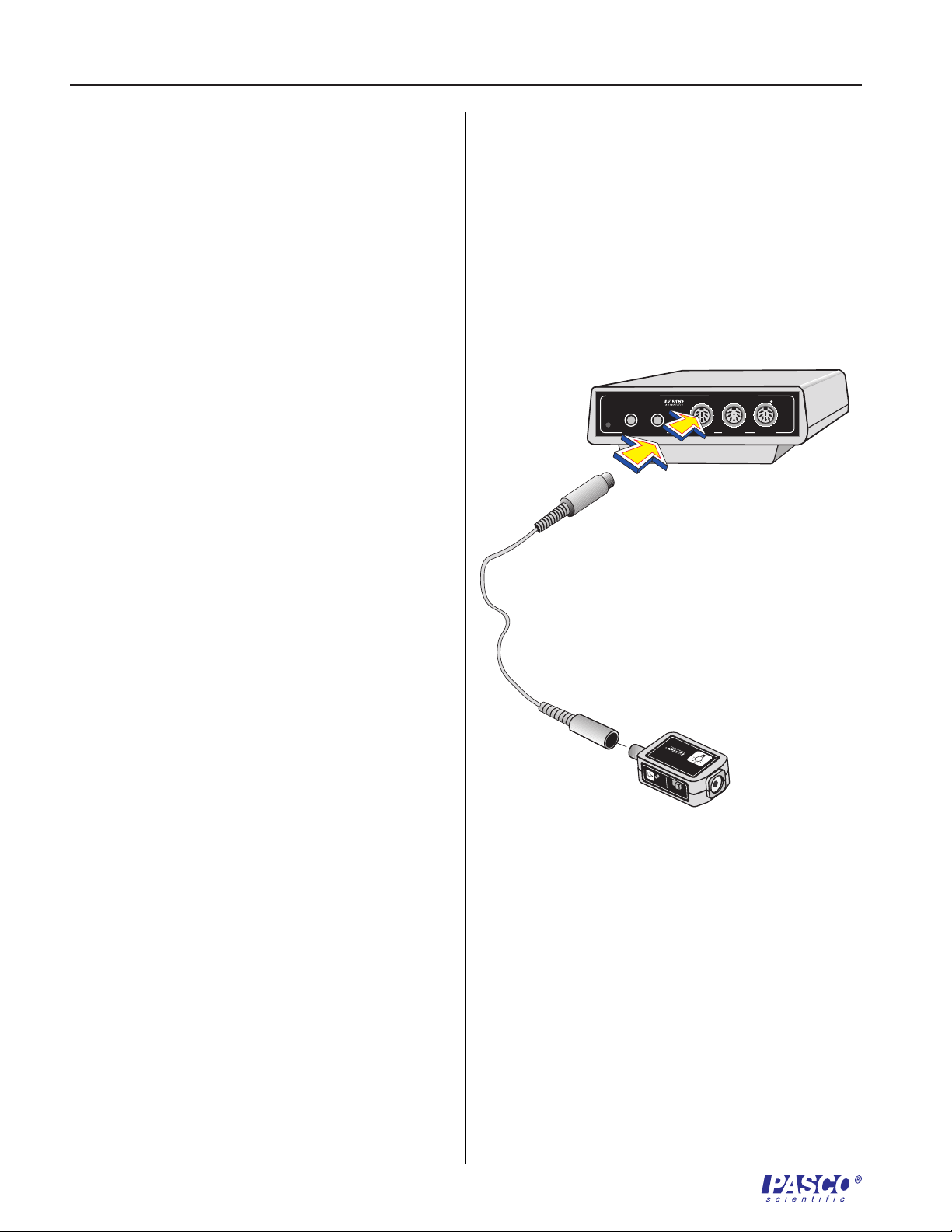
Figure 1
Connecting the amplifier box to the interface bo x
Science Workshop. Another useful resource is the
Quick Reference Card for Science Workshop.
Setting up the Equipment
1. Connect the Infrared Sensor unit to analog
channel A, B, or C of the Science Workshop
computer interface box using the cable with
the DIN connectors (Figure 1). Alternatively,
the unit can be plugged directly into the
analog channel jack without using the cable.
2. Select the appropriate gain setting on the
sensor box for the light levels to be measured
2
Page 3
012-06915B Infrared Sensor
10
1
100
GAIN
TARE
1
4
3
5
2
6
7
8
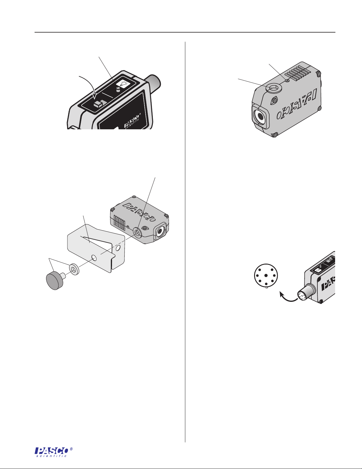
Tare
button
Adjust the gain
for the light
conditions
TARE
GAIN
1
10
100
FRARED SENSOR
Figure 2
Setting the Gain On the Infrared Sensor
shutter bracket
1/4-20
thumb-
screw
and washer
28
1/4-20 threaded
connector
Note the orientation of components as illustrated in
alignment hole
1/4-20 threaded
connector
Figure 4
Mounting connector and alignment hole
Figure 3. Mount the shutter bracket to the Infrared
Sensor unit, with the included hardware, as shown.
Do not over tighten thumbscrew.
Mounting on an Experimental Apparatus
Use the 1/4-20 threaded connector located on the
bottom of the sensor box to secure the Infrared
Sensor to an experimental apparatus (Figure 4).
The alignment hole fits over an alignment pin
included on some PASCO apparatuses.
DIN Connector Specifications
1: analog output (+), -10 to +10 V
2: analog output (-), signal ground
Figure 3
Installation of Shutter Bracket
3: (no connection)
4: + 5 V DC power
(Figure 2). The correct gain setting is the one
for which the intensity levels on the display
vary appropriately for measuring the relative
light intensity changes in your experiment.
Using the Shutter Bracket
3
Page 4

Infrared Sensor 012-06915B
5: power ground
6: +12 VDC power
7: -12 VDC power
8: (no connection)
Limited Warranty
PASCO scientific warrants the product to be free
from defects in materials and workmanship for a
period of one year from the date of shipment to the
customer. PASCO will repair or replace, at its
option, any part of the product which is deemed to
be defective in material or workmanship. The
warranty does not cover damage to the product
caused by abuse or improper use. Determination of
whether a product failure is the result of a
manufacturing defect or improper use by the
customer shall be made solely by PASCO
scientific. Responsibility for the return of
equipment for warranty repair belongs to the
customer. Equipment must be properly packed to
prevent damage and shipped postage or freight
prepaid. (Damage caused by improper packing of
the equipment for return shipment will not be
covered by the warranty.) Shipping costs for
returning the equipment after repair will be paid by
PASCO scientific.
Address: PASCO scientific
10101 Foothills Blvd.
Roseville, CA 95747-7100
Phone: (916) 786-3800
FAX: (916) 786-8905
email: techsupp@pasco.com
web: www.pasco.com
4
 Loading...