

Page 1
Instruction Sheet
for the PASCO
Model CI-6558 Rev A
A CCELERATION SENSOR
a
5
g
TARE
S
E
R
N
E
S
S
O
P
R
O
N
S
S
E
L
O
W
F
A
S
T
a
A
C
5
C
D
g
E
I
R
S
E
L
C
E
E
C
T
+
I
N
O
R
I-6
N
S
A
O
O
5
F
T
5
A
R
IO
8
C
S
P
C
E
O
N
E
N
S
L
S
I
E
O
T
R
I
R
O
A
N
T
I
O
N
-
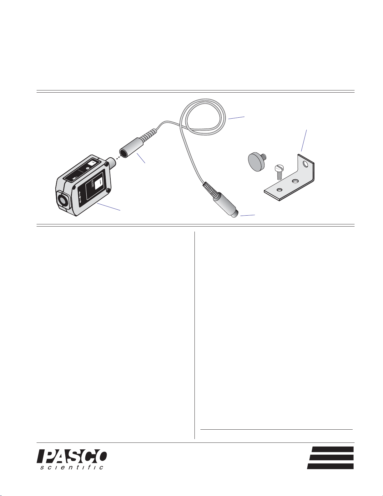
Acceleration
Sensor
DIN connector
interface cable
with 8-pin DIN
connectors
to computer interface
012-06361C
11/03
bracket for
attaching to
Dynamics Cart
Introduction
The PASCO CI-6558 Rev A Acceleration Sensor is
designed for use with any PASCO computer interface
and Data Studio to measure accelerations ranging up to 5
times the earth's gravitational field with an accuracy of
0.01 g (g = acceleration of gravity, 9.8 m/s2). The sensor
produces a bipolar output that may vary from +5 g to -5
g, depending on the direction of acceleration. The
Acceleration Sensor is capable of resolving changes in
acceleration on the order of 1 milli-g when a gain of 10 is
applied in Data Studio.
The Acceleration Sensor has two built-in features for
configuring it to a particular application: (1) a tare button,
used to set the output of the sensor to 0 regardless of the
acceleration being applied (allows the effect of the
earth's gravitational field to be nulled); (2) a filter with
two settings—"slow" or "fast", setting the frequency
response of the Acceleration Sensor to a range suitable
for the application.
For experiments such as measuring the acceleration of
elevators, roller coasters, and automobiles, select the
"slow" setting. The slow filter reduces errors due to high
frequency vibrations and noise. For applications
involving mechanical systems, such as cart collision
experiments, select the fast setting.
The Data Studio software will display the output of the
Acceleration Sensor in units of m/s
2
, or in terms of g.
Very small values of acceleration can be measured by
taring the sensor and adding gain in Data Studio.
Equipment
Equipment Included:
• Acceleration Sensor
• 6-foot cable with 8-pin DIN connectors
• bracket, thumbscrew, and bolt for attaching
Acceleration Sensor to a Dynamics Cart
Additional Equipment Required:
• Any PASCO Data Studio computer
interface (300, 500, 700 or 750 series for Macintosh
or Windows)
Additional Equipment Suggested:
• Dynamics Cart (ME-9430 or ME-9454)
• Dynamics Track (ME-9429A or ME-9452)
© 1997 PASCO scientific
®
10101 Foothills Blvd. • P.O. Box 619011 • Roseville, CA 95678-9011 USA
Phone (916) 786-3800 • FAX (916) 786-8905 • web: www.pasco.com
better
ways to
teach science
Page 2
Acceleration Sensor
012-06361C
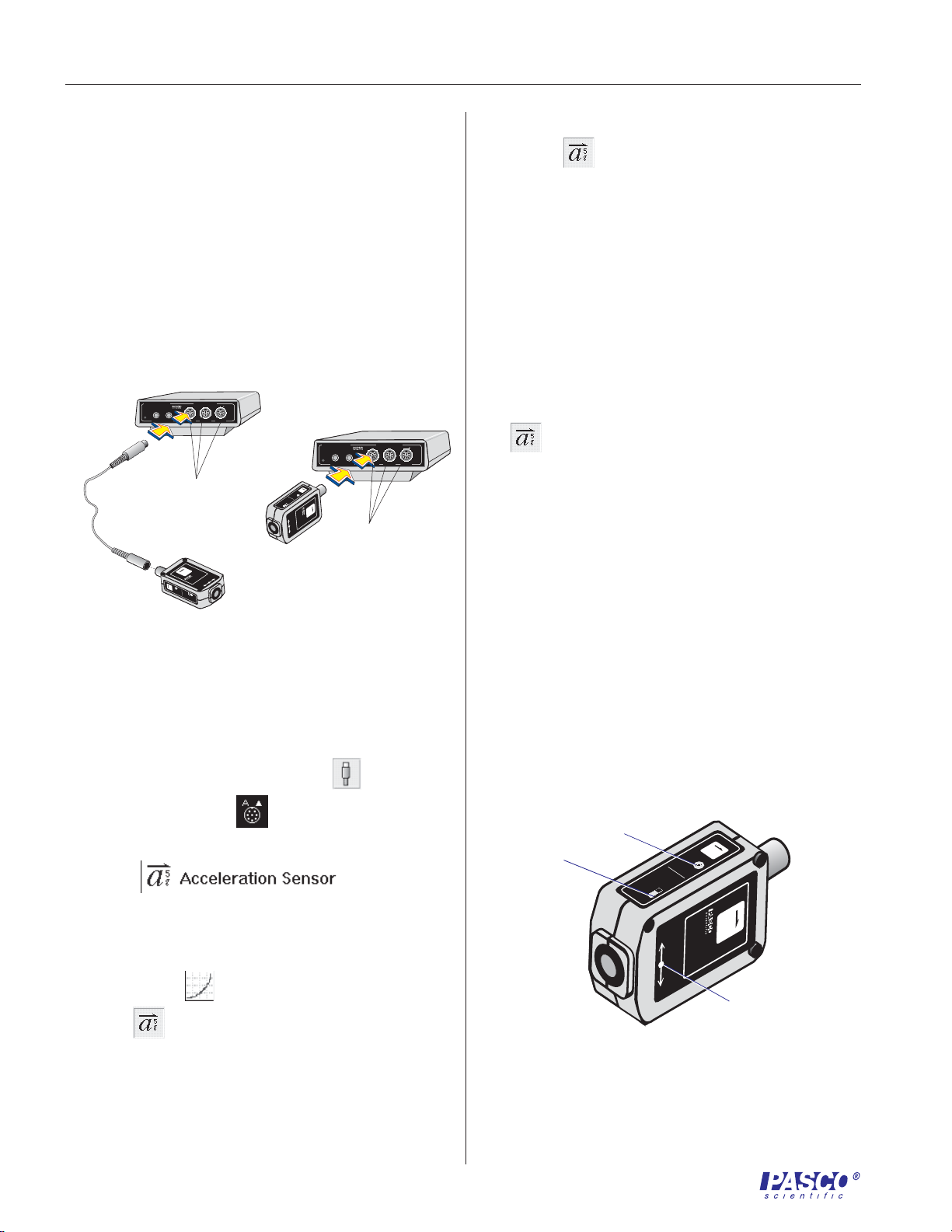
Setup Procedure
Setting Up Data Studio
1 Connect the Acceleration Sensor to any analog
channel on the computer interface box with interface
cable (Figure 1a),
or
insert the DIN plug of the Acceleration Sensor into
the jack of any analog channel on the computer
interface box (Figure 1b).
ANALOG CHANNELS
™
ScienceWorkshop
®
s
n
A
C
500
Interface
E
S
R
S
1
A
P
T
G
O
O
L
a
DIGITAL CHANNELS
B
2
ON
GAIN
=
GAIN
1,10:ISOLATED
1,10: REF TO GND
Plug into
any analog
channel.
5
8
g
5
5
6
N
-
I
C
a
TIO
R
O
ERA
NS
E
EL
C
C
A
SE
CC
F
O
A
N
O
I
T
C
E
R
I
D
+
5
g
a
E
R
A
E
R
T
S
O
N
S
O
N
P
E
S
S
E
W
R
T
O
S
L
S
A
F
=
=
GAIN
1: REF TO GND
b
ANALOG CHANNELS
™
ScienceWorkshop
®
s
A
500
Interface
E
S
R
S
1
P
T
G
O
O
L
DIGITAL CHANNELS
a
5
g
T
A
R
E
S
E
R
N
E
S
S
O
P
R
O
N
S
S
E
L
O
W
F
A
S
T
a
A
C
5
C
D
g
E
I
R
S
E
L
C
E
E
C
T
+
I
N
O
R
I
-
N
S
6
A
O
O
5
F
T
5
A
R
IO
8
C
S
P
C
E
O
N
E
N
S
L
S
I
E
O
T
R
I
R
O
A
N
T
I
O
N
-
Plug into any
B
2
ON
=
GAIN
1,10:ISOLATED
1,10: REF TO GND
analog
N
O
I
T
-
A
R
E
L
R
N
O
O
S
I
N
T
I
E
S
S
O
P
channel.
2
5 To select units of g or m/s
the icon (
) and select the Measurements tab.
for the display double click
To select units of g, click the check box next to
Acceleration (g).
To select units of m/s
2
, click the check box next to
Acceleration, A (m/s/s) .
➤➤
➤
Note: Open additional display windows by
➤➤
following the procedure in steps 4 and 5.
2
6 If accelerations of less than 1 g or 10 m/s
are to be
measured, the sensitivity may be increased to
medium (10X gain) as follows:
Double-click on the Acceleration Sensor icon
(
n
C
=
=
GAIN
GAIN
1: REF TO GND
) in the setup window to open the Acceleration
Sensor dialog box. Click on the arrow under the
Calibration tab for Sensitivity and select Med (10x)
in the pop-up menu.
7 The default sampling rate is 10 samples/second.
Change the sampling rate, if required, by clicking the
General tab and using the - and + buttons to select the
desired sampling rate.
Figure 1. Connecting the Acceleration Sensor to the
computer interface.
2 Open the Data Studio program. In the setup window,
click and drag the analog plug icon (
analog channel icon (
) that corresponds to the
) to the
port the Acceleration Sensor is plugged into.
3 Select
from the pop-up
menu.
4 Open a display window, such as the Graph
display, by dragging and dropping the appropriate
display icon (
icon (
).
) to the Acceleration Sensor
Adjusting the Acceleration Sensor
1 Set the filter switch to slow for most applications. Set
it to high for collision experiments or similar
mechanical experiments (Figure 2).
2 Press the tare button to set the sensor to 0 under the
current conditions (Figure 2).
tare button
filter switch:
fast or slow
RESPONSE
SLOW
FAST
Figure 2. Sensor setup controls and arrow indicator
of the direction of sensitivity.
TAR
E
SENSOR
DIRECTION OF ACCELERATION
SENSOR
+
SENSOR
POSITION
-
a
5
g
a
ACCELERATION
5
g
C
I-6
5
5
8
indicator of direction
of sensitivity and
sensor position
2
Page 3

012-06361C
1
4
3
5
2
6
7
8
FAST
SLOW
SENSOR
RESPONSE
a
5
g
TARE
Acceleration Sensor
Maintaining the Direction of Sensitivity
The sensing unit of the Acceleration Sensor is oriented so
that the line of greatest sensitivity follows the arrow
indicating the direction of acceleration (Figure 2).
Experiments should be conducted with the arrow on the
label of the Acceleration Sensor oriented along the same
line as the direction of the acceleration to be measured.
Calibrating the Acceleration Sensor
The Acceleration Sensor is factory calibrated and is
2
accurate to about 0.05 g or 0.5 m/s
. For most
experiments, no further calibration is required. However,
the following calibration procedure may be performed to
maximize the Acceleration Sensor's accuracy.
1 Double click the Acceleration Sensor icon (
) in
the setup window of Data Studio then click the Calibration tab.
2 In the Calibration dialog, enter 1.000 in the High
Value dialog box in the pop-up menu, and -1.000 in
the Low Value dialog box.
➤➤
➤
Note: For a detailed description of the
➤➤
calibration process, access the Data Studio Help
menu and click Setup Information, Setting up a
sensor.
Mounting on a Dynamics Cart
thumbscrew
bolt
bracket
threaded connector
Dynamics Cart
Acceleration
Sensor
3 Place the sensor flat on a level surface with the arrow
indicating direction of sensitivity parallel to the
ground (Figure 3a) and press the tare button.
a
Rotate
180°
5
g
8
5
5
6
-
a
I
N
C
O
I
T
A
R
R
N
E
O
O
I
L
T
S
A
E
R
N
-
E
C
L
E
E
C
S
C
C
A
A
R
F
O
O
N
S
O
N
I
N
T
O
E
I
I
S
S
T
C
O
E
P
R
I
D
5
g
+
a
E
R
A
T
E
R
S
O
N
S
O
N
P
E
S
S
E
W
R
O
T
L
S
S
A
F
b
a
5
g
T
A
R
E
S
R
EN
ES
S
PO
O
S
R
N
LO
SE
W
F
AS
T
a
A
CC
D
I
5
R
E
g
E
S
C
LE
+
EN
T
I
CI-6558
O
R
N
SO
O
ATIO
F
A
S
R
C
P
E
C
O
N
E
S
S
N
L
I
T
O
E
I
R
O
R
A
N
T
I
O
N
-
Figure 4. Mounting the Acceleration Sensor to the
bed of the Dynamics Cart.
Operation Specifications:
• Maximum usable acceleration: ± 5 g or 50 m/s
• Sensor Output: 1 V/g
• Accuracy: 0.01 g or 0.1 m/s
• Resolution: 0.001 g or 0.01 m/s
2
2
2
• Alignment error of the acceleration sensing element:
Press the
tare button
±1° (Alignment error is defined as the difference
between the true and indicated axis of sensitivity.)
• Absolute maximum acceleration without damaging
Figure 3. Positions of the Acceleration Sensor
during the calibration procedure.
4 Orient the sensor so the + arrow on the label is
pointing toward the ground (Figure 3b).
5 Click
beside the High Value dialog box.
6 Rotate the sensor 180° around its major axis so the
– arrow points toward the ground (Figure 3b).
7 Click
8 Click OK. The Acceleration Sensor is now calibrated.
beside the Low Value dialog box.
the sensing element: 1000 g for 0.5 ms
DIN Connector Specifications
1: analog output (+), 0 to 10 V
2: analog output (-), signal ground
3: (no connection)
4: + 5 V DC power
5: power ground
6: +12 V DC power
7: -12 V DC power
8: (no connection)
3
Page 4

Acceleration Sensor
012-06361C
Suggested Experiment
Verify the Acceleration Sensor's Performance in the
Earth's Gravitational Field
1 Connect the Acceleration Sensor to the computer
interface with the interface cable (see Figure 1a) and
set up Data Studio as detailed on page 2. Open a
Digital Display and select Acceleration (g) from the
pop-up menu. Set the filter switch on the sensor to
SLOW.
2 Place the sensor flat on a level surface with the arrow
indicating direction of sensitivity parallel to the
ground (Figure 3a) and press the tare button.
3 Orient the sensor so the arrow on the label is
perpendicular to the ground (see Figure 3b). Click
Monitor Data under the Experiment selection menu in
Data Studio.
4 Observe that Data Studio is displaying a value for ac-
celeration of either plus or minus 1 g.
5 Rotate the sensor 180° around its major axis so the
arrows point in the opposite direction.
Suggested Activities
1 Measure the acceleration of a Dynamics Cart down an
inclined Dynamics Track.
2 Measure the acceleration during collision of a
Dynamics Cart.
3 Measure the acceleration during free fall.
4 Measure the acceleration of an elevator, automobile,
or roller coaster using the remote data logging
capability of the 500 series computer interface.
Copyright Notice
The PASCO scientific 012-06361 instruction sheet is
copyrighted and all rights reserved. However, permission
is granted to non-profit educational institutions for
reproduction of any part of the Acceleration Sensor
instruction sheet providing the reproductions are used
only for their laboratories and are not sold for profit.
Reproduction under any other circumstances, without the
written consent of PASCO scientific, is prohibited.
6 Observe that Data Studio now displays 1 g with the
opposite sign as observed before.
7 Can you imagine a way to measure the tilt angle of
the sensor? (Hint: tilt angle = sin
-1
(acceleration
in g).
5
g
a
CI-6558
ACCELERATION
SENSOR
DIRECTION OF ACCELERATION
SENSOR
+
POSITION
0 g
DIRECTION OF ACCELERATION
SENSOR
ACCELERATION
CI-6558
a
g
–
5
0 g
DIRECTION OF ACCELERATION
ACCELERATION
+
SENSOR
POSITION
SENSOR
CI-6558
–
+1 g
a
5
g
g
5
CI-6558
a
-1 g
SENSOR
ACCELERATION
–
SENSOR
POSITION
+
DIRECTION OF ACCELERATION
POSITION
+
–
SENSOR
+
–
Figure 5. Response of the Acceleration Sensor to the
earth's gravitational field.
Author: Steve Miller
Editor: Sunny Bishop
Limited Warranty
PASCO scientific warrants the product to be free from
defects in materials and workmanship for a period of one
year from the date of shipment to the customer. PASCO
will repair or replace, at its option, any part of the product
which is deemed to be defective in material or
workmanship. The warranty does not cover damage to the
product caused by abuse or improper use. Determination
of whether a product failure is the result of a
manufacturing defect or improper use by the customer
shall be made solely by PASCO scientific. Responsibility
for the return of equipment for warranty repair belongs to
the customer. Equipment must be properly packed to
prevent damage and shipped postage or freight prepaid.
(Damage caused by improper packing of the equipment
for return shipment will not be covered by the warranty.)
Shipping costs for returning the equipment after repair
will be paid by PASCO scientific.
Address: PASCO scientific
10101 Foothills Blvd.
P.O. Box 619011
Roseville, CA 95678-9011
Phone: (916) 786-3800
FAX: (916) 786-8905
email: techsupp@pasco.com
web: www.pasco.com
4
 Loading...