

Page 1
Instruction Sheet
for the PASCO
Model CI-6556
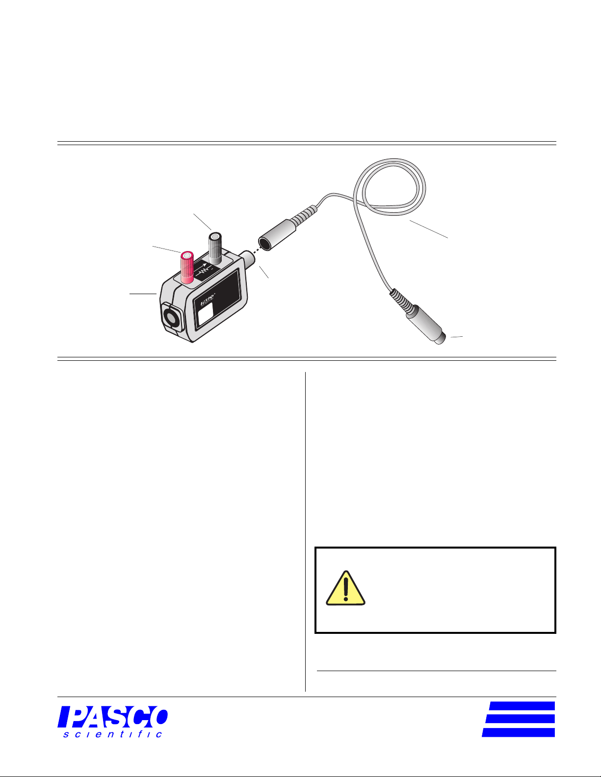
- terminal
012-06431B
5/97
$1.00
CURRENT SENSOR
+ terminal
CURRENT
1.00Ω
Current Sensor
+
CI-6556
MAX CURRENT: ±1.5A
CURRENT
SENSOR
DIN connector
I
Introduction
The PASCO CI-6556 Current Sensor is designed to be
used with a PASCO computer interface to measure
currents of ±1.5 amperes.
The Current Sensor can be plugged directly into any
analog channel (A,B, or C) on the PASCO 700i Science
Workshop interface or analog channel A on the 300i or
500i Science Workshop interface. This is because the
Current Sensor should only be connected to a non-ground
referenced, differential input.
interface cable with
8-pin DIN
connectors
to computer interface
Equipment
Equipment Included:
• Current Sensor
• 6-foot cable with 8-pin DIN connectors
Additional Equipment Required:
• Any PASCO Science W orkshop
(300, 500, or 700 series for Macintosh or Windows)
or the 6500 series interface for DOS
• patch cords (SE-9415)
computer interface
Current passing through the two input connectors
develops a voltage across the 1.00 Ω, 2 W resistor in the
Current Sensor. The voltage developed at the resistor is
related to the current according to Ohm's Law:
V = I x R
(where V = voltage in volts, I = current in amps, and R =
resistance in ohms).
Since the Current Sensor utilizes a 1.00 Ω resistor, the
voltage seen across the resistor is equal to the current
flowing through the resistor. The computer interface
channels this voltage into Science Workshop, which
reports the value in amperes (A) of current.
®
10101 Foothills Blvd. • P.O. Box 619011 • Roseville, CA 95678-9011 USA
Phone (916) 786-3800 • FAX (916) 786-8905 • web: www.pasco.com
Do not connect to currents greater
than 1.5 A. Connecting to a source
that causes a current of greater than
1.5 A will permanently damage the
Current Sensor.
© 1997 PASCO scientific
better
ways to
teach science
Page 2
Current Sensor
012-06431B
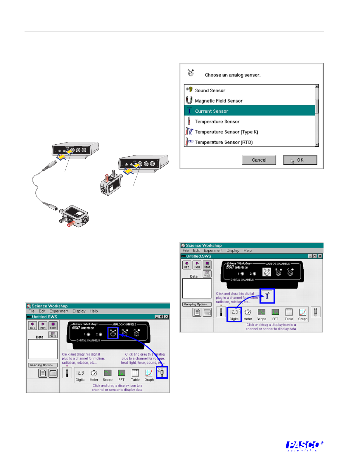
Setup Procedure
Science Workshop Setup
➀ Connect the Current Sensor to any differential input
analog channel on the computer interface box with
interface cable (Figure 1a),
or
insert the DIN plug of the Current Sensor into the
jack of any differential input analog channel on the
computer interface box (Figure 1b).
ANALOG CHANNELS
™
ScienceWorkshop
®
s
n
A
C
500
Interface
E
S
R
S
1
A b
a
P
T
G
O
O
L
DIGITAL CHANNELS
B
2
ON
=
GAIN
GAIN
=
GAIN
1,10:ISOLATED
1,10: REF TO GND
1: REF TO GND
Plug into a
differential
input analog
channel.
SENSOR
CURRENT
CI-6556
I
MAX CURRENT: ±1.5A
1.00Ω
+
CURRENT
=
ANALOG CHANNELS
™
ScienceWorkshop
®
s
n
A
C
2
ON
=
GAIN
1,10:ISOLATED
Plug into a
B
=
=
GAIN
GAIN
1,10: REF TO GND
1: REF TO GND
500
Interface
E
S
R
S
1
P
T
G
O
O
L
DIGITAL CHANNELS
CURRENT
1.00Ω
+
CI-6556
MAX CURRENT: ±1.5A
CURRENT
SENSOR
I
differential
input analog
channel.
➂ Select "Current Sensor" from the drop-down menu
(Figure 3).
Figure 3. Setting up the Current Sensor in Science
Workshop.
➃ Open a display window, such as the Digits display, by
dragging and dropping the appropriate display icon to
the Current Sensor icon (Figure 4).
Figure 1. Connecting the Current Sensor into the
computer interface.
➁ Open the Experiment Setup window in
Science W orkshop. Click and drag the analog plug icon
to the analog channel icon that matches the analog
port you are using for the Current Sensor (Figure 2).
Figure 2. Activating the analog channel in
Science W orkshop.
Figure 4. Opening a Display window in Science W orkshop.
➄ Additional display windows can be opened by
following the procedure in step 4.
2
Page 3

012-06431B
4
Current Sensor
Equipment Setup
➀ Break the circuit at the point the current flow is to be
measured and insert the Current Sensor using standard
banana plug connectors or other suitable means
(Figure 5).
a
I
patch cords
MAX CURRENT: ±1.5A
CI-6556
CURRENT
I
SENSOR
or
b
I
Mounting on an Experimental Apparatus
➀ Use the 1/4–20 threaded screw connector located on
the bottom of the sensor box to secure the Current Sensor
to an experimental apparatus (Figure 6). The alignment
hole fits over an alignment pin included on some PASCO
apparatuses.
alignment hole
1/4–20 threaded
screw connector
Figure 6. Connections for mounting on some PASCO
experimental apparatuses.
to computer interface
MAX CURRENT: ±1.5A
CI-6556
CURRENT
I
SENSOR
Figure 5. Equipment Setup for measuring current across a
circuit with a DC (a) or AC (b) power source.
I
MAX CURRENT: ±1.5A
CI-6556
CURRENT
I
SENSOR
Warning! Do not connect the Current
Sensor directly across a voltage source
or unloaded ciruit. Connecting to a
source that causes a current of greater
than 1.5 A to flow will permanently
damage to the sensor.
DIN Connector Specifications
1: analog output (+),
-1.5 to 1.5 V
2: analog output (-),
signal ground
3: (no connection)
4: (no connection)
5: (no connection)
1
4
3
5
2
Specifications:
resolution: 5 mA (1X gain in Science Workshop)
0.5 mΑ (10X gain in Science Workshop)
maximum current input: 1.5 A*
maximum differential voltage: 1.5 V*
maximum common mode voltage: ± 10 V*
*DC or AC RMS (root mean square)
The exclamation point within an
equilateral triangle is intended to alert
the user of the presence of important
operating and maintenance (servicing)
instructions in the literature
accompanying the device.
CURRENT
1.00Ω
+
3
Page 4

Copyright, W arranty, and Equipment Return
Please—Feel free to duplicate this manual
subject to the copyright restrictions below.
Copyright Notice
The PASCO scientific 012-06431B instruction sheet is
copyrighted and all rights reserved. However, permission
is granted to non-profit educational institutions for
reproduction of any part of the Current Sensor instruction
sheet providing the reproductions are used only for their
laboratories and are not sold for profit. Reproduction
under any other circumstances, without the written
consent of PASCO scientific, is prohibited.
Limited Warranty
PASCO scientific warrants the product to be free from
defects in materials and workmanship for a period of one
year from the date of shipment to the customer. PASCO
will repair or replace, at its option, any part of the product
which is deemed to be defective in material or workmanship. The warranty does not cover damage to the product
caused by abuse or improper use. Determination of
whether a product failure is the result of a manufacturing
defect or improper use by the customer shall be made
solely by PASCO scientific. Responsibility for the return
of equipment for warranty repair belongs to the customer.
Equipment must be properly packed to prevent damage
and shipped postage or freight prepaid. (Damage caused
by improper packing of the equipment for return shipment will not be covered by the warranty.) Shipping costs
for returning the equipment after repair will be paid by
PASCO scientific.
Warning
Equipment Return
Should the product have to be returned to PASCO
scientific for any reason, notify PASCO scientific by
letter, phone, or fax BEFORE returning the product.
Upon notification, the return authorization and shipping
instructions will be promptly issued.
➤ ➤
➤ NOTE: NO EQUIPMENT WILL BE
➤ ➤
ACCEPTED FOR RETURN WITHOUT AN
AUTHORIZATION FROM PASCO.
When returning equipment for repair, the units must be
packed properly. Carriers will not accept responsibility
for damage caused by improper packing. To be certain
the unit will not be damaged in shipment, observe the
following rules:
➀ The packing carton must be strong enough for the
item shipped.
➁ Make certain there are at least two inches of packing
material between any point on the apparatus and the
inside walls of the carton.
➂ Make certain that the packing material can not shift in
the box, or become compressed, allowing the
instrument come in contact with the packing carton.
Address: PASCO scientific
10101 Foothills Blvd.
P.O. Box 619011
Roseville, CA 95678-9011
Phone: (916) 786-3800
Application of electrical voltage and/or
currents in excess of the values listed in the
product specification section will damage this
product, create a safety hazard, and may
endanger the operator. This device does not
use or produce voltages that exceed 42.4 VAC
peak, 30 VAC RMS, or 60 VDC.
FAX: (916) 786-8905
email: techsupp@pasco.com
Credits
Author: Steve Miller
Editor: Sunny Bishop
 Loading...