

Page 1

Includes
Teacher's Notes
and
Typical
Experiment Results
Instruction Manual and
012-06852A
11/98
Experiment Guide for
the
PASCO scientific
Model CI-6539A
EKG SENSOR
EKG Electrodes
RED
+
GRN
-
REF
BLK
CI-6539A
EKG
FOR REPLACEMENT
EKG ELECTRODES
535-020
USE PASCO PART NO.
SENSOR
OR EQUIVALENT
(ELECTROCARDIOGRAM)
© 1998 PASCO scientific $5.00
Page 2

Page 3

012–06852A EKG Sensor
T able of Contents
Section Page
Copyright, Warranty, and Equipment Return ........................................................................ ii
Introduction .............................................................................................................................. 1
Equipment................................................................................................................................. 1
Theory ....................................................................................................................................... 2
The Electrocardiogram.................................................................................................... 4
Suggested Reading.......................................................................................................... 5
Setup.......................................................................................................................................... 6
Connecting the EKG Sensor to a Person......................................................................... 6
Using the EKG Sensor with Science Workshop® Interfaces........................................... 7
Suggested Experiments ............................................................................................................. 8
Resting Ekg.....................................................................................................................8
EKG After Mild Exercise................................................................................................ 8
EKG and Different Body Positions................................................................................. 8
EKG and Mild Stimulants............................................................................................... 8
Technical Support.................................................................................................... Back Cover
i
Page 4

Copyright, Warranty , and Equipment Return
Please—Feel free to duplicate this manual
subject to the copyright restrictions below.
Copyright Notice
The PASCO scientific 012-06852A EKG Sensor
manual is copyrighted and all rights reserved.
However, permission is granted to non-profit
educational institutions for reproduction of any part of
the manual providing the reproductions are used only
for their laboratories and are not sold for profit.
Reproduction under any other circumstances, without
the written consent of PASCO scientific, is prohibited.
Limited Warranty
PASCO scientific warrants the product to be free from
defects in materials and workmanship for a period of
one year from the date of shipment to the customer.
PASCO will repair or replace at its option any part of
the product which is deemed to be defective in
material or workmanship. The warranty does not cover
damage to the product caused by abuse or improper
use. Determination of whether a product failure is the
result of a manufacturing defect or improper use by the
customer shall be made solely by PASCO scientific.
Responsibility for the return of equipment for
warranty repair belongs to the customer. Equipment
must be properly packed to prevent damage and
shipped postage or freight prepaid. (Damage caused by
improper packing of the equipment for return
shipment will not be covered by the warranty.)
Shipping costs for returning the equipment after repair
will be paid by PASCO scientific.
Equipment Return
Should the product have to be returned to PASCO
scientific for any reason, notify PASCO scientific by
letter, phone, or fax BEFORE returning the product.
Upon notification, the return authorization and
shipping instructions will be promptly issued.
ä
NOTE: NO EQUIPMENT WILL BE
ACCEPTED FOR RETURN WITHOUT AN
AUTHORIZATION FROM PASCO.
When returning equipment for repair, the units must
be packed properly. Carriers will not accept
responsibility for damage caused by improper packing.
To be certain the unit will not be damaged in
shipment, observe the following rules:
➀ The packing carton must be strong enough for the item
shipped.
➁ Make certain there are at least two inches of packing
material between any point on the apparatus and the
inside walls of the carton.
➂ Make certain that the packing material cannot shift in
the box or become compressed, allowing the
instrument come in contact with the packing carton.
Address: PASCO scientific
10101 Foothills Blvd.
Roseville, CA 95747-7100
Credits
Author: Larry Fulton
ii
Phone: (916) 786-3800
FAX: (916) 786-3292
email: techsupp@pasco.com
web: www.pasco.com
Page 5

012–06852A EKG Sensor
Introduction
The PASCO CI-6539A EKG (Electrocardiogram) Sensor measures
cardiac electrical potential wave forms (voltages produced by the
heart as its chambers contract). The sensor is designed for use with a
PASCO computer interface as an educational aid; it is not intended for
medical diagnosis.
This sensor complements the PASCO CI-6535 Respiration Rate
Sensor.
The sensor consists of the electronics box with a cable for connecting
to the PASCO computer interface via a five pin DIN analog connector.
Three electrode leads enter the electronics box on the side opposite the
cable that attaches to the interface. The sensor’s circuitry isolates the
user from the possibility of electrical shock in two ways.
• The sensor signal is transmitted through an opto-isolation circuit.
• Power for the sensor is transferred through an isolation transformer.
The circuitry protects against accidental overvoltages of up to 4,000
volts.
The sensor comes with a package of one hundred silver/silver
chloride electrode patches that can be attached to the skin.
Equipment
Included:
• EKG Sensor unit
• package of 100 EKG electrodes
Additional Required:
• computer (PC or Macintosh)
• Science Workshop® computer interface
• Science Workshop® software version 2.2 or higher
Replacement Parts:
Item PartNumber
EKG electrodes (100) CI-6620
CI-6539A EKG Sensor
EKG Electrodes
RED
+
GRN
-
REF
BLK
CI-6539A
)
M
A
R
EKG
G
FOR REPLACEMENT
IO
D
EKG ELECTRODES
535-020
R
A
USE PASCO PART NO.
C
O
SENSOR
OR EQUIVALENT
R
T
C
E
L
(E
EKG electrodes
(removed from package)
package of 100
EKG electrodes
1
Page 6

EKG Sensor 012–06852A
Theory
Heart muscle cells are polarized at rest. This means the cells have
slightly unequal concentrations of ions across their cell membranes.
See Figure 1. An excess of positive sodium ions on the outside of the
membrane causes the outside of the membrane to have a positive
charge relative to the inside of the membrane. The inside of the cell
is at a potential that is about 90 millivolts (mV) less than the outside
of the cell membrane. The 90 mV difference is called the resting
potential. See Figure 1.
The typical cell membrane is relatively impermeable to the entry of
sodium. However, the stimulation of a muscle cell causes an increase
in its permeability to sodium. Some sodium ions migrate into the cell.
This causes a change (depolarization) in the electrical field around
the cell. This change in cell potential from negative to positive and
back is a voltage pulse called the action potential. In muscle cells the
action potential causes a muscle contraction. Other ions and charged
molecules are involved in the depolarization and the recovery back
to the polarized state. These include potassium, calcium, chlorine
and charged protein molecules. The effect of this depolarization and
repolarization for the entire heart can be measured on the skin
surface. This is an electrocardiogram (EKG). The depolarization of
the heart also leads to the contraction of the heart muscles and
therefore the EKG is also an indicator of heart muscle contraction
(although this is an indirect measurement).
+
+
+
+
outside
the cell
+
+
+
+
+
+
+
Figure 1
Animal Cell Membrane (sectional view)
lipid bylayer
layers of protein molecules
-
-
-
-
-
-
-
-
-
-
-
inside
the cell
The cells of the heart will depolarize without an outside stimulus; that
is, they will depolarize spontaneously. The group of cells that
depolarize the fastest is called the pacemaker (also known as the
sinoatrial or SA node). These cell are located in the right atrium.
The cells of the atria are all connected physically and thus the
depolarization of the cells of the pacemaker cause all the cells of both
atria to depolarize and contract almost simultaneously.
The atria and the ventricles are isolated from each other electrically
by connective tissue that acts like the insulation on an electric wire.
The depolarization of the atria does not directly affect the ventricles.
There is another group of cells in the right atria, called the
atrioventricular or AV node, that will conduct the depolarization of
the atria down a special bundle of conducting fibers (called the
Bundle of His) to the ventricles. In the muscle wall of the ventricles
are the Purkinje fibers, which are a special system of muscle fibers
that bring depolarization to all parts of the ventricles almost
2
Page 7

012–06852A EKG Sensor
simultaneously. This process causes a small time delay and so there
is a short pause after the atria contract before the ventricles contract.
Because the cells of the heart muscle are interconnected, this wave of
depolarization, contraction and repolarization spreads across all the
connected muscle of the heart. See Figure 2.
Sinoatrial (SA)
Node
Atrioventricular (AV)
Node
Bundle of His
(Atrioventricular Bundle)
Right Atrium
Figure 2
Cross section of human heart
Right Ventricle
When a portion of the heart is polarized and the adjacent portion is
depolarized this creates an electrical current that moves through the
body. This current is greatest when one half of the connected portion
of the heart is polarized and the adjacent half is not polarized. The
current decreases when the ratio of polarized tissue to non-polarized
tissue is less than one-to-one. The changes in these currents can be
measured, amplified, and plotted over time. The EKG represents the
summation of all the actions potentials from the heart as detected on
the surface of the body and does not measure the mechanical
contractions of the heart directly.
The two atria contract due to the pacemaker and force blood into the
two ventricles. Shortly after this contraction the two ventricles
contract due to the signal conducted to them from the atria. The blood
leaves the two ventricles through pulmonary and aortic arteries. The
heart muscle cells recover their polarity and in another second the
cycle starts again.
Purkinje Fibers
(Conduction Myofibers)
➤➤
➤ Note: An excellent text about the
➤➤
electrocardiogram and other
phenomena of bioelectricity is Physics
with Health Science Applications by
Paul Peter Urone, ©1986, John Wiley
& Sons, Inc., New York.
3
Page 8
EKG Sensor 012–06852A
The Electrocardiogram
One part of a typical EKG (electrocardiogram) is a ‘flat line’ or trace
indicating no detectable electrical activity. This line is called the
Isoelectric line. Deviation from this line indicates electrical activity
of the heart muscles.
The first deviation from the Isoelectric line in a typical EKG is an
upward pulse followed by a return to the Isoelectric line. This is called
the P wave and it lasts about 0.04 seconds. This wave is caused by the
depolarization of the atria and is associated with the contraction of the
atria.
After a return to the Isoelectric line there is a short delay while the
heart’s AV node depolarizes and sends a signal along the
atrioventricular bundle of conducting fibers (Bundle of His) to the
Purkinje fibers, which bring depolarization to all parts of the ventricles
almost simultaneously.
After the AV node depolarizes there is a downward pulse called the
Q wave. Shortly after the Q wave there is a rapid upswing of the line
called the R wave followed by a strong downswing of the line called
the S wave and then a return to the Isoelectric line. These three waves
together are called the QRS complex. This complex is caused by the
depolarization of the ventricles and is associated the with the
contraction of the ventricles.
After a short period of time the sodium and calcium ions that have
been involved in the contraction migrate back to their original
location in a process that involves potassium ions and the sodium-
potassium pump. The movement of these ions generates an upward
wave that then returns to the Isoelectric line. This upward pulse is
called the T wave and indicates repolarization of the ventricles. The
atria repolarize
repolarization is not separately detectable.
during the QRS complex and therefore this
4
Page 9

012–06852A EKG Sensor
➤➤
➤ Note: If your EKG does not
The sequence from P wave to T wave represents one heart cycle. The
number of such cycles in a minute is called the heart rate and is
typically 70-80 cycles (beats) per minute at rest.
➤➤
correspond to the above numbers, DO
NOT BE ALARMED! These numbers
represent typical averages and many
Some typical times for portions of the EKG are given in Figure 3.
healthy hearts have data that fall
outside of these parameters. To read a
P-R interval ....120-200 milliseconds
QRS interval ....under 100 milliseconds
Q-T interval .....under 380 milliseconds
EKG effectively takes considerable
training and skill. This sensor is NOT
intended for medical diagnoses.*
Figure 3
Sample EKG Graph
*Suggested Reading
The following are authoritative sources of information concerning
the use of EKG machines and electocardiographs in medical practice.
Carr, Joseph J. and John M. Brown. Introduction to Biomedical
Equipment Technology. New York: John Wiley & Sons, 1981.
Conover, Mary Boudreau. Understanding Electrocardiography,
Seventh Edition. St. Louis: Mosby, 1996.
Wagner, Galen S. Mariott’s Practical Electrocardiography, Ninth
Edition. Baltimore: Williams and Wilkens, 1994.
5
Page 10
EKG Sensor 012–06852A
Setup
Connecting the EKG Sensor to a Person
Use three electrode patches per subject. The electrodes can be reused
but they tend to absorb moisture (they are very hygroscopic), and
therefore, reuse is not recommended.
• Because the electrical signal produced by the heart and detected
at the body’s surface is so small, it is very important that the
electrode patch makes good contact with the skin. Scrub the areas
of skin where the patches will be attached with a paper towel to
remove dead skin and oil.
• Avoid placing the electrodes over a large muscle, because the
electrical activity of the muscle will interfere with sensing the
voltage changes produced by the heart.
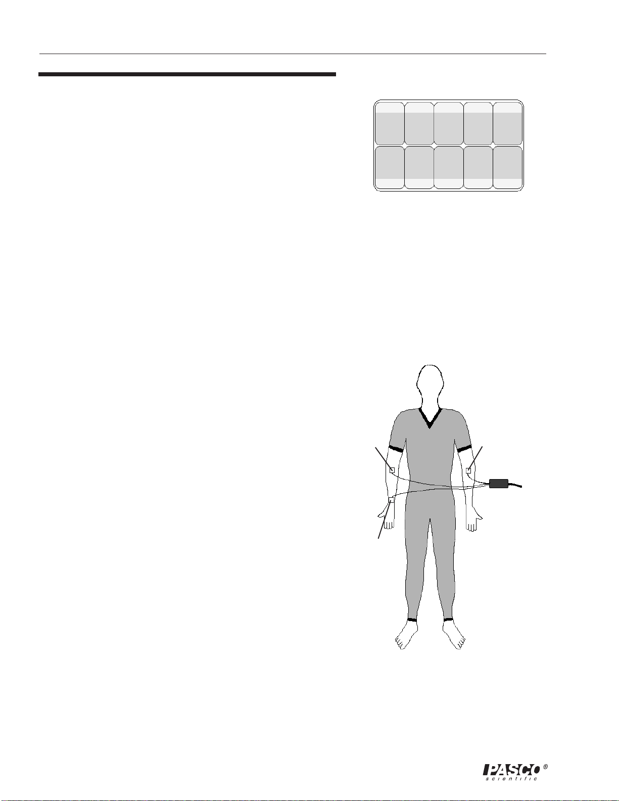
1. Peel three electrode patches from the backing paper. Firmly
place the first electrode on the right wrist. Place a second
electrode on the inside of the right elbow. Place the third
electrode on the inside of the left elbow. (This is one of several
possible arrangements for EKG electrodes on the body.) See
Figure 5.
• Be sure to place the electrodes with the tabs oriented in such a
way that the wire of the sensor can hang freely without twisting
the edge of the electrode patch.
2. Connect the micro alligator clips from the sensor to the tabs on
the edges of the electrode patches. See Figure 6.
Figure 4
Electrode patches on backing paper
➤➤
➤ Note: The electrodes should be kept
➤➤
in an airtight, clean, dry container for
storage.
negative
(green)
-
positive
(red)
+
EKG Sensor
to interface
• Connect the black (or “reference”) alligator clip to the right wrist
electrode patch. This is the reference point for the “Isoelectric”
line (baseline).
• Connect the green (or negative) alligator clip to the right elbow
electrode patch.
• Connect the red (or positive) alligator clip to the left elbow
electrode patch.
6
reference
(black)
Figure 5
Connecting the EKG Sensor to a person
Page 11

012–06852A EKG Sensor
Using the EKG Sensor with
Science Workshop™
Interfaces
The reading from the EKG Sensor in the Science Workshop software
has been scaled to the millivolt range. The reading is adjusted so that
zero volts represents the Isoelectric line.
1. Connect the EKG Sensor unit to analog channel A, B, or C of
the Science Workshop computer interface box using the cable
with the DIN connectors (Figure 7). Alternatively, the unit can
be plugged directly into the analog channel jack.
micro alligator clip
connected to tab of
electrode patch
electrode patch
on wrist
Figure 6
Connecting the micro alligator clips from the
sensor to the tabs on the edges of the
electrode patches
➤➤
➤ Note: This instruction sheet was
➤➤
written assuming that the user is
familiar with ScienceWorkshop. Users
can gain familiarity by working
through the tutorials provided with
ScienceWorkshop.
Figure 7
Connecting the EKG Sensor to the interface box
(ELECTROCARDIOGRAM)
SENSOR
EKG
CI-6539A
535-020
OR EQUIVALENT
USE PASCO PART NO.
EKG ELECTRODES
FOR REPLACEMENT
RED
+
BLK
REF
GRN
-
7
Page 12
EKG Sensor 012–06852A
Suggested Experiments
Resting EKG
• Measure the EKG of a person who is at rest. The person whose
EKG is being measured should remain calm and relaxed.
Encourage the person to breath normally. Use the Graph to
display the recorded data.
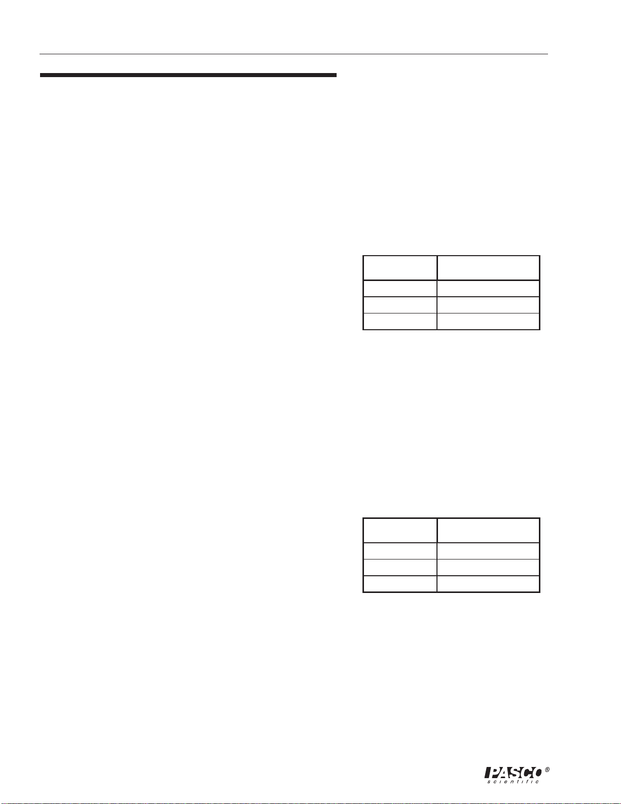
• Record the information specified in Table 1.1:
• Compare your values to the ones given earlier. What could
explain the differences?
T able 1.1 Interval Anal ysis
Time (milliseconds)Interval
EKG after Mild Exercise
• Measure the EKG of a person who is initially at rest. Disconnect
the sensor wires from the electrode patches, but leave the patches
on the person whose EKG is being measured. Have the person
exercise for three minutes by jogging in place or by “stepping-intime”.
• Reattach the sensor wires to the electrodes on the person within
thirty seconds after the exercise is done, and measure the EKG.
Compare the EKG after mild exercise to the rest EKG.
EKG and Different Body Positions
• Use body position as your independent variable. Measure the
rest EKG as before. Then have the person sit or stand or lie down.
Make no other changes. Note any changes in heart rate, interval
times, height of R wave, etc. In other words, compare your results
with your rest EKG.
EKG and Mild Stimulants
• Drink a couple of cups of strong caffeinated coffee as your
independent variable. (This might show less effect on people
who are accustomed to large amounts of coffee.) Compare your
results with the resting EKG results and mild exercise EKG
results.
P-Q
QRS
Q-T
T able 1.2 Heart Rate Analysis
Rate (per minute)Item
Minimum
Maximum
Average
8
Page 13
012–06852A EKG Sensor
Technical Support
Feedback
If you have any comments about the product or manual,
please let us know. If you have any suggestions on
alternate experiments or find a problem in the manual,
please tell us. PASCO appreciates any customer
feedback. Your input helps us evaluate and improve our
product.
To Reach PASCO
For technical support, call us at 1-800-772-8700
(toll-free within the U.S.) or (916) 786-3800.
fax: (916) 786-3292
e-mail: techsupp@pasco.com
web: www.pasco.com
Contacting Technical Support
Before you call the PASCO Technical Support staff, it
would be helpful to prepare the following information:
➤ If your problem is computer/software related, note:
- Title and revision date of software;
- Type of computer (make, model, speed);
- Type of external cables/peripherals.
➤ If your problem is with the PASCO apparatus, note:
- Title and model number (usually listed on the
label);
- Approximate age of apparatus;
- A detailed description of the problem/sequence of
events (in case you can’t call PASCO right away, you
won’t lose valuable data);
- If possible, have the apparatus within reach when
calling to facilitate description of individual parts.
➤ If your problem relates to the instruction manual,
note:
- Part number and revision (listed by month and year on
the front cover);
- Have the manual at hand to discuss your
questions.
9
Page 14

 Loading...