

Page 1
Instruction Sheet
for the PASCO
Model CI-6527A
012-08463B
Thermistor Sensor
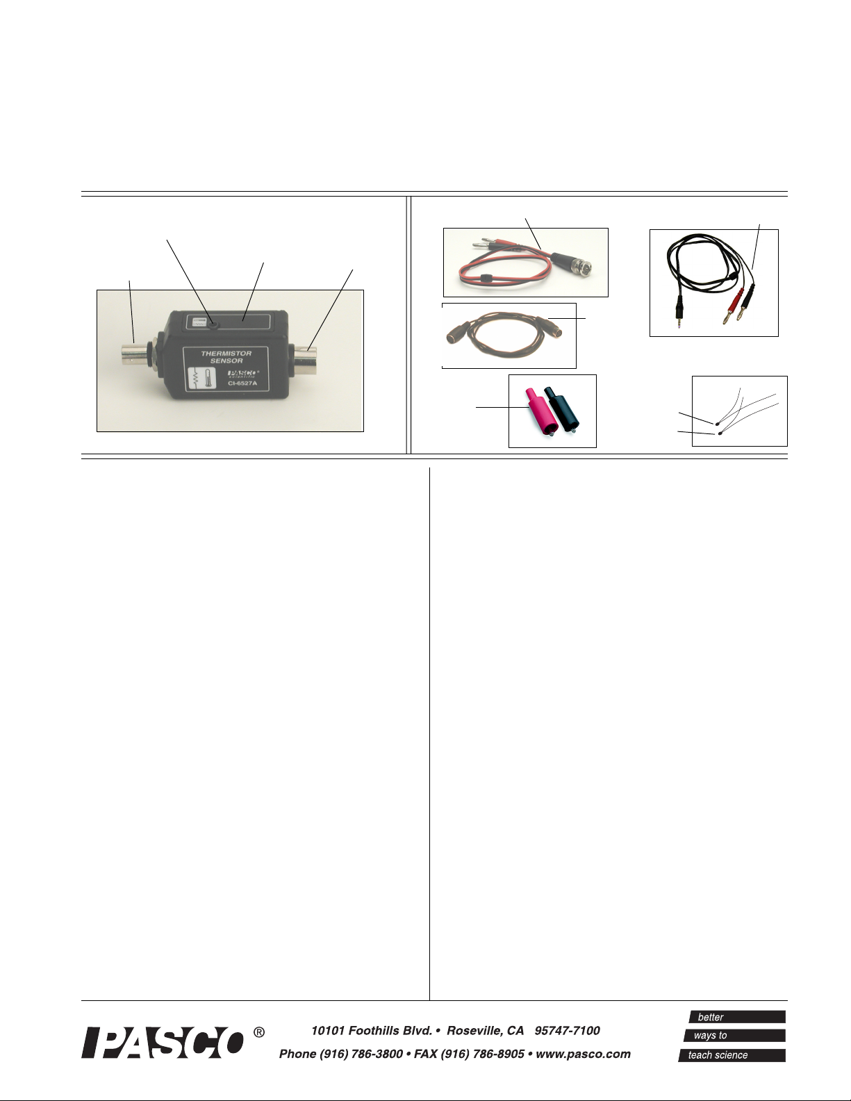
3.5 mm stereo jack
Thermistor Sensor
BNC jack
DIN
connector
Introduction
The CI-6527A Thermistor Sensor is used for
converting resistance measurements to temperature.
When used with a ScienceWorkshop® interface and
DataStudio software (version 1.8.5 or later), the
sensor allows you to directly measure the temperature
or simultaneously view both resistance and
temperature measurements in one graph.
BNC-to-dual banana plug
cable assembly
insulated
alligator clips
8-pin DIN
connecting
cable
100K thermistor
10K thermistor
3.5 mm stereo plug-todual banana plug cable
Equipment included:
• PASCO CI-6527A Thermistor Sensor
• Cable assembly, BNC-to-dual banana plug
• Cable assembly, 3.5 mm stereo-to-dual banana plug
• 8-pin DIN connecting cable
• Two insulated alligator clip adapters
• Thermistor, 100K ohm
The sensor is a two-thermistor circuit built into one
sensor case. Thermistors are resistors that change
resistance as their temperature changes. One
themistor circuit is used with PASCO 10K thermistors
that have a 3.5 mm male stereo jack.
The other thermistor circuit is 100K ohms and is used
with a BNC jack. The 100K circuit is designed for
use with a 100K thermistor, like that installed in the
PASCO Mechanical Equivalent of Heat Apparatus
(TD-8551A) or the Thermal Expansion Apparatus
(TD-8558A).
The stereo-to-dual banana plug cable is used to
connect the 10K thermister to apparatus requiring two
banana plugs such as the comupter-based Thermal
Expansion Apparatus (TD-8579A).
• Thermistor, 10K ohm
Additional equipment required:
• ScienceWorkshop® Interface
• DataStudio
® Software, version 1.8.5 or later
Applications
• Used with PASCO products that contain built-in
10K and 100K thermistors (i.e. TD-8579, TD8580, etc.)
• Thermal expansion studies
• Mechanical equivalent of heat
• Energy transfer studies
• Thermodynamics
Page 2
Thermistor Sensor 012-08463B
Thermistor Description
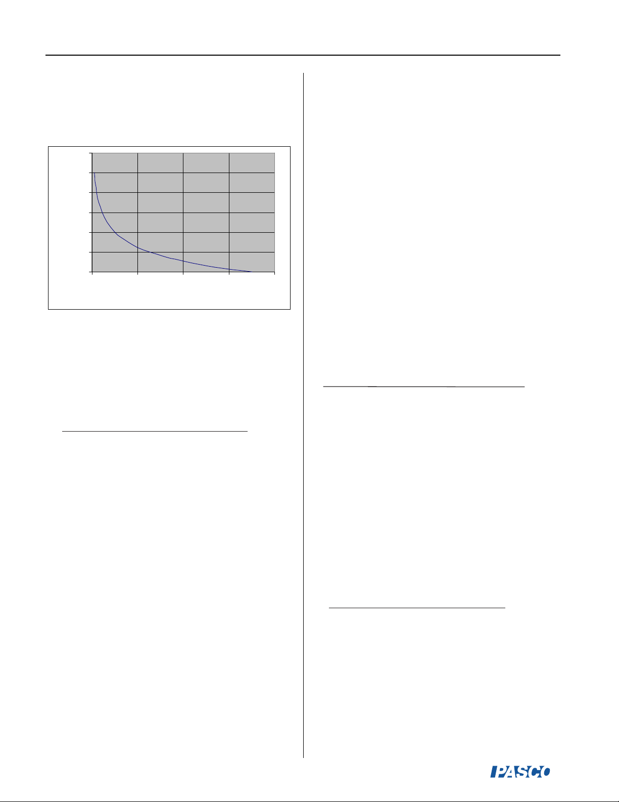
Figure 1 illustrates a typical resistance vs. temperature
curve for a 100K ohm thermistor.
120
100
80
60
40
Temperature( ºC)
20
0
0 100,000 200,000 300,000 400,000
Resistance (ohms)
Thermistors have a negative temperature coefficient.
As the temperature increases, the resistance of the
thermistor decreases. The Steinhart-Hart equation is
used to convert from resistance to temperature, where
T in degrees Celsius is
1
-4
(
8.25x10⁻⁴+2.05x10
and R
is the resistance in ohms.
100
.
ln(R100) + 1.14x10
10K thermistor - The 10K thermistor wire plugs into
the 3.5 mm jack and has an output voltage ranging
from 0 to -10 volts. The DataStudio software converts
the voltage to resistance and temperature.
100K thermistor - The 100K thermistor plugs into the
BNC jack and outputs a voltage ranging from 0 to +10
volts. The DataStudio software converts the voltage to
resistance and temperature.
Figure 1
-7
.
ln(R100)
-273.15
3
)
Electronic Circuitry and Internal
Operation
10K Thermistor Circuit - The 10K thermistor circuit
uses a precision voltage source and voltage divider to
determine the thermistor’s resistance. The thermistor
(Rt) is one resistor, and a 13K resistor (R
other in a two-resistor voltage divider network. In the
sensor housing, the reference resistor, voltage
regulator, and filter capacitor comprise the remainder
of the network. The relationship of the 10K
thermistor’s resistance (Rt) to voltage output (V
Rt=-V
out*Rref
where V
/(V
is 10V reference voltage. R
ref
ref-Vout
)
The normalized resistance is R10=Rt/10,000.
The Steinhart equation is used to convert from
resistance to temperature, where T, the temperature in
degrees Celsius is
1
-6
2
.
+ 8.37x10
ln(R10)
(
3.35x10⁻³+2.56x10
and R
is the normalized resistance of the thermistor
10
-4
.
ln(R10) + 2.38x10
in ohms.
100K Thermistor Circuit - The 100K thermistor
circuit outputs a positive voltage that is directly
proportional to the resistance of the resistor. The range
of resistance over which the sensor functions is 0 to
360K ohms. This resistance range maps into a 0 to 10
VDC output from the sensor. The relationship is Rt =
36,000*V
. The normalized resistance R
out
100,000. The Steinhart-Hart equation is used to
convert from resistance to temperature, where T, the
temperature in degrees Celsius is
1
(
8.25x10⁻⁴+2.05x10
-4
.
ln(R100) + 1.14x10
-7
.
ln(R100)
) is the
ref
is 13 Kohms.
ref
-8
3
.
ln(R10)
100=Rt
-273.15
3
)
out
-273.15
)
) is
/
When the Thermistor Sensor is connected to a
ScienceWorkshop interface, DataStudio determines
which thermistor, the 10K or the 100K, is connected to
the unit by the polariy of the V
signal, as long as the
out
thermistors are connected appropriately (10K to the
stereo jack and 100K to the BNC connector).
2
and R
100
in ohms.
is the normalized resistance of the thermistor
®
Page 3
012-08463B Thermistor Sensor
Connecting the Thermistor Sensor to
a Computer Interface
1. Connect the 8-pin DIN plug of the Thermistor Sensor
into analog channel A, B, or C of a ScienceWorkshop
computer interface (Figure 2a).
or
Use the supplied DIN cable to connect the Thermistor
Sensor to the analog channel of the interface box
(Figure 2b).
2. Connect the cable assembly to the Thermistor Sensor
(See Figures 3a and 3b). [Note: Use the BNC cable
assembly for 100K thermistors and the stereo jack cable
for 10K thermistors.]
3. (For external thermistors): Attach the alligator clips to
the banana plugs on the cable. Clip an alligator clip
over each end of thermistor.
a
b
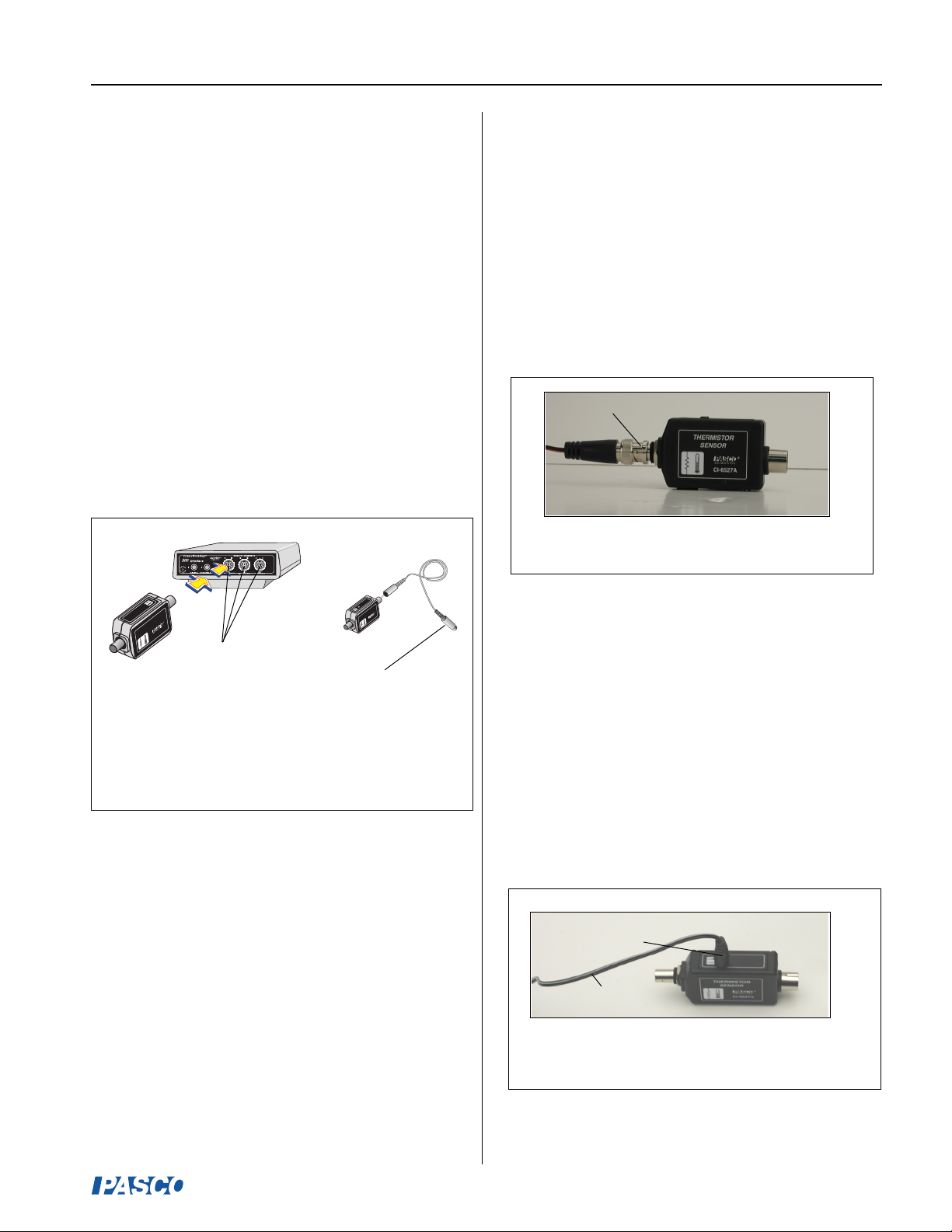
Connecting Cables to the Thermistor
Sensor
Connecting the BNC-to-Dual Banana Plug Cable
to the CI-6527A Thermistor Sensor
The BNC-to-dual banana plug cable (Figure 3a) is
used with 100K thermistors. To plug the BNC cable
into the Thermistor Sensor, insert the BNC metal
connector into the BNC jack on the sensor, and turn
the connector clockwise until it snaps in place.
BNC connector
Figure 3a: Connecting the BNC connector to
the BNC jack on the Thermistor sensor.
R
TO
IS
M
R
SOR
E
N
TH
SE
THERMISTOR
SENSOR
CI-6527
Plug into analog
channel A, B, or C
CI-6527A
to analog channel
on the computer
interface
Figure 2:
Connecting the Thermistor Sensor to the computer
interface (two methods)
Connecting the Stereo-to-Dual Banana Plug Cable
to the CI-6527A Thermistor Sensor
The stereo-to-dual banana plug cable (Figure 3b) is
used with 10K thermistors. PASCO’s more recent
thermal products contain built-in 10K thermistors and
come with a stereo-to-dual banana plug cable. To
order a stereo-to-dual banana plug cable separately,
use part no. 514-08366.
To plug the stereo-to-dual banana plug cable into the
Thermistor Sensor, insert the stereo plug into the stereo
jack on the top of the sensor (Figure 3b).
stereo plug
cable
Figure 3b: Inserting the stereo plug from the dual
banana-stereo plug cable into the Thermistor Sensor
®
3
Page 4
Thermistor Sensor 012-08463B
1
4
3
5
2
6
7
8
R
EL
AT
IV
E
H
U
M
IDIT
Y
%
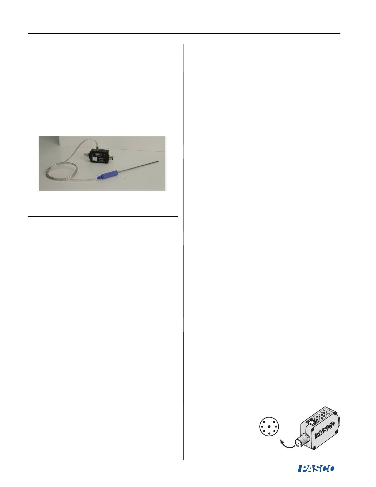
Connecting a Temperature Probe to
the Thermistor Sensor
1. To connect a Temperature Probe to a Thermistor
Sensor, insert the stereo plug on the probe into the
stereo jack on the top of the sensor.
Note: Probes without stereo jacks cannot be connected
to the Thermistor Sensor.
Figure 4: Temperature Probe connected to a
Thermistor Sensor
Sensor Calibration
The Thermistor Sensor is factory calibrated. However,
the unit may be calibrated or have the calibration
verified. Resistors with a known value are required for
calibration. For more information about calibration,
see the DataStudio online help.
Sensor Accuracy and Resolution
The resolution and accuracy of resistance
measurements with the Thermistor Sensor are directly
related to the resolution and accuracy of the
ScienceWorkshop interface used. For example, if the
interface has a resolution and accuracy of ±0.005V,
the resistance measurement will have an accuracy of
36,000 ohms/V times 0.005V or ±180 ohms.
Collecting Data with the Thermistor
Sensor
1. Follow the Procedure under “Connecting the Thermistor
Sensor to a Computer Interface.”
2. Open DataStudio and double click “Create
Experiment.”
3. Click the Setup button to open the Experiment Setup
window.
4. In the Sensors list, scroll to the Thermistor Sensor icon
and drag it to an analog channel on the picture of the
interface (the same channel in which you have the
sensor connected).
5. Double click on the Thermistor icon, click in the
Measurement tab, select a measurement type, and click
OK.
6. Open a Graph display and click the Start button to
begin collecting data.
Sensor Specifications*:
Temperature Range: 10K: -35 to +135ºC
100K: 0 to 100ºC
Resolution: 10K: 0.05ºC
100K: 0.05ºC
Repeatability: 10K: 0.10ºC
100K: 0.10ºC
Accuracy: 10K: 0.5ºC
100K: 0.5ºC
*Note: These specifications are dependent on the quality of
the thermistor used with the CI-6527A Thermistor Sensor
Amplifier. The specifications are typical of the 10K and
100K thermistor used in PASCO temperature probes and
physics apparatus (at 25º
C).
DIN Connector Specifications:
1: analog output, -10 to +10 V
2: analog (-) signal ground
3: no connection
4: +5 VDC power
5: power ground
6: +12 VDC power
7: -12 VDC power
8: no connection
4
®
Page 5

012-08463B Thermistor Sensor
Contacting Technical Support
Before you call the PASCO Technical Support staff,
prepare the following information:
➤ If your problem is with the PASCO apparatus,
note:
- Title and model number (usually listed on the
label);
- Approximate age of apparatus;
- A detailed description of the problem/sequence of
events (in case you can’t call PASCO right away,
you won’t lose valuable data);
- If possible, have the apparatus within reach when
calling to facilitate description of individual parts.
Phone: 1-800-772-8700 (toll-free within the U.S.)
or (916) 786-3800
Fax: (916) 786-3292
E-mail: techsupp@pasco.com
Web: www.pasco.com
➤➤
➤
Note: This instruction sheet was written
➤➤
assuming that the user has a basic familiarity
with DataStudio software. Users can gain
basic skills by working through the tutorial
within the DataStudio software program.
Limited Warranty
PASCO scientific warrants the product to be free
from defects in materials and workmanship for a
period of one year from the date of shipment to the
customer. PASCO will repair or replace, at its option,
any part of the product which is deemed to be
defective in material or workmanship. The warranty
does not cover damage to the product caused by
abuse or improper use. Determination of whether a
product failure is the result of a manufacturing defect
or improper use by the customer shall be made solely
by PASCO scientific. Responsibility for the return of
equipment for warranty repair belongs to the customer.
Equipment must be properly packed to prevent damage
and shipped postage or freight prepaid. (Damage
caused by improper packing of the equipment for
return shipment will not be covered by the warranty.)
Shipping costs for returning the equipment after repair
will be paid by PASCO scientific.
Address: PASCO scientific
10101 Foothills Blvd.
Roseville, CA 95747-7100
Phone: (916) 786-3800
FAX: (916) 786-8905
E-mail: support@pasco.com
Web: www.pasco.com
®
5
 Loading...