

Page 1
Instruction Sheet
for the PASCO
Model CI-6526
Type K Temperature Sensor
Introduction
The PASCO Model CI-6526 Type-K Thermocouple Temperature Sensor is designed
to be used with a PASCO CI computer interface or a PASPORT USB
interface with an Analog Adapter
(PS-2158). A thermocouple works
because junctions between dissimilar metals or alloys in an electrical circuit
give rise to an electromotive force or voltage if they
are at different temperatures. This type of thermocouple is made from a chromel and alumel wire junction.
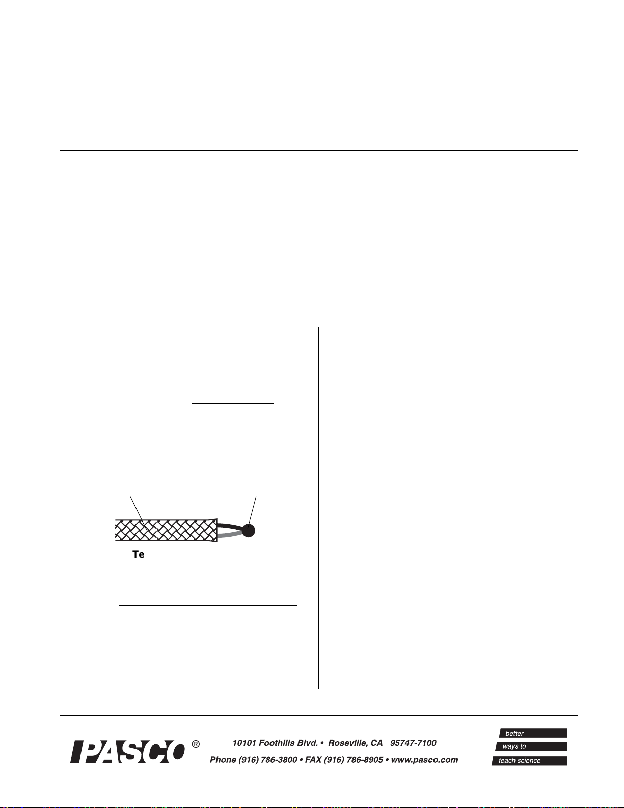
Range
The tip of the 003-05590 Type-K Thermocouple
Probe can withstand temperatures between -180°C
and +1260°C. However, the insulation material that
covers all but the tip of the sensor has a maximum
temperature of +482°C. You can use the sensor to
insulation (maximum
temperature: +482°C)
tip (maximum
temperature: +1260°C)
012-05563D
low zero degrees Celsius. The Type-K Thermocouple
can be used in water and mild chemical solutions; but
it is well suited for dry measurements.
The sensor consists of the Type-K probe (Model
PS-2155) and the sensor electronics box. The sensor
box has a socket made from chromel and alumel that
is mounted very close to the AD595 integrated circuit
(IC). The IC provides the cold junction compensation
as long as the IC temperature is equal to the junction
temperature made by the socket and copper connections. The overall output voltage-to-temperature ratio
is 10 milliVolts per degree Celsius. The output voltage
range is -2.000 (at
-200°C) to +10.000 Volts (at +1,000°C).
Temperature Range of
003-05590 Type-K Thermocouple Probe
measure high temperatures such as those in a candle
flame if you keep the insulated portion of the sensor
out of the flame.
The thermocouple characteristics are fairly linear from
zero degrees Celsius up to the maximum temperature
with an error less than 3°C ± 3% of the reading over
the full range. Note that the error becomes larger be-
Additional Equipment Needed
• Computer Interface such as a PASCO CI interface or a PASPORT USB interface with an Analog Adapter (PS-2158).
Optional Equipment
• The sensor box accepts any Type-K thermocouple, such as the CI-6536 High Temperature
Type-K Thermocouple Probe. The High Temperature Type-K Thermocouple Probe is housed
in a 30.5 cm (12”) inconel metal cover (maximum temperature = +1148°C). Therefore, it can
be used in an open flame or for other high temperature measurements.
Page 2
Type K Temperature Sensor 012-05563D
Operation
Connecting and Using the Sensor
Attach the probe’s two prong connector to the sensor
box at the port marked TYPE K THERMOCOUPLE
PROBE INPUT. The two prong connector can go into
the port only one way because one of the prongs is
wider than the other. Connect the 8-pin DIN plug
from the sensor box to Analog Channel A, B, or C on
the computer interface box.
Touch the bare wire end of the sensor to the object to
be measured or place the sensor end into the solution
to be measured. To prevent damage to the sensor or
the insulating material,
the sensor in a flame or put the insulation in contact
with a heat source above +482°C.
➤ NOTE: IF YOU NEED TO MEASURE A
TEMPERATURE HIGHER THAN +400 °C,
USE THE CI-6536 HIGH TEMPERATURE
TYPE-K THERMOCOUPLE PROBE. (See the
PASCO catalog for more information.)
do not put the insulated part of
put voltage can be converted directly into a temperature. For example, an output voltage of 1.234 Volts
equals a temperature of 123.4 °C.
However, you can calibrate the sensor using a twopoint calibration process.
To calibrate the sensor you will need an accurate thermometer, ice water (0 °C), and boiling water (100 °C).
Calibrating the Sensor Using DataStudio
Assume for this example that the Type-K Thermocouple Temperature Sensor is connected to Analog
Channel A of the interface and that you do not have
any other sensors connected to the interface.
Start the DataStudio program. Select “Setup” from the
DataStudio toolbar. The interface and sensor should
appear in the setup window.
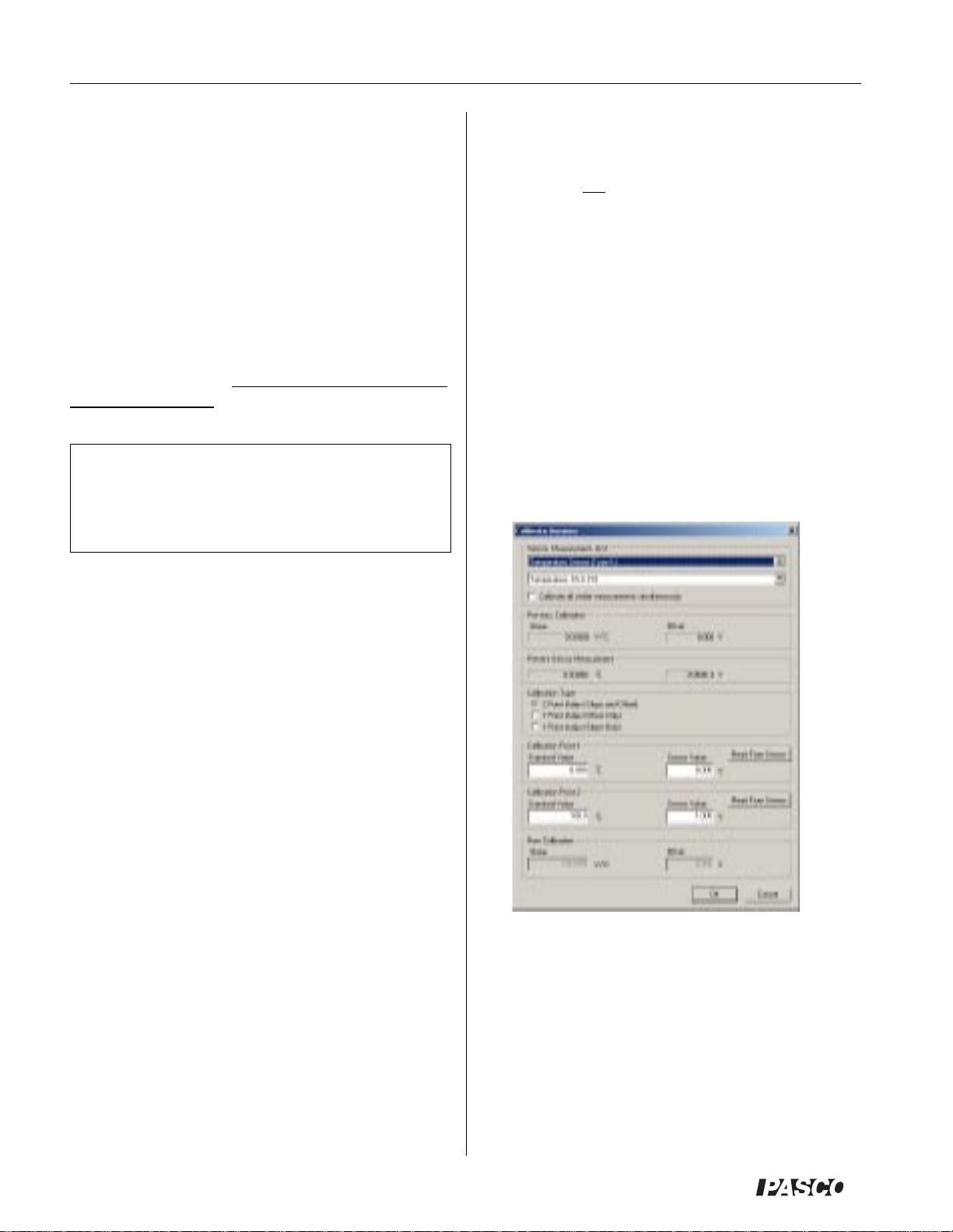
Select “Calibrate Sensors…” from the Experiment
Setup toolbar. Be sure that “2 point (Adjust Slope and
Offset)” is selected under “Calibration Type”.
Using the Sensor in Mild Chemical Solutions
The Type-K Thermocouple is designed to be used in
water and mild chemical solutions when measuring
the temperature of a liquid. The bare wire end of the
thermocouple has been tested for several minutes in
the following chemicals without damage:
acetone sodium hydroxide (lye)
household bleach ethylene glycol butyl ether
isopropyl alcohol ethylene glycol (antifreeze)
naphtha sulfuric acid (battery acid)
vinegar glacial acetic acid
paradichlorobenzene water
• Carefully rinse off any chemicals after each use.
Using the optional Teflon Sensor Cover
A package of ten Teflon Sensor Covers is available
from PASCO (part number CI-6549). See the PASCO
catalog for more information.
Use the optional Teflon FEP sensor cover when the
thermocouple probe must be placed in strong chemical solutions that may damage the probe.
Calibrating the Sensor
The sensor is designed to produce 0.003 V ± 0.005 V
at 0 °C and 10 milliVolts per degree C. Therefore, the
sensor does not need to be calibrated. Instead, the out-
Calibration Point #1: Place the bare wire end of the
thermocouple in the ice water. Also put the thermometer in the ice water. The monitor screen will show the
voltage value produced by the sensor. When the thermometer reading is almost zero, enter the reading in
the “Standard Value” box for Calibration Point 1, then
click the “Read From Sensor” button for Calibration
Point 1.
Calibration Point #2: Place the sensor and thermometer in boiling water. The monitor screen will show the
new voltage produced by the sensor. When the ther-
2
®
Page 3
012-05563D Type K Temperature Sensor
mometer reading reaches a peak, enter the reading in
the “Standard Value” box for Calibration Point 2, then
click the “Read From Sensor” button for Calibration
Point 2. Cilck “OK” at the bottom of the calibratiion
screen and close the Experiment Setup window.
You can save your calibration as a DataStudio docu-
ment by selecting “Save As…” from the File menu.
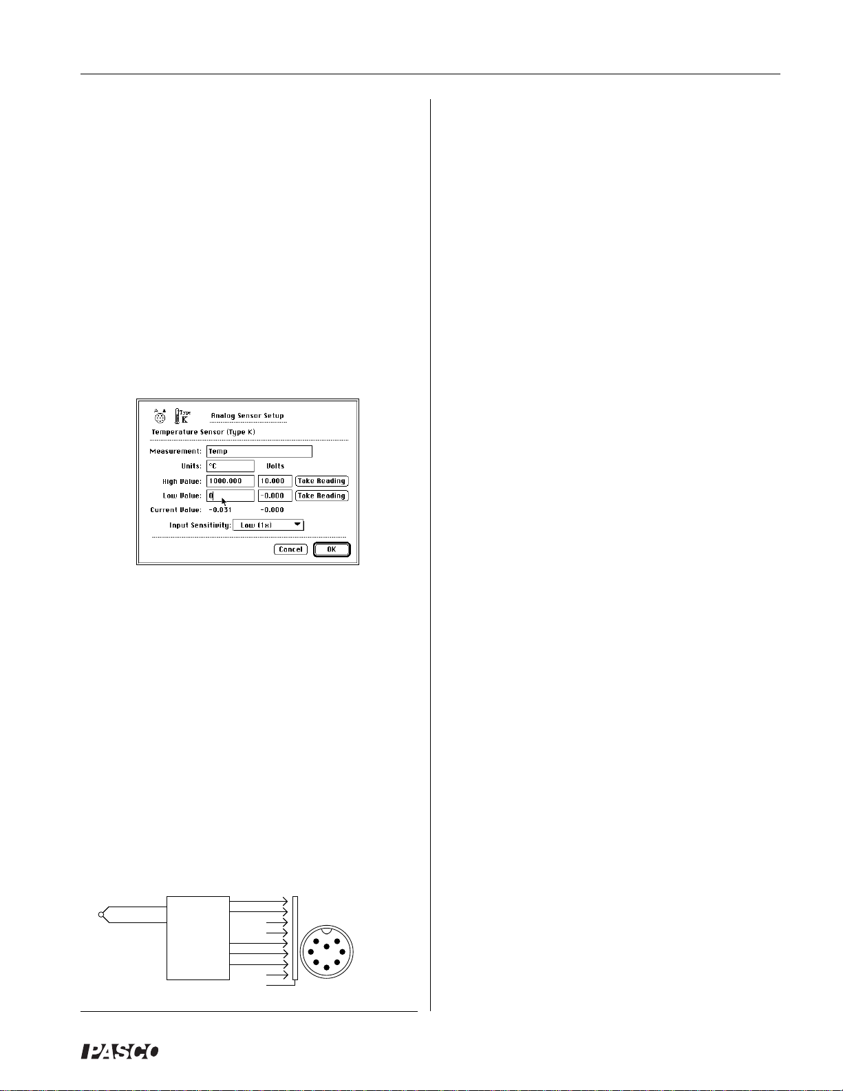
Calibrating the Sensor Using Science Workshop
Start the Science Workshop program. Click-and-drag
the analog sensor plug icon to Analog Channel A. Select “Temperature Sensor (Type-K)” from the list of
analog sensors.
You can save your calibration as a Science Workshop
document by selecting “Save As…” from the File
menu.
Limited Warranty
PASCO scientific warrants this product to be free from
defects in materials and workmanship for a period of
one year from the date of shipment to the customer.
PASCO will repair or replace, at its option, any part of
the product which is deemed to be defective in material or workmanship. This warranty does not cover
damage to the product caused by abuse or improper
use. Determination of whether a product failure is the
result of a manufacturing defect or improper use by
the customer shall be made solely by PASCO scientific. Responsibility for the return of equipment for
warranty repair belongs to the customer. Equipment
must be properly packed to prevent damage and
shipped postage or freight prepaid. (Damage caused
by improper packing of the equipment for return shipment will not be covered by the warranty.) Shipping
costs for returning the equipment, after repair, will be
paid by PASCO scientific.
Calibration Point #1: Place the sensor and thermometer in the ice water. In the Experiment Setup window,
double-click on the Type-K sensor icon to open the
Analog Sensor Setup dialog box.
The dialog box will show the “Current Value” of the
voltage produced by the Type-K sensor. When the
voltage value is almost zero, click on the bottom
“Take Reading” button. Enter the thermometer reading in the box labeled “Low Value:”.
Calibration Point #2: Place the sensor and thermometer in the boiling water. The “Current Value” will
show the new voltage produced by the sensor. When
the voltage value reaches a peak, click on the top
“Take Reading” button. Enter the thermometer reading in the box labeled “High Value:”.
YEL +
2
1
RED -
TYPE K
THERMOCOUPLE
PROBE
CHROMEL
ALUMEL
CI-6526
TEMPERATURE
SENSOR
Schematic Diagram
1
2
3
4
5
6
7
8
S
P1
7
6
1
4
8
2
S
8-PIN DIN PLUG
3
PINS FACING YOU
5
Equipment Return
Should this product have to be returned to PASCO
scientific, for whatever reason, notify PASCO scientific by letter or phone BEFORE returning the product.
Upon notification, the return authorization and shipping instructions will be promptly issued.
➤ NOTE: NO EQUIPMENT WILL BE
ACCEPTED FOR RETURN WITHOUT AN
AUTHORIZATION.
When returning equipment for repair, the units must
be packed properly. Carriers will not accept responsibility for damage caused by improper packing. To be
certain the unit will not be damaged in shipment, observe the following rules:
➀ The carton must be strong enough for the item
shipped.
➁ Make certain there is at least two inches of packing
material between any point on the apparatus and
the inside walls of the carton.
➂ Make certain that the packing material can not shift
in the box, or become compressed, thus letting the
instrument come in contact with the edge of the
box.
®
3
Page 4

Type K Temperature Sensor 012-05563D
4
®
 Loading...