

Page 1
Instruction Manual
Manual No. 012-08088A
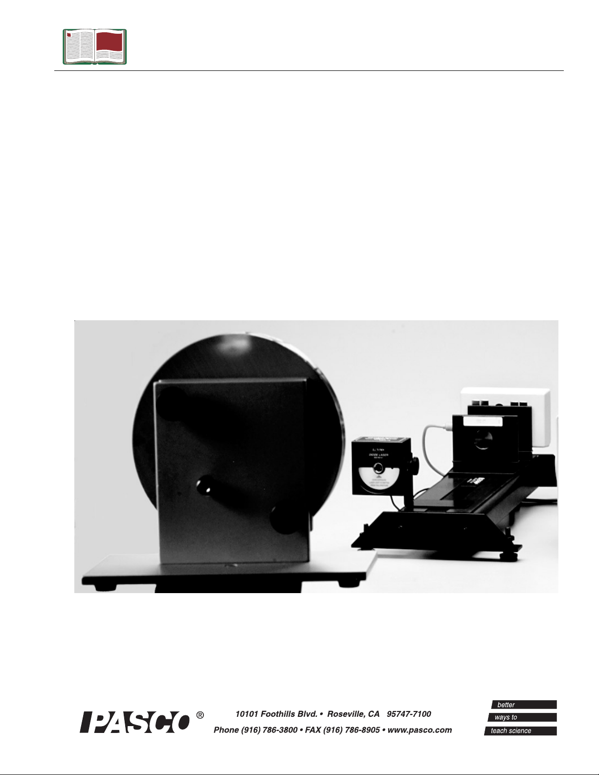
Laser
Speed of Light
Apparatus
Model No. AP-8586
Page 2

Page 3

Apparatus Model No. AP-8586
Table of Contents
Equipment List........................................................ 3-4
Introduction ............................................................. 5
Equipment Setup ..................................................... 5-7
Suggested Experiments ............................................. 7-10
Sample Data............................................................ 11
Appendix A: Specifications............................................ 12
Appendix B: Plotting Data in DataStudio............................. 13
Appendix C: Laser Safety............................................. 14
Appendix D: Technical Support ....................................... 16
Appendix E: Copyright and Warranty Information .................. 17
2
®
Page 4
Model No. AP-8586 Laser Speed of Light System
Laser Speed of Light System
Model No. AP-8586
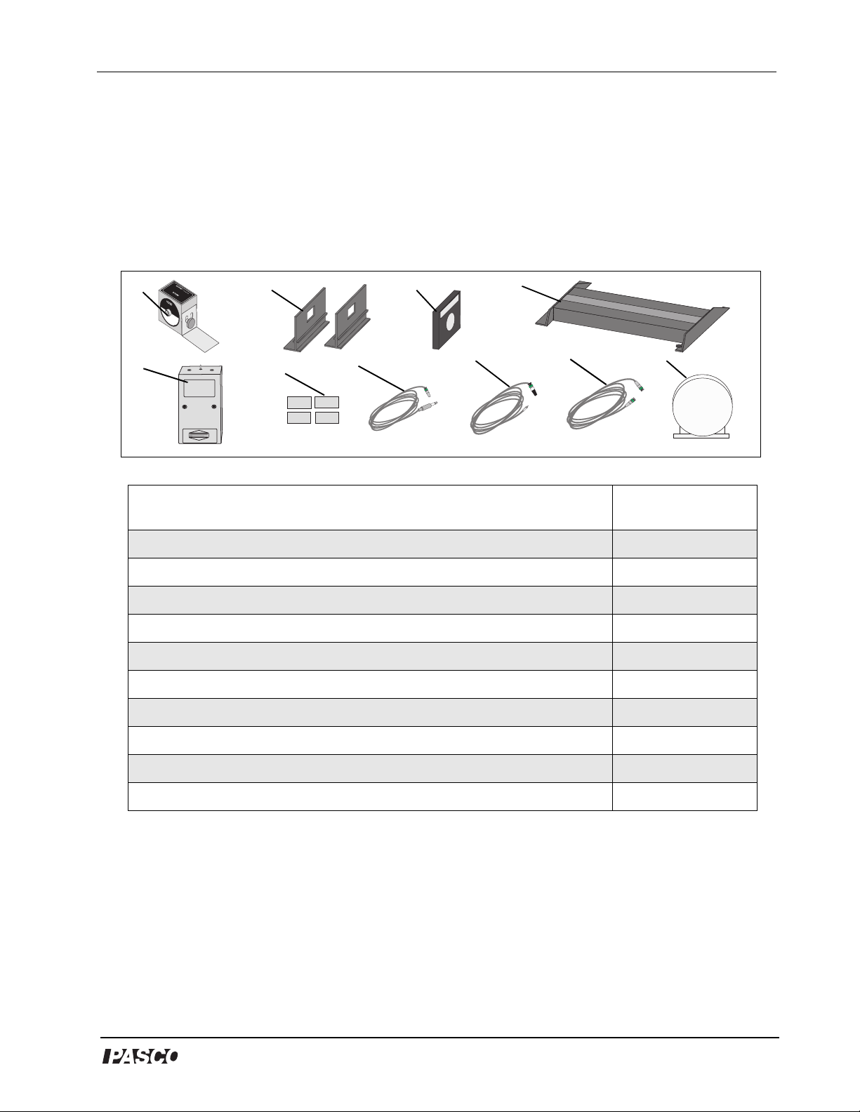
Equipment List
DIODE LASER FOR
OS-8528
OPTICS SYSTEMS
1
D
I
O
D
E
L
0
0
3
A
0
S
6
1
E
5
R
7
A
V
L
O
A
I
S
D
E
E
R
F
X
R
L
P
O
IG
O
M
S
H
U
T
T
R
H
IS
E
I
S
E
A
M
P
IT
E
T
R
E
T
D
U
R
E
2
3
4
5
Metrologic®
45-725
Receiver
DATE 0400
9V
6
7
8
9 10
Included Equipment Replacement
Model Number*
1. Diode Laser with power adapter (1)
2. Component Carrier (2)
3. Lens, +127 mm (1)
4. Laser Alignment Bench (1)
5. Light Receiver (1)
6. Stainless steel pads (4)
7. Cable, coaxial, RCA male to BNC male (1)
8. Cable, coaxial, 3.5 mm phone plug to BNC male (1)
OS-8528A
OS-9107
OS-9134
OS-9172
†See note
OS-9148
†See note
†See note
9. Cable, coaxial, BNC to male (1)
10. Concave Mirror Assembly (1)
*Use Replacement Model Numbers to expedite replacement orders.
†
Contact Pasco for replacement of items (see page 15 for contact information).
®
†See note
003-02226
3
Page 5
Laser Speed of Light System Model No. AP-8586
Equipment List (Continued)
Additional Equipment Required (for experiments) Replacement
Model Number*
Function Generator, wide range
Oscilloscope, 60 MHz
Tripod
Tape measure
Tape (for marking floor)
Plumb bob (for indicating mirror position)
Laser Safety Goggles or protective shields (recommended, but
not required)
**
SB-9549A
NA
NA
SE-8172A
NA
NA
NA
NA = not available from PASCO scientific
** See Appendix C: Laser Safety for more information about safety goggles.
About the Equipment:
Diode Laser - The diode laser emits an intense, narrowly-focused beam of light. In this
experiment, the diode laser is powered by a function generator, which modulates the light
intensity at approximately 3 MHz. The laser is equipped with adjustment screws for
precisely aiming the light at the mirror.
Concave mirror - The concave surface of the mirror helps to focus the light as it is
reflected. The mirror is also equipped with adjustment screws for aiming the light back to the
receiver.
Light Receiver - The receiver is designed for receiving audio and video signals transmitted
via modulated light. Since the light receiver is sensitive to very high-frequency modulation,
it is ideally suited to the experiment in this manual. There are two sensitive elements on the
receiver; in this experiment, you will use only the one labeled “Video.”
+127 mm Lens - The lens is used to focus the light onto the sensitive element of the
receiver.
4
®
Page 6
Model No. AP-8586 Laser Speed of Light System
s
d
Introduction
The velocity of light in free space is an important and intriguing
constant of nature. Whether the light comes from a laser on a desktop
or from a star that is hurling away at fantastic speeds, the velocity of
light will yield the same constant value. In more precise terminology,
the velocity of light is independent of the relative velocities of the light
source and the observer.
As Einstein first presented in his Special Theory of Relativity, the
speed of light is critically important in some surprising ways:
1. The velocity of light establishes an upper limit to the velocity that
may be imparted to any object.
2. Objects moving near the velocity of light follow a set of physical
laws drastically different, not only from Newton’s Laws, but from
the basic assumptions of human intuition.
It is not surprising that a great deal of time and effort has been invested
in measuring the speed of light. Some of the most accurate
measurements were made by Albert Michelson between 1926 and
1929. Michelson measured the velocity of light in air to be 2.99712 x
8
m/sec. From this result, he deduced the velocity in free space to be
10
2.99796 x 10⁸ m/sec.
Equipment Setup
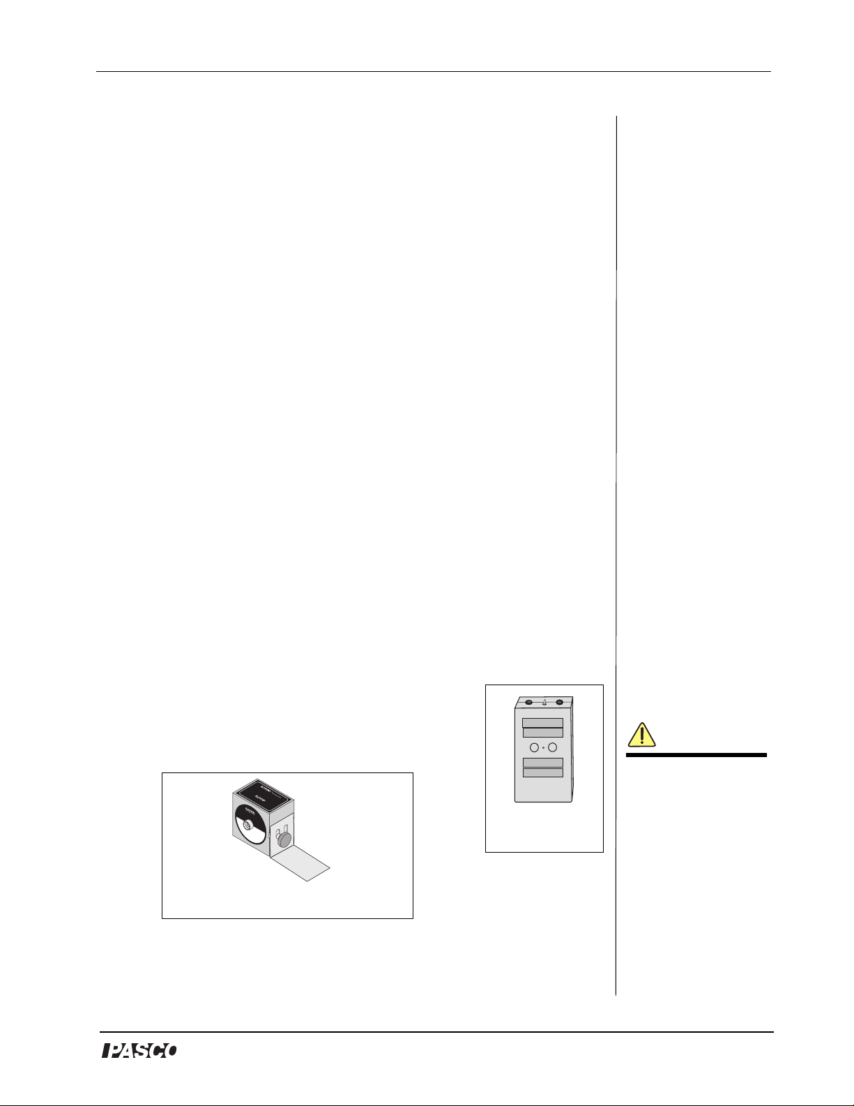
1. Stick four stainless steel strips to the front of the
receiver (Figure 1).
2. Mount the laser on its L-shaped bracket, with the
bracket bent away from the laser (Figure 2).
DIODE LASER FOR
OS-8528
OPTICS SYSTEMS
DIODE LASER
003-06157
AVOID EXPOSURE
LASER LIGHT IS EMITTED
FROM THIS APERTURE
Figure 2: Laser with bracket
Figure 1:
Receiver
WARNING: Before
setting up your equipment,
please inform your student
of the hazards of lasers an
enforce appropriate safety
precautions in your
classroom. For more
information, see Appendix
C: Laser Safety in this
manual.
®
5
Page 7

Laser Speed of Light System Model No. AP-8586
3. Arrange the laser, lens, receiver and two component carriers on the
laser alignment bench (Figure 3).
R
E
S
7
LA
15
E
6
D
0
3
0
IO
0
D
E
R
D
U
E
S
T
T
O
I
P
E
M
X
R
E
E
U
T
IS
ID
R
T
O
E
H
V
P
A
A
IG
S
L
I
R
H
E
T
S
M
A
L
O
R
F
Figure 3: Aligning the lens, carriers,
and receiver with the laser
4. Place the alignment bench on a horizontal surface. You will need
10 to 20 m of clear space in front of the laser.
5. Mount the mirror on the tripod and place it a few meters in front of
the laser. Adjust the tripod so that the mirror is at the same height
as the laser. (see Figure 3 for the setup.)
6. Mark the position of the mirror on the floor with tape. (Attach a
plumb bob to the tripod, so that you mark a point directly below the
mirror.
7. With tape, mark the floor at regular intervals to about 10-20 meters
from the laser. Allow for at least 10 different intervals within the
allotted space.
8. Using the BNC male-to-male cable, connect the TTL output of the
function generator to channel 1 of the oscilloscope.
9. Using the RCA male-to-BNC male cable, connect the “Video”
output of the receiver to channel 2 of the oscilloscope.
10. Using the phone plug-to-BNC male cable, connect the power jack
of the laser to the output of the function generator.
11. Set the function generator for a square wave, and press the DC
Offset button. Turn the Output and DC Offset knobs completely
counterclockwise.
12. Turn the laser switch to the “on” position.
13. On the function generator, turn up the DC Offset knob until you
see laser light. Do not look directly into the laser light!
6
®
Page 8

Model No. AP-8586 Laser Speed of Light System
WARNING: Never look directly at the laser light source or
reflected light, such as from a mirror. Although the laser used
in this experiment is of low power, looking directly into the
laser light source or its reflected light from a mirror could cause severe
eye injuries or burns. To avoid eye injury, do not look directly into the
beam of the laser and wear laser protective goggles. When aligning the
laser, use the alignment marker. For more information about laser
safety, see Appendix C of this manual.
14. Align the laser, mirror, lens and receiver so that the laser beam is
focused onto the “Video” sensing element of the receiver.
15. Set the scope to dual trace:
a) Set channel 1 to 1v/div., DC.
b) Set channel 2 to 1 v/div., AC.
c) Set the trigger to channel 1.
d) Set the trigger level to about 2.5 volts.
e) Set the time base to 50 ns/div.
16. Adjust the alignment of the laser, mirror, lens, and receiver to
maximize the sine wave signal on channel 2.
17. Adjust the DC offset and amplitude of the function generator to
maximize the signal on channel 2.
Experiment 1: Modulated Laser Method
for Measuring the Speed of Light
In this experiment, you will measure the speed of light using a laser
modulated at a very high frequency and an oscilloscope. You will
measure the time, , that elapses while the light signal travels a
known distance, , and you will calculate the speed of light, which is
defined as .
∆d ∆t⁄
The light signal, originating at the laser, will travel to the mirror and
back to the light receiver. You will vary by moving the mirror and
measuring the corresponding effect on with the oscilloscope.
∆t
∆d
∆d
∆t
WARNING: Always
inform your students of
the hazards of lasers
and enforce appropriate
safety precautions in
your classroom. For
more information, see
Appendix C: Laser
Safety in this manual.
It is not necessary (or practical) to measure the actual elapsed time,
since we are only interested in how changes as varies.
Therefore, you will actually measure an elapsed time relative to an
®
∆t
∆d
∆t′
7
Page 9

Laser Speed of Light System Model No. AP-8586
∆d′
arbitrary (but constant) baseline. This elapsed time can be expressed
mathematically as:
∆t′∆tt
+=
(equation 1)
k
where tk is an unknown constant. For the same reason, you can also
measure instead of where
(equation 2)
d′
∆d′∆dd
+=
The equation of a line fitted to a plot of vs. is
∆d′ c∆t′=
(equation 3)
∆d
k
∆t′
where c represents the slope of the line. The combinations of
equations 1, 2, and 3 yields
∆dc∆tK+=
(equation 4)
where K is another arbitrary constant. In equation 4, it is evident that
the slope, c, equals , which is the speed of light.
∆d ∆t⁄
Procedure
1. Adjust the alignments of the laser and mirror and the positions of the
lens and receiver to maximize the signal. (Adjust the receiver up,
down, left and right on the carrier, but do not change the position of
the carrier on the bench.)
2. On the oscilloscope, adjust the scale and vertical position of the
signal to maximize the signal trace. Do not change the horizontal
position of the trace.
3. Record the position of the mirror (relative to its initial position) and
the phase of the signal in Table 1a. If your oscilloscope is equipped
with cursors, use them to measure the phase. Otherwise, estimate
the phase to 1/2 of the smallest division on the time scale.
4. Move the mirror back to the next mark and repeat steps 1 through 4.
8
®
Page 10

Model No. AP-8586 Laser Speed of Light System
Tabl e 1a
Mirror
Position
(m)
Phase
(s)
Analysis
Plot vs. . (Remember that is two times the mirror
∆t′
∆d′∆d′
position. The slope of the best-fit line is the speed of light.
Note: You can plot your data and obtain the best-fit line using
DataStudio. For instructions, see Appendix B of this manual.
®
9
Page 11

Laser Speed of Light System Model No. AP-8586
Sample Data
Table 1: Path Length vs. Phase
Path Length vs. Phase Data
10
®
Page 12

Model No. AP-8586 Laser Speed of Light System
Appendix A: Specifications
Component Description
Diode Laser 1 mw, 650 nm
Component Carrier 6.3 cm (height) x 7.6 cm (length);
3.8 cm x 7.5 cm (base)
Lens 127 mm
Laser Alighment Bench 38.8 cm length
Metrologic Light Receiver 10.2 cm x 6.2 cm x 4.2 cm; two
channel output (one audio, one
video), dual light sensors, 9 VDC
Stainless steel pads 0.97 x 4.5 cm, rectangular,
stainless steel
Cable, coaxial, RCA male to
BNC male
Cable, coaxial, 3.5 mm phone
plug to BNC male
Cable, coaxial, BNC to male 183 +/- 2.5 cm length
Concave Mirror Assembly 13.5 meters
183 +/- 2.5 cm length
183 +/- 2.5 cm length
®
11
Page 13

Laser Speed of Light System Model No. AP-8586
Appendix B: Plotting Data in DataStudio
The following instructions are provided for new users or those
unfamiliar with DataStudio. The following instructions explain how to
create an x-y graph and/or calculate statistics on previously collected
data.
1. Open DataStudio. When the Welcome to DataStudio window opens,
select “Enter Data.” An editable table and Graph display open.
2. On the main toolbar, click the Summary button.
3. In the Data list, double click on the data icon to open the Data
Properties dialog.
4. In the Data Properties dialog, do the following:
a) Enter a name for your experiment in the Name box.
b) Click on the X tab and enter the variable name “Phase” to label
the x axis. Enter the units for phase (ns or s).
c) Click on the Y tab and enter the variable name “Path Length” to
label the y axis. Enter the units for length (m). Click OK.
5. In the Editable data table, enter your values for phase and path
length. The data values automatically plot in the graph to the right.
6. On the graph toolbar, click the Curve Fit button and select “Linear
Fit.” Slope, intercept, correlation, and standard deviation values
appear in a box on your display.
12
®
Page 14

Model No. AP-8586 Laser Speed of Light System
Appendix C: Laser Safety
The OS-8528 is a low power, Class 2 laser. When Class 2 lasers are
used in accordance with Occupational Health and Safety
Administration (OSHA) standards, Class 2 lasers are not harmful.
However, when appropriate safety precautions are not taken, Class 2
lasers can cause permanent, irreversible damage to the eyes, skin, and
other body tissues. As an instructor, you should always inform your
students of the hazards of lasers and the necessary preventative, safety
measures.
PASCO cannot be held liable for negligent use in the classroom. As a
courtesty, we are providing you with the following laser safety
instructions. These reminders are not a comprehensive list of all
possible safety measures or hazards. For more information, see the
OSHA web site (http://www.osha.gov). Also see http://
www.safetymanual.com or www.laserinstitute.org
Safety Reminders:
• Never look directly into the laser or at any reflection from the laser at
eye level (see figure 5 below).
Figure 5
DO NOT DO THIS!
• Keep your eyes at least 1 foot above the light source. (see Figure 6).
Figure 6
OPTICS SYSTEMS
D
IO
D
E
L
003-0615
A
VOID EXPOSURE
LASER LIG
F
ROM THIS APERTURE
HT IS EMITTED
DIODE LASER FOR
A
S
E
R
7
D
O
P
T
IC
D
IO
D
E
LA
0
03-
06
AVOID EXPOS
LA
SER LIG
FROM TH
HT IS EM
IS APERTUR
OS-8528
laser light source
IO
OS-8528
D
E
L
A
S
E
R
S
F
S
O
Y
R
S
T
E
M
S
SE
157
R
URE
ITTED
E
emitted rays
®
13
Page 15

Laser Speed of Light System Model No. AP-8586
•Do not place your hand, finger, or any other part of your body directly
on the laser. Lasers can burn the skin and damage tissue.
• Do not point a laser at your own eye, through glass, mirrors or
transparent objects in your surroundings, or at the eyes of other
individuals.
• Never remove any of the covering or components of the AP-8586
Diode Laser. If the laser is defective, return the defective laser
immediately to PASCO scientific.
• If you are uncomfortable or unsure about working around lasers,
wear protective laser goggles or spectacles.
About Laser Protective Eyewear
The eyewear must be designed for use with lasers and meet OSHA
standards specific to the type and class of laser you are using. You can
tell if the type of goggle or spectacle you are using meets laser
standards by looking at the insignia on the side of the frame. Any type
of plastic chemical protective goggle will not suffice. Also, you need
to select protective eyewear with the correct filter for the wavelength
range of the laser (For a Class 2 laser, you need a 400-780 nm filter.)
Example: Laser goggles designed to protect for Class 1 lasers do not
provide maximum protection when using Class 2 lasers. For more
information, see the OSHA web site (www.osha.gov).
Laser Injuries
Severe corneal injuries or eye burns may or may not present with pain
at the surface of the eye. In retinal injuries, the individual may see red
spots, or have blurred vision or altered color perception.
Less severe injuries may not show up immediately and are more
hazardous when they occur repetitively.
If you believe you have a laser injury, report the injury immediately to
your instructor/supervisor, school health department and/or safety
officer. If necessary, go to an emergency health facility or contact a
medical doctor or opthalmologist.
14
®
Page 16

Model No. AP-8586 Laser Speed of Light System
Appendix D: Technical Support
For assistance with the AP-8586 or any other PASCO products,
contact PASCO as follows:
Address: PASCO scientific
10101 Foothills Blvd.
Roseville, CA 95747-7100
Phone: 1-800-772-8700 or (916) 786-3800
FAX: (916) 786-3292
Web: www.pasco.com
Email: techsupp@pasco.com
®
15
Page 17

Laser Speed of Light System Model No. AP-8586
Appendix E: Copyright and Warranty
Information
Copyright Notice
The PASCO scientific 012-08088A Laser Speed of Light Apparatus
Manual is copyrighted and all rights reserved. However, permission is
granted to non-profit educational institutions for reproduction of any
part of the 012-08088A Laser Speed of Light Apparatus Manual,
providing the reproductions are used only for their laboratories and are
not sold for profit. Reproduction under any other circumstances,
without the written consent of PASCO scientific, is prohibited.
Limited Warranty
PASCO scientific warrants the product to be free from defects in
materials and workmanship for a period of one year from the date of
shipment to the customer. PASCO will repair or replace, at its option,
any part of the product which is deemed to be defective in material or
workmanship. The warranty does not cover damage to the product
caused by abuse or improper use. Determination of whether a product
failure is the result of a manufacturing defect or improper use by the
customer shall be made solely by PASCO scientific. Responsibility for
the return of equipment for warranty repair belongs to the customer.
Equipment must be properly packed to prevent damage and shipped
postage or freight prepaid. (Damage caused by improper packing of
the equipment for return shipment will not be covered by the
warranty.) Shipping costs for returning the equipment after repair will
be paid by PASCO scientific.
16
®
Page 18

 Loading...