

Page 1
®
Instruction Manual
A
B
C
D
E
F
F
Stress-Str ain
platform
Lever arm
Coupon
clamps
Plunger
Pivot
Force Sensor
post
Belt
Crank
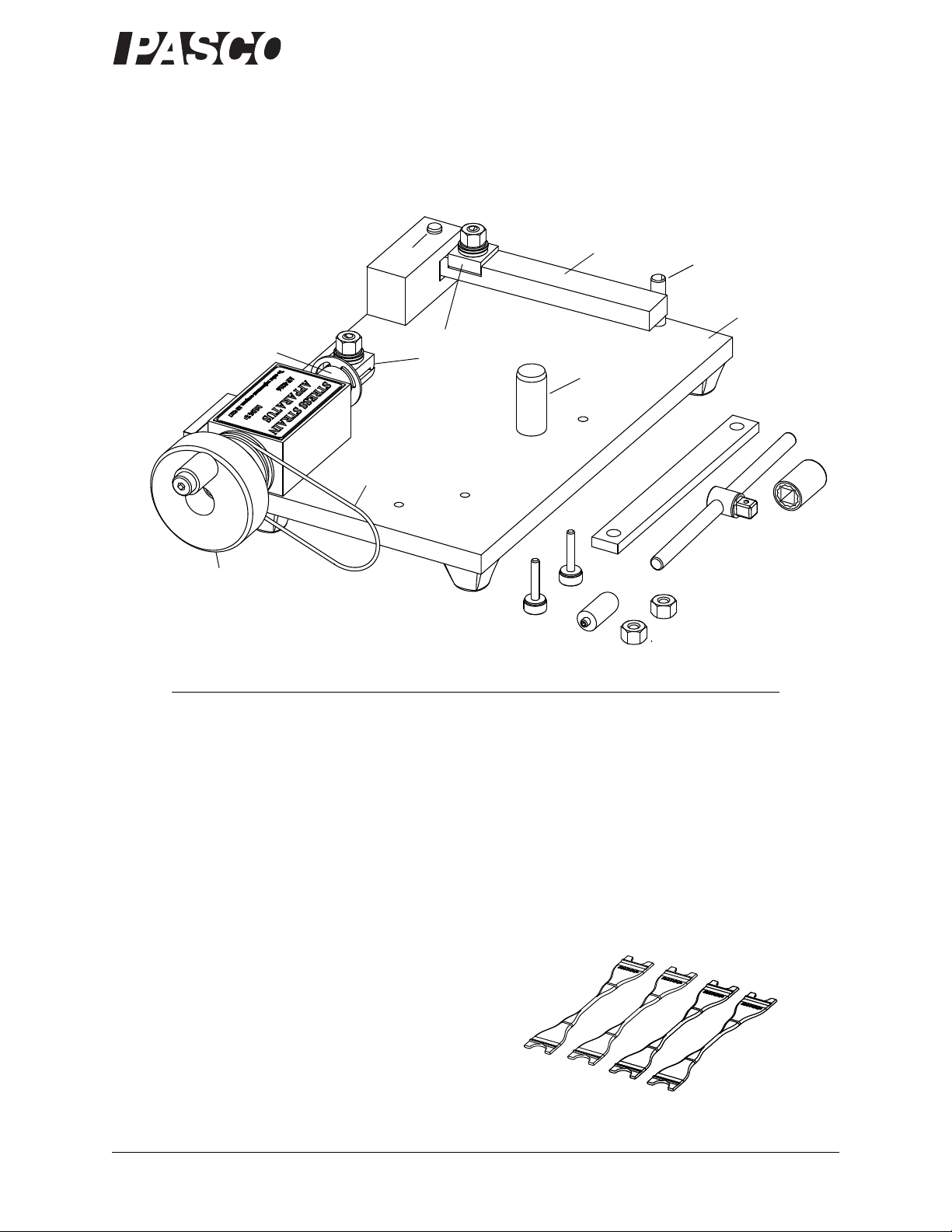
Fig. 1: Included Equipment
Lever arm
stop
Fig. 2: AP-8222 Plastic Test Coupons
*012-13282*
Stress/Strain Apparatus
AP-8214A
012-13282A
Included Equipment
A. AP-8221 Stress/Strain Apparatus without Coupons
B. Thumbscrews for Rotary Motion Sensor, 2 pieces
C. Attachment for force sensor
D. Replacement hex nut, 2 pieces
E. Calibration bar
F. Tee handle plus Socket, 3/8 inch
• PASCO Experiment Setup CD-ROM and Storage Box (not shown)
AP-8222 Plastic Test Coupons: 4 color-coded samples, 10 pieces per sample
• high impact polystyrene (HIPS)
• nylon 6 (15% glass fiber reinforced)
• acrylonitrile butadiene styrene (ABS)
• polypropylene (PP)
• The plastic coupons are attached to a rectangular plas-
tic rail called a ‘sprue’. Use scissors or a knife to cut the
coupon from the sprue.
800-772-8700 www.pasco.com
Page 2
®
Stress/Strain Apparatus 012-13282A Introduction
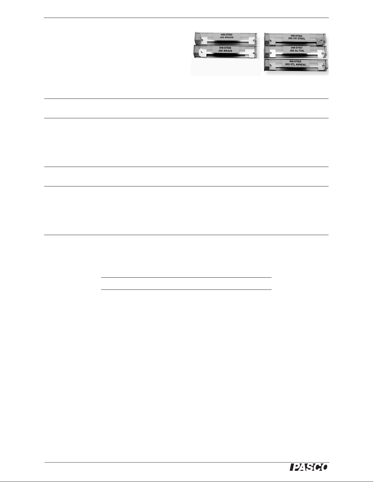
Fig. 3: AP-8223 Metal Test Coupons
AP-8223 Metal Test Coupons: 5 samples, 10 pieces
per sample (sample containers labeled with
thickness in inches)
• cold-rolled steel 0.003”
• annealed steel 0.003”
• aluminum 0.003”
• brass (thick) 0.005”
• brass (thin) 0.003”
Note: The metal coupons are packaged in plastic containers to prevent bending or creasing of the coupons.
Additional Equipment Required for Use with
ScienceWorkshop
Sensors Part Number
ScienceWorkshop Interface See PASCO catalog or www.pasco.com
DataStudio
1
See PASCO catalog or www.pasco.com
Economy Force Sensor CI-6746
Rotary Motion Sensor CI-6538
Additional Equipment Required for Use with
PASPORT Sensors Part Number
PASPORT Interface
DataStudio
1
2
See PASCO catalog or www.pasco.com
See PASCO catalog or www.pasco.com
Force Sensor PS-2104
Rotary Motion Sensor PS-2120
1
DataStudio 1.8 or later recommended. Visit www.pasco.com to download the latest version. DataStudio Lite, the free version, is
sufficient for use with the experiment set-up files on the included CD.
2
The two sensors used on the Apparatus require a single multi-port interface such as the Xplorer GLX (PS-2002) or PowerLink
(PS-2001), or two single-port interfaces such as the USB Link (PS-2100) or Xplorer (PS-2000).
Recommended Equipment Part Number
Replacement Test Coupons* AP-8217A
Digital Calipers SE-8710
*The AP-8217A Replacement Test Coupons include all of the AP-8222 plastic and AP-8223 metal test coupons.
Introduction
The PASCO AP-8214A Stress/Strain Apparatus illustrates the relationship between stress and strain for various materials. The apparatus stretches a test coupon (and breaks it in some cases) while measuring the amount of stretch and
force experienced by the test coupon. Data acquisition software can be used to generate a plot of force versus displacement and also a plot of stress versus strain.
The Stress/Strain Apparatus requires a ScienceWorkshop or PASPORT interface, DataStudio software, a Rotary
Motion Sensor (RMS), and a Force S ens or. Incl uded with th e appar atu s ar e four types of metal test coupons an d fo ur
types of plastic test coupons. Also included are a tee handle with a socket that fits the hex nuts on the coupon clamps,
a bar for calibrating the apparatus, and spare hex nuts for the coupon clamps.
This manual includes instructions for setting up the Stress/Strain Apparatus with ScienceWorkshop or P ASPORT sen-
sors. It also describes how to do the calibration and the data collection using the DataStudio set-up files that are on the
included PASCO Experiment Setup CD-ROM. The CD-ROM has a folder labeled “AP-8214 SETUP” that contains
two DataStudio configuration (set-up) files, two DataStudio workbook files, and a sample data file.
2
Page 3
®
Model No. AP-8214A 012-13282A Introduction
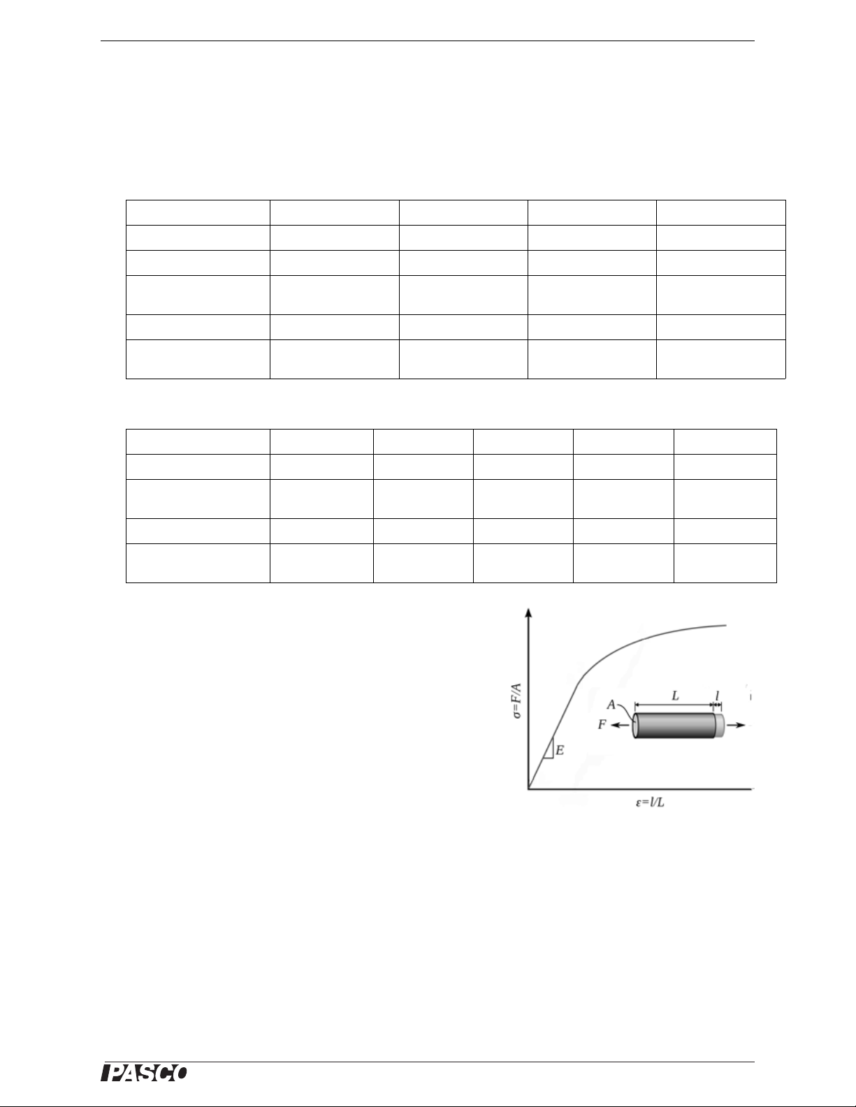
Fig. 4: Stress-Strain curve
Test Coupon Specifications
The data below are intended as a general guide only and do not necessarily represent results that may be obtained.
The units for tensile strength and modulus of elasticity are megapascals (MPa or 10
6
N/m2) and pounds per square
inch (psi).
AP-8222 Plastic Test Coupons
Item HIPS nylon 6 (+ 15% glass) ABS polypropylene
Color code orange black blue white
Cross-sectional area 2.482 mm
Tensile strength 23 MPa/
3410 psi
Tensile elongation 40% 2.5% 20% 9%
Modulus of elasticity 2000 MPa/
280000 psi
2
2.482 mm
98 MPa/
14000 psi
2900 MPa/
420000 psi
2
2.482 mm
47 MPa/
6800 psi
2300 MPa/
380000 psi
2
2.482 mm
34 MPa/
4900 psi
1900 MPa/
239000 psi
2
AP-8223 Metal Test Coupons
Item cold-rolled steel annealed steel aluminum brass (thin) brass (thick)
Cross-sectional area 0.303 mm
Tensile strength 620 MPa/
90,000 psi
2
0.303 mm
300 MPa/
44,000 psi
2
0.303 mm
145 MPa/
21,000 psi
2
0.303 mm
430 MPa/
44,000 psi
2
0.506 mm
430 MPa/
44,000 psi
2
Tensile elongation none 42-45% 6% 25% 25%
Modulus of elasticity 200,000 MPa/
29,000,000 psi
200,000 MPa/
29,000,000 psi
69,000 MPa/
10,000,000 psi
117,000 MPa/
17,000,000 psi
Theory.
A stress-strain tensile test measures the amount of stretching force
applied to a sample of material, and the amount of stretch of a material. Stress (σ) is the ratio of force (F) per unit of cross-sectional area
(A). Strain (ε) is the ratio of the change of length (l) compared to the
original length (L). A stress-strain curve is a graphical representation
of the load applied and the deformation of the sample. The curve varies from material to material.
Ductile materials like metal have a linear stress-strain relationship up
to a point. The slope of the linear part of the stress-strain curve is
called “Young’s modulus” or the modulus of elasticity (E) and is a
property used to characterize materials.
117,000 MPa/
17,000,000 psi
3
Page 4
®
Stress/Strain Apparatus 012-13282A Equipment Set-up
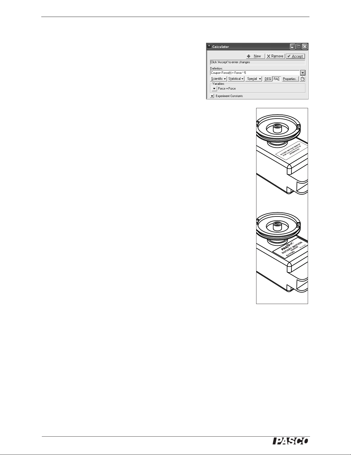
Fig. 5: Force calculation
ScienceWorkshop
PASPORT
Fig. 6: Three-step
pulley on the
“clockwise positive”
side of RMS
About the Apparatus
The lever arm on the Stress/Strain Apparatus is a Class III lever that
transmits the applied force to the Force Sensor. The length of the
lever arm from the pivot to the Force Sensor attachment is five times
longer than the length of the lever arm from the pivot to the coupon
clamp that is part of the lever arm. The force applied to the test coupon is five times more than the force measured by the Force Sensor.
Therefore, each DataStudio set-up file uses a calculation that multiplies the measured force by five.
Equipment Set-up
1. Attach the Rotary Motion Sensor to the apparatus platform.
• Remove the rod clamp from the RMS.
• Place the three-step pulley (Item 6) onto the shaft of the RMS with the largest pulley on the outside. The three-step pulley should be on the “clockwise positive” side
of the RMS as shown in the figure.
• Place the RMS on the platform as illustrated below. Use the two thumbscrews to
fasten the RMS to the platform from beneath.
• Seat the belt (Item 7)on the middle step of the three-step pulley and the groove on
the crankshaft.
2. Attach the Force Sensor to the apparatus platform.
• Remove the hook from the Force Sensor and replace it with the force sensor
attachment (Item 3, included).
• Place the Force Sensor on the apparatus platform by putting the support rod
mounting hole onto the Force Sensor post.
• Insert the long thumbscrew supplied with the Force Sensor through the hole on the
Force Sensor marked “Cart” and screw it into the threaded hole in the apparatus
platform.
• Tighten the setscrew (Item 4) in the support rod mount of the Force Sensor.
3. Clamp down the apparatus (optional). Use a large C-clamp to clamp the Appa-
ratus Platform to the edge of your bench or table. One side of the platform has
three feet. In order to avoid bending the platform, position the clamp directly over
the center foot.
4
Page 5

®
Model No. AP-8214A 012-13282A Equipment Set-up
1. Rotary Motion Sensor (RMS)
2. Force Sensor
3. Force Sensor attachment
4. Force Sensor setscrew
5. Stress Strain platform
6. 3-step pulley
7. belt
8. groove
9. coupon clamps
10. lever arm
11. thumbscrew
12. coupon
Fig. 7: Equipment Set-up
1
2
3
4
5
6
7
8
9
9
10
11
12
Fig. 8: DataStudio files
Fig. 9: Stress Strain PS.ds DataStudio configuration file
4. Plug the sensors into the
interface.
• ScienceWorkshop interface: Connect the Force
Sensor to Channel A.
Connect the yellow plug
of the RMS to Channel 1
and the black plug to
Channel 2.
• PASPORT interface: Con-
nect the Force Sensor and
the RMS to a multi-port
interface or two single-port interfaces.
Prepare DataStudio
The included CD-ROM has a folder labeled “AP-8214 SETUP” that conta ins two Data Studio configuration (se t-up)
files, two DataStudio workbook files, and a sample data file.
Start DataStudi o and open the configu ration file Stress Strain SW.ds (for ScienceWorkshop) or Stress Strain PS.ds (for
PASPORT) located on the included CD-ROM. Each configuration file has Graph displays, Digits displays and several calculations.
5
Page 6

®
Stress/Strain Apparatus 012-13282A Equipment Set-up
Fig. 10: Remove clamps (side view)
nut
flat washer
convex washer
concave washer
clamp top
spring
bolt
lever arm
plunger
calibration
bar
lever arm
force sensor
attachment
Fig. 11
gap
lever arm stop
Fig. 12: Displacement(t) vs Coupling Force(t)
calibration data
Apparatus Calibration
As you turn the crank during the experiment, force will be applied to the test coupon causing it to stretch. However,
this applied force will also cause the apparatus platform and the Force Sensor to bend slightly. The displacement
recorded by the RMS will be the combination of the coupon stretching and the rest of the apparatus b e ndin g.
Regardless of how much the coupon stretches, the deformation of the rest of the apparatus is constant for a given
force. You can measure this deformation directly by using the calibration bar (which does not stretch significantly) in
place of a coupon. In the resulting Displacement versus Force graph, the displacement is due only to bending of the
apparatus. Later, you will subt ract this calibration plot from a similar plo t made with a cou pon , in which the dis placement results from both bending of the apparatus and stretching of the coupon. The difference will be a plot in which
the displacement is due only to stretching of the coupon.
Follow these steps to acquire calibration data:
1. Install the Calibr ation Bar
• For each coupon clamp, remove the nut, washers, clamp top,
and spring from the bolt (Figure 10).
• Turn the crank to adjust the position of the bolts if needed and
slip the calibration bar over the bolts. Do not replace the cou pon
clamp parts when using the calibration bar.
2. Place the lever arm in the starting position. Turn the crank
counter-clockwise and pull the lever arm away from the Force
Sensor (Figure 11) .
3. Collect Displacement versus Force Data.
• Press the Tare or Zero button on the Force Sensor.
• Click the Start button.
• Turn the crank clockwise. Starting just before
the lever arm comes into contact with the Force
Sensor attachment, turn the crank very slowly.
DataStudio will start recording when the force
applied to the coupon reaches 2.5 N, or 1% of
maximum (as shown in the “% Max Force” digits display).
• Continue to turn the crank until the force reaches
100% of maximum. At this point, DataStudio
will stop recording automatically.
6
Page 7

®
Model No. AP-8214A 012-13282A DataStudio Set-up
* To rename a data run, click the run name (e.g. “Run #1”) where it appears in the Data List. Wait about 1 second
then click it again. Enter the new name. A dialog box will appear. Select Yes. (If a window titled “Data Properties”
appears, you didn't wait long enough after the first click; close that window and try again.)
Fig. 13: Define Variables in Calculator
• Change the name of the data run (Run #1) containing the calibration data to “Cal”.*
DataStudio Set-up
1. Prepare the calculation for “Calibrated Displacement(F)”. In the Calculator window, select the “Cali-
brated Displacement(F)” calculation and define the variables.
• Drag “Displacement(t) vs Coupon Force(t) (mm)” to “Please define variable ‘Displacement’.” (Figure 13)
• Drag “Cal” to “Please define variable ‘Cal’” in the Calculator window. (DataStudio will display a warning
box stating that a “single run is selected”. Click the Yes button in that box.)
2. Prepar e the calculation for “S tr ess(F)”. In the Calc ulator window,
select the defined function “Stress(F) = Force/Area”. In the Variables section, enter the cross-sectional Area of th e coupon in squar e
millimeters. See the Test Coupons Specifications section for the
cross-sectional Area. (The cross-section Area in this example is
0.303.)
7
Page 8

®
Stress/Strain Apparatus 012-13282A Data collection
hex
nut
flat washer
convex
washer
concave
washer
clamp
top
spring
bolt
Fig. 11
coupon
goes
here
Fig. 12: Coupon Installed
coupon
gap
clamp
clamp
lever arm
crank
3. Pr epar e the calculation for “Strain(F)”. First, measure the length
of the narrow part of the tes t coup on. (The n omina l length i s 80 mm
for the metal coupons and 18 mm for the plastic coupons.) In the
Calculator window, select the defined function “Strain(F) = Displacement/Length”. In the Variables section, enter the Length of the
narrow part of the coupon in millimeters.
4. Close the Calculator window.
You now have a the characteristic baseline curve for your particular apparatus. You can save the file and use it as the starting
point for future experiments instead of repeating the calibration.
Data collection
1. Mount a coupon.
• Remove the calibration bar from the bolts. Replace the spring, clamp
top, concave washer, convex washer, flat washer, and hex nut onto
the bolts (Figure 11).
• Place one end of a coupon under one of the clamp tops.
• NOTE: The plastic test coupons have r idges on their top sides. Place
the end of the plastic test coupon under the clamp top with the ridge
on top.
• Adjust the crank so that the opposite end of the coupon can slip easily under the other clamp (Figure 12).
• Tighten both nuts with the tee handle with socket. With no force applied to the coupon, as little twist as possible should be visible in the coupon. The clamps should hold the coupon tightly enough that it will not slip
when force is applied. However, over-tightenin g the nuts will damage the bo lts. If in doub t, err on the s ide of
under-tightening.
2. Place the lever arm in the start ing position. T urn th e crank counter -clo ckwise and pull the lever arm away
from the Force Sensor so that there is a small gap between the end of the Force Sensor Attachment and the
lever arm..
3. Collect Data.
• Press the Tare or Zero button on the Force Sensor.
• Click the Start button in DataStudio.
8
Page 9

®
Model No. AP-8214A 012-13282A Data Analysis
* When you observe on
the Stress versus Strain
plot that the material has
been stretched beyond
the elastic region, you
can begin to turn the
crank faster.
Sample 1: Force vs. displacement - brass 0.003 and
brass 0.005
Sample 2: Stress vs. strain - aluminum 0.003
Units of slope are MPa
Sample 3: Force vs. displacement -
plastic coupons
Sample 4: Stress vs. strain - black nylon 6
Units of slope are MPa
• Turn the crank clockwise. Starting just before the lever arm comes into contact
with the Force sensor, turn the crank very slowly.*
• When you have finished collecting data, click Stop. (If you reach the maximum
force, DataStudio will stop automatically.) If the coupon breaks, it should break in
the middle. If the coupon breaks near the end, it was probably twisted slightly
when you mounted it, resulting in a point of higher stress where it broke.
4. Rename the data run to identify the coupon. Use the same method you used to rename the calibration
data.
Data Analysis
On the Stress versus Strain graph, you can identify features such as the elastic region, the plastic region, the yield
point, and the break point.
To calculate Young's modulus, drag the mouse to select a data region covering the linear, lower left-hand part of the
graph. (Y ou may find that the very first part of the plot is not linear. This nonlinearity is likely due to the straightening
of bends and twists in the coupon as force is first applied. Do not include this regi on in your selection.) Click the Fit
button to apply a linear curve fit to the selected data. The slope of the line is Young's modulus in units of MPa (or
2
MN/m
or N/mm2).
Sample Data
9
Page 10

®
Stress/Strain Apparatus 012-13282A Notes on the DataStudio Set-up File
Notes on the DataStudio Set-up File
• For comparison of different materials, you can collect additional data runs with other coupons. Note that the
Stress calculation applies only to coupons of the thickness that you entered in the Calculator window. It is
easiest to compare coupons of the same thickness. However, to simultaneously display stress versus strain
plots for coupons of different thicknesses, you must create a separate Stress calculation for each thickness.
Copy the existing Stress calculation exact ly (i nc lu ding t he cal culat i on pro pert ies), but give it a unique name
(indicating the thickness for which it is designed) and enter the applicable cross-section area for the Area
constant.
• When you create a new Stress calculation, note that there are two different calculations for Coupon Force“Coupon Force(F)” and “Coupon Force(t)”. Always use the “Coupon Force(F)” calculation. The “(F)” identifies data as a function of Force, and “(t)” identifies data as a function of time. DataStudio records data as a
function of time, but this experiment requires data to be recast as a function of For ce. Whenever you create a
new calculation or graph, be certain to use only data that is a function of Force.
• When you add a new Stress calculation to the graph, it will initially appear with time on the horizontal axis.
Click the word “time” and select Strain instead.
Optional DataStudio Files
• The AP-8214 SETUP CD includes two DataStudio Workshop files; one for use with a ScienceWorkshop
interface and sensors, and the other for PASPORT.
• Start DataStudio, open one of the Workbook files, and follow the instructions presented in the Workbook.
10
Page 11

®
Model No. AP-8214A 012-13282A Technical Support
Technical Support
For assistance with any PASCO product, contact PASCO at
:
Address:
Phone:
Fax: (916) 786-3292
Web: www.pasco.com
Email: techsupp@pasco.com
For more information about the Stress-Strain Apparatus and the latest version of this instruction manual, visit the
PASCO web site at www.pasco.com and enter AP-8214A in the Search window.
Limited Warranty
For a description of the product warranty, see the PASCO catalog.
PASCO scientific
10101 Foothills Blvd.
Roseville, CA 95747-7100
916-786-3800 (worldwide)
800-772-8700 (U.S)
Copyright
The PASCO scientific 012-13282A
granted to non-profit educational institutions for reproduction of any part of this manual, providing the reproductions are used only in
their laboratories and classrooms, and are not sold for profit. Reproduction under any other circumstances, without the written consent of PASCO scientific, is prohibited.
Trademarks
PASCO, PASCO scientific, DataStudio, PASPORT, and ScienceWorkshop are trademarks or registered trademarks of PASCO scientific, in the United States and/or in other countries. All other brands, products, or service names are or may be trademarks or service
marks of, and are used to identify, products or services of, their respective owners. For more information visit www.pasco.com/legal.
Stress/Strain Apparatus Instruction Manual
is copyrighted with all rights reserved. Permission is
11
Page 12

®
Stress/Strain Apparatus 012-13282A Technical Support
12
 Loading...