

Page 1
Instruction Sheet
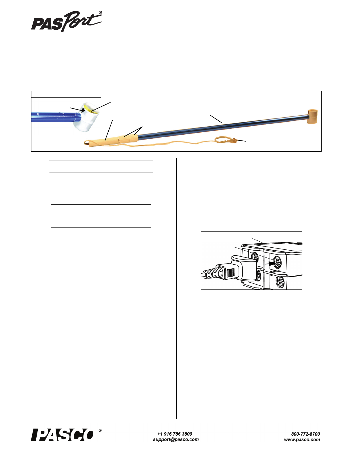
Handle
Depth Scales
(cm and in)
Impeller
Housing
PASPORT
Sensor
Plug
Propeller
Close-up view of
the propeller
Flow Direction
Arrow
Ribbed
Sections
Sensor Plug
PASPORT
Input Port
Interface
Flow Rate/Temperature Sensor
PS-2130
012-08622B
.
*See the PASCO catalog or the PASCO web site at www.pasco.com
for more information.
Introduction
The PS-2130 Flow Rate/Temperature Sensor measures the
flow rate and temperature of moving water. The impeller
housing contains a propeller mounted on a low friction brass
shaft. Magnets on the propeller revolve as the propeller
turns, and the revolutions are recorded by a Hall effect sensing element. The Hall effect sensing element minimizes artifact pulses that sometimes occur with a magnetic reed
switch. The propeller makes 4.31 revolutions for each linear
foot of water that passes, so 8.62 pulses are produced for
each linear foot of water passing through the housing.
The Flow Rate Sensor transforms the kinetic energy of moving water into electric pulses that are converted into velocity
measurements and viewed in the data acquisition software.
The Flow Rate Sensor measures in feet per second (ft/s) or
meters per second (m/s). The built-in temperature sensor
measures temperature at the same point as the flow rate is
measured.
The tube of the Flow Rate/Temperature Sensor can be
extended to a total length of 7 feet (2.13 m). The outer part of
the tube has depth markings in inches and centimeters. The
Included Item
Flow Rate/Temperature Sensor
Required Items*
PASCO Interface
PASCO Data Acquisition Software
impeller housing has an arrow to indicate the direction to
hold the sensor so that the water flow can be measured.
The sensor is designed to work with a PASPORT-compatible
interface (such as the PS-2002 Xplorer GLX hand-held datalogger) and PASCO data acquisition software.
Sensor Operation
• Connect the sensor plug to one of the PASPORT input
ports of a PASCO PASPORT-compatible interface.
NOTE: If more distance is needed between the sensor and
the interface, plug the sensor into a Sensor Extension Cable
(PS-2500) and then plug the cable into the interface.
Safety CAUTION!
SAFETY TIPS: When using the Flow Rate Sensor outdoors,
follow standard water and outdoor safety precautions. The
Flow Rate Sensor is recommended for use in streams and
lakes (avoid turbulent waters or rivers). Always be aware of
potential hazardous conditions in the area. Do not use the
sensor in high winds, adverse weather or avalanche conditions, near potential land or mudslides, or when standing on
unstable ground. Before using the sensor, survey the area.
When inserting the Flow Rate Sensor into water, stand on
stable ground or in shallow water. Keep the Flow Rate Sensor away from water that has lots of debris or potential obstacles. If the propeller or sensor becomes lodged in a high
velocity current or near a drop off, do not attempt to remove
Page 2
Flow Rate/Temperature Sensor Specifications
the sensor. In high risk situations, only allow a water patrol
officer or public safety official to remove the sensor.
• Always hold the pole vertically and keep the propeller in
the direction of the current flow, facing upstream.
• When taking a reading, keep the handle steady.
• If the flow rate reading suddenly falls to zero midstream, check the propeller for debris. When sand or
other particles become lodged in the propeller, the propeller stops turning and the reading drops to zero.
• Erratic readings may occur with turbulent water flow. If
measuring flow from a stream or creek, keep the housing in a stable position, away from rocks and turbulence. If measuring in low depths, the housing can be set
on the stream bed for a more stable reading.
• Do not connect the propeller housing to pipes or other
tubing.
• If using the Flow Rate Sensor from a boat, tether the
boat such that the boat does not move during measurements. Boat movement may interfere with an accurate
flow rate measurement.
Making Measurements
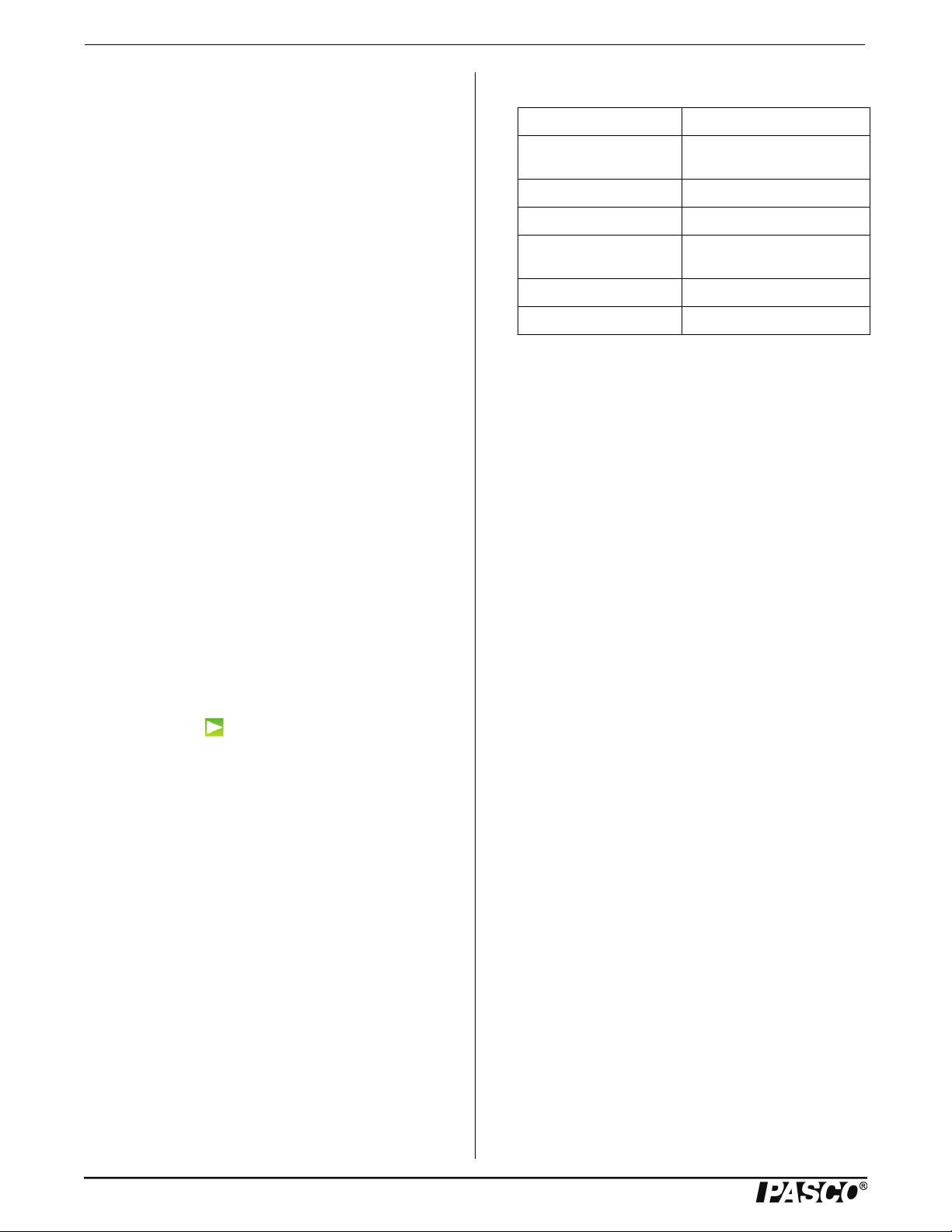
Specifications
Item Value
Ranges: Flow Rate: 0.3 to 13 ft/s
Temperature: -3° to 42°C
Accuracy: 0.1 ft/s
Pulse Frequency: 8.62 per linear foot
Unit Options: feet/second, meters/second,
total pulses
Probe Length: 1 meter to 2.13 m
Minimum Depth: 1.5 in (3.8 cm)
Extending the Sensor Tube
Between the handle and the sensor tube are two ribbed sections. One of them is slightly longer and larger in diameter.
To extend the tube, hold the smaller ribbed section firmly
with one hand, and turn the other ribbed section counterclockwise (left-to-right) to loosen it. When the ribbed section
is loose, pull the handle to extend the tube to the desired
length. Turn the larger ribbed section clockwise
(right-to-left) to tighten it and hold the tube in place.
Using SPARKvue Software
• Connect the sensor plug to a PASPORT input port on a
SPARKvue-compatible interface and start the software.
The sensor parameter screen opens and shows the list of
measurements for the sensor.
• In the sensor parameter screen, touch a measurement,
and then touch ‘Show’ to open a graph display of the
measurement.
• Touch “Start”( ) to begin recording data.
Using the Xplorer GLX
• Turn on the Xplorer GLX and connect the sensor plug to
a port on the top. A Graph display of Flow Rate versus
Time opens automatically.
•Press the Sta rt/Stop key (s) to begin recording data.
Press the same key again to stop recording.
Calibration Information
Calibration of the Flow Rate/Temperature Sensor is not
needed.
More Information
For more information about collecting, recording, displaying
and analyzing data, refer to the User’s Guide or Online Help
System for the data acquisition software.
Maintenance
Storage
When not using the Flow Rate Sensor, store the sensor in a
dry environment to avoid corrosion. If necessary, periodically lubricate the propeller with silicone oil.
Suggested Activity: Measuring the Flow Rate and Temperature in a Stream
• Connect the sensor plug to the interface and turn on the
interface.
• Place the Flow Rate/Temperature Sensor impeller housing about two inches below the surface of a moving
stream of water. Hold the sensor steady.
• Start recording data.
• On a piece of paper, draw a diagram of the stream and
shoreline. On the stream diagram, mark the point where
you took the measurement. Next to the point, record the
flow rate and temperature readings.
• Repeat the data recording process as several depths and
locations in the stream of water.
• Compare the flow rate and temperature at the different
depths and locations.
Using the Flow Rate Sensor to Estimate Total Wat er Outpu t
• With a measuring tape, measure the width of the stream
of water (shore-to-shore) and record the width in meters.
• With the Flow Sensor’s depth measurement scale, take
depth measurements in meters at equally spaced inter-
2
012-08622B
Page 3

Model No.PS-2130 Technical Support
Stream Width
interval
vals across the stream. For each measurement, submerge
the impeller housing until it rests on the stream bed.
Keep the sensor vertical. Record each depth.
• Connect the sensor plug to the interface and take a flow
rate measurement in meters/second for each interval.
Take a separate data run for each measurement.
Estimating Total Water Output
• Calculate the approximate cross-sectional area of the
stream. Multiply each interval width by each depth you
measured to determine the area for each interval. Add
the areas for each interface together to object the
approximate total cross-sectional area of the stream.
• Examine the data to find the average flow rate for each
interface. Average the flow rates recorded for each of
the intervals to get an overall flow rate.
• Determine the total water output by multiplying the
average flow rate by the total cross-sectional area of the
stream.
Limited Warranty For a description of the product warranty, see the
PASCO catalog. Copyright The PASCO scientific Instruction Sheet
is copyrighted with all rights reserved. Permission is granted to
non-profit educational institutions for reproduction of any part of this
manual, providing the reproductions are used only in their laboratories and classrooms, and are not sold for profit. Reproduction under
any other circumstances, without the written consent of PASCO scientific, is prohibited. Trademarks PASCO, PASCO Capstone,
PASPORT, SPARK Science Learning System, SPARK SLS, and
SPARKvue are trademarks or registered trademarks of PASCO scientific, in the United States and/or in other countries. For more information visit www.pasco.com/legal.
Product End of Life Disposal Instructions:
This electronic product is subject to disposal and recycling regulations that vary by country and region. It is your responsibility to recycle your electronic equipment per your local environmental laws and
regulations to ensure that it will be recycled in a manner that protects
human health and the environment. To find out where you can drop
off your waste equipment for recycling, please contact your local
waste recycle/disposal service, or the place where you purchased
the product.
The European Union WEEE (Waste Electronic
and Electrical Equipment) symbol (to the right)
and on the product or its packaging indicates
that this product must not be disposed of in a
standard waste container.
More Information
For the latest information about the Flow Rate/Temperature
Sensor, visit www.pasco.com and enter “PS-2130” in the
Search window.
Technical Support
For assistance with any PASCO product, contact PASCO at:
Address: PASCO scientific
10101 Foothills Blvd.
Roseville, CA 95747-7100
Phone: +1 916-462-8384 (worldwide)
877-373-0300 (U.S.)
E-mail: support@pasco.com
Web www.pasco.com
012-08622B
3
 Loading...