

Parweld XTT-200 DC P Operator's Manual

OPERATOR MANUAL
ISSUE 1
XTT-200 DC P

Welcome
Thank you and congratulations on choosing Parweld. This Owner’s Manual is designed to help you get
the most out of your Parweld products. Please take time to read the Safety precautions. They will
help you protect yourself against potential hazards in the workplace. With proper maintenance this
equipment should provide years of reliable service. All our systems conform to ISO9001: 2008 and
are independently audited by NQA.
The entire product range carries the CE mark, and is constructed in accordance with European
directives and the product specic standards where they apply.
Further Information
Parweld is the UK’s leading manufacturer of MIG, TIG and Plasma torches and consumables.
For more information about Parweld’s complete range visit: www.parweld.com

CONTENTS
Contents
Page
1.0 Safety Precautions 4
2.0 Product description 5
3.0 Technical Specications 5
4.0 Description of controls 6
5.0 Installation 6
5.1 Unpacking the Machine 6
5.2 Location 6
5.3 Input and grounding connection 7
5.4 Output Polarity Connections 7
5.5 Torch Installation 7
5.6 Work return lead connection 7
6.0 Operation 7
6.1 MMA Welding guide 7
6.2 Basic TIG welding guide 8
7.0 Fault nding 9
8.0 Accessories 13
8.1 Torch spares 14
8.3 Gas equipment 13
9.0 EC declaration of conformity 16
9.1 RoHS Compliance Declaration 16
9.2 WEEE Statement 17
9.3 Statement of warranty 17

www.parweld.com
4
1.0 Safety Precautions
ELECTRIC SHOCK can kill.
Touching live electrical parts can cause fatal shocks or severe burns.
The electrode and work circuit is electrically live whenever the output
is on. The input power circuit and machine internal circuits are also
live when power is on.
Do not touch live electrical parts.
Wear dry, sound insulating gloves and body protection.
Insulate yourself from work and ground using dry insulating mats
or covers big enough to prevent any physical contact with the work
ground.
Additional safety precautions are required when any of the following
electrically hazardous conditions are present: in damp locations
or while wearing wet clothing; on metal structures such as oors,
gratings, or scaffolds; when in cramped positions such as sitting,
kneeling, or lying; or when there is a high risk of unavoidable or
accidental contact with the work piece or ground.
Disconnect input power before installing or servicing this equipment.
Lockout/tagout input power according to Safety Standards.
Properly install and ground this equipment according to national and
local standards.
Always verify the supply ground - check and ensure that input power
cable ground wire is properly connected to ground terminal in the
receptacle outlet.
When making input connections, attach proper grounding conductor
rst - double-check connections.
Frequently inspect input power cable for damage or bare wiring replace cable immediately if damaged - bare wiring can kill.
Turn off all equipment when not in use.
Do not use worn, damaged, under sized, or poorly spliced cables.
Do not drape cables over your body.
If earth grounding of the work piece is required, ground it directly
with a separate cable.
Do not touch electrode if you are in contact with the work, ground, or
another electrode from a different machine.
Use only well-maintained equipment. Repair or replace damaged
parts at once. Maintain unit according to manual.
Wear a safety harness if working above oor level.
Keep all panels and covers securely in place.
Clamp work cable with good metal-to-metal contact to work piece or
worktable as near the weld as practical.
Insulate work clamp when not connected to work piece to prevent
contact with any metal object.
Welding produces fumes and gases. Breathing these fumes and
gases can be hazardous to your health.
FUMES AND GASES can be hazardous.
Keep your head out of the fumes. Do not breathe the fumes.
If inside, ventilate the area and/or use local forced ventilation at the
arc to remove welding fumes and gases.
If ventilation is poor, wear an approved respirator.
Read and understand the Material Safety Data Sheets (MSDS’s) and
the manufacturer’s instructions for metals, consumable, coatings,
cleaners, and de-greasers.
Work in a conned space only if it is well ventilated, or while wearing
an air-supplied respirator. Always have a trained watch person
nearby. Welding fumes and gases can displace air and lower the
oxygen level causing injury or death. Be sure the breathing air is
safe.
Do not weld in locations near de-greasing, cleaning, or spraying
operations. The heat and rays of the arc can react with vapours to
form highly toxic and irritating gases.
Do not weld on coated metals, such as galvanized, lead, or cadmium
plated steel, unless the coating is removed from the weld area, the
area is well ventilated, and while wearing an air-supplied respirator.
The coatings and any metals containing these elements can give off
toxic fumes if welded.
ARC RAYS can burn eyes and skin.
Arc rays from the welding process produce intense, visible and
invisible (ultraviolet and infrared) rays that can burn eyes and skin.
Sparks y off from the weld.
Wear an approved welding helmet tted with a proper shade of lter
lense to protect your face and eyes when welding or watching
Wear approved safety glasses with side shields under your helmet.
Use protective screens or barriers to protect others from ash, glare
and sparks; warn others not to watch the arc.
Wear protective clothing made from durable, ame resistant material
(leather, heavy cotton, or wool) and foot protection. Welding on
closed containers, such as tanks, drums, or pipes, can cause them
to blow up. Sparks can y off from the welding arc. The ying sparks,
hot work piece, and hot equipment can cause res and burns.
Accidental contact of electrode to metal objects can cause sparks,
explosion, overheating, or re. Check and be sure the area is safe
before doing any welding.
WELDING can cause re or explosion.
Remove all ammables within 10m of the welding arc. If this is not
possible, tightly cover them with approved covers.
Do not weld where ying sparks can strike ammable material.
Protect yourself and others from ying sparks and hot metal.
Be alert that welding sparks and hot materials from welding can
easily go through small cracks and openings to adjacent areas.
SAFETY

5
Watch for re, and keep a re extinguisher nearby. Be aware that
welding on a ceiling, oor, bulkhead, or partition can cause re on
the hidden side.
Do not weld on closed containers such as tanks, drums, or pipes,
unless they are properly prepared according to local regulations
Connect work cable to the work as close to the welding area as
practical to prevent welding current from travelling along, possibly
unknown paths and causing electric shock, sparks, and re hazards.
Wear oil-free protective garments such as leather gloves, heavy
shirt, cufess trousers, high shoes, and a cap. Remove any
combustibles, such as a butane lighter or matches, from your person
before doing any welding.
FLYING METAL can injure eyes.
Welding, chipping, wire brushing, and grinding cause sparks and
ying metal. As welds cool they can throw off slag. Wear approved
safety glasses with side shields even under your welding helmet.
BUILDUP OF GAS can injure or kill.
Shut off shielding gas supply when not in use. Always ventilate
conned spaces or use approved air-supplied respirator.
HOT PARTS can cause severe burns.
Do not touch hot parts with bare hands.
Allow cooling period before working on gun or torch.
To handle hot parts, use proper tools and/or wear heavy, insulated
welding gloves and clothing to prevent burns.
MAGNETIC FIELDS can affect pacemakers.
Pacemaker wearers keep away.
Wearers should consult their doctor before going near arc welding,
gouging, or spot welding operations.
NOISE can damage hearing.
Noise from some processes or equipment can damage hearing.
Wear approved ear protection if noise level is high.
Shielding gas cylinders contain gas under high pressure.
CYLINDERS can explode if damaged.
Protect compressed gas cylinders from excessive heat, mechanical
shocks, physical damage, slag, open ames, sparks, and arcs.
Install cylinders in an upright position by securing to a stationary
support or cylinder rack to prevent falling or tipping. Keep cylinders
away from any welding or other electrical circuits. Never drape a
welding torch over a gas cylinder. Never allow a welding electrode to
touch any cylinder. Never weld on a pressurized cylinder - explosion
will result. Use only correct shielding gas cylinders, regulators,
hoses, and ttings designed for the specic application; maintain
them and associated parts in good condition.
Turn face away from valve outlet when opening cylinder valve.
Use the right equipment, correct procedures, and sufcient number
of persons to lift and move cylinders.
Read and follow instructions on compressed gas cylinders,
associated equipment, and Compressed Gas Association (CGA)
recommendations.
2.0 Product Description
This welding machine is manufactured using
advanced inverter technology. The input voltage is rectied to
DC and then inverted to high frequency AC voltage. before being
converted back to DC for the output .This allows the use of a much
smaller transformer and so allowing weight saving and improved
power efciency.
3.0 Technical
Specications
XTT 200 DC P
Input
voltage
230V +/- 10%
Process
TIG MMA
Frequency
50/60Hz
Input
current
31A max
20 eff
36A max
24 eff
Fuse rating
32A 32A
Output OCV
63
Output load
voltage
10-17.2V 20-27.2
Output
Current
5-200A 5-170A
SAFETY
www.parweld.com
6
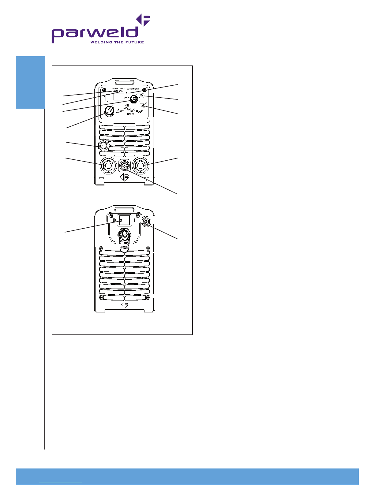
6) TIG mode-Lift Arc, LIFT-ARC mode can be selected for 2T or 4T
operation
Main amperage control. This control is used to control the welding
current in TIG and MMA modes. Please not the maximum output
of this machine varies depending upon the input voltage and the
process selected, refer to the technical data.
7) TIG mode-HF start, TIG HF start mode can be selected for 2T or
4T operation
Downslope/Arc force. This control is dual function
in TIG mode it controls the downslope time for the welding current
after the trigger is released from 0 to 10 seconds.
In MMA mode it allows adjustment of the welding Arc force so giving
control of penetration.
9) Main control knob This knob allow selection and adjustment of
the welding parameters in accordance with the led lights to the right
and above (MMA). the welding mode selected with control 4 will
determine which of the LEDs can be selected. Rotating the knob
will toggle through the available parameters. Pressing the knob
will select that parameter (the display will ash while it is selected
) rotating the know while the display is ashing will adjust the
parameter pressing the knob again will deselect or wait 3 seconds.
10) Positive connection This is used to connect the electrode
holder in MMA or the earth lead in TIG welding.
11) Negative connection. This is used to connect the earth lead in
MMA welding or the torch in TIG welding.
12) Control socket This is used to control the machine remotely
using a trigger or amperage control.
13) Gas Output connection This is a 3/8 BSP connection for the
gas output used in TIG welding.
14) Gas inlet This is a nipple connection for the gas input used in
TIG welding.
5.0 Installation
Read entire installation section before starting installation.
SAFETY PRECAUTIONS
• ELECTRIC SHOCK can kill.
• Only qualied personnel should perform this installation.
• Only personnel that have read and understood the Operating
Manual should install and operate this equipment.
• Machine must be grounded per any national, local or other
applicable electrical regulations.
• The power switch is to be in the OFF position when installing
work cable and electrode cable and when connecting other
equipment.
5.1 Unpacking the Machine
Carefully remove the machine from the packaging, we recommend
you retain the packaging until the machine has been fully installed
and tested incase it has been damaged in transit and has to be
returned to the re-seller.
5.2 Location
Be sure to locate the welder according to the following guidelines:
In areas, free from moisture and dust.
Ambient temperature between 0-40
0
C.
In areas, free from oil, steam and corrosive gases.
4.0 Description of Controls
1) ON OFF Switch for switching on or off the mains supply to the
machine. Note the output of the machine is permanently on in MMA
mode unless the on/off switch is in the off position.
2) Fault light This indicates a fault or over temperature condition
with the machine refer to the fault nding section for further
information
3) Power light This indicates mains power is applied to the machine
and that the machine is currently switched on when the light is
illuminated.
4) Process selector. This rotary knob has 7 positions and selects
the modes as listed following . The centre position is TIG welding
with 2 touch trigger control (momentary). The top position is TIG
welding with 4 touch control (latching).
5) MMA welding and will latch on the output when in this position
Gas test this allow purging of the gas an testing of the gas ow.
1
5
6
7
8
10
12
14
3
2
4
9
13
11
CONTROLS
 Loading...