


XTP-63
OPERATOR MANUAL
ISSUE 1

Welcome
Thank you and congratulations on choosing Parweld. This Owner’s Manual is designed to help you get
the most out of your Parweld products. Please take time to read the Safety precautions. They will
help you protect yourself against potential hazards in the workplace. With proper maintenance this
equipment should provide years of reliable service. All our systems conform to ISO9001: 2008 and
are independently audited by NQA.
The entire product range carries the CE mark, and is constructed in accordance with European
directives and the product specic standards where they apply.
Further Information
Parweld is the UK’s leading manufacturer of MIG, TIG and Plasma torches and consumables.
For more information about Parweld’s complete range visit: www.parweld.com

Contents
Page
1.0 Safety Precautions 4
2.0 Product description 5
3.0 Technical Specications 5
4.0 Description of controls 6
5.0 Installation 6
5.1 Unpacking the Machine 6
5.2 Location 6
5.3 Input and grounding connection 6
5.4 Torch Installation 7
5.5 Work return lead connection 7
6.0 Operation 7
6.1 Consumable parts 7
6.2 switching on the machine 7
6.3 Setting the Air pressure 7
6.4 Getting ready to Cut 7
6.5 Cut quality 8
6.6 Piercing 8
6.7 Operating the Torch 8
7.0 Fault nding 8
8.0 Accessories 10
8.1 Torch spares 10
9.0 EC declaration of conformity 11
9.1 RoHS Compliance Declaration 11
9.2 WEEE Statement 12
9.3 Statement of warranty 12

SAFETY
1.0 Safety Precautions
ELECTRIC SHOCK can kill.
Touching live electrical parts can cause fatal shocks or severe burns.
The electrode and work circuit is electrically live whenever the output
is on. The input power circuit and machine internal circuits are also
live when power is on.
Do not touch live electrical parts.
Wear dry, sound insulating gloves and body protection.
Insulate yourself from work and ground using dry insulating mats
or covers big enough to prevent any physical contact with the work
ground.
Additional safety precautions are required when any of the following
electrically hazardous conditions are present: in damp locations
or while wearing wet clothing; on metal structures such as oors,
gratings, or scaffolds; when in cramped positions such as sitting,
kneeling, or lying; or when there is a high risk of unavoidable or
accidental contact with the work piece or ground.
Disconnect input power before installing or servicing this equipment.
Lockout/tagout input power according to Safety Standards.
Properly install and ground this equipment according to national and
local standards.
Always verify the supply ground - check and ensure that input power
cable ground wire is properly connected to ground terminal in the
receptacle outlet.
Cutting produces fumes and gases. Breathing these fumes and
gases can be hazardous to your health.
FUMES AND GASES can be hazardous.
Keep your head out of the fumes. Do not breathe the fumes.
If inside, ventilate the area and/or use local forced ventilation at the
arc to remove welding fumes and gases.
If ventilation is poor, wear an approved respirator.
Read and understand the Material Safety Data Sheets (MSDS’s) and
the manufacturer’s instructions for metals, consumable, coatings,
cleaners, and de-greasers.
Work in a conned space only if it is well ventilated, or while wearing
an air-supplied respirator. Always have a trained watch person
nearby. Cutting fumes and gases can displace air and lower the
oxygen level causing injury or death. Be sure the breathing air is
safe.
Do not cut in locations near de-greasing, cleaning, or spraying
operations. The heat and rays of the arc can react with vapours to
form highly toxic and irritating gases.
Do not cut on coated metals, such as galvanized, lead, or cadmium
plated steel, unless the coating is removed from the cut area, the
area is well ventilated, and while wearing an air-supplied respirator.
The coatings and any metals containing these elements can give off
toxic fumes if cut.
ARC RAYS can burn eyes and skin.
Arc rays from the cutting process produce intense, visible and
invisible (ultraviolet and infrared) rays that can burn eyes and skin.
Sparks y off from the weld.
When making input connections, attach proper grounding conductor
rst - double-check connections.
Frequently inspect input power cable for damage or bare wiring replace cable immediately if damaged - bare wiring can kill.
Turn off all equipment when not in use.
Do not use worn, damaged, under sized, or poorly spliced cables.
Do not drape cables over your body.
If earth grounding of the work piece is required, ground it directly
with a separate cable.
Do not touch torch tip while machine is witched on.
Use only well-maintained equipment. Repair or replace damaged
parts at once. Maintain unit according to manual.
Wear a safety harness if working above oor level.
Keep all panels and covers securely in place.
Clamp work cable with good metal-to-metal contact to work piece or
worktable as near the weld as practical.
Insulate work clamp when not connected to work piece to prevent
contact with any metal object.
Wear an approved welding helmet tted with a proper shade of lter
lense to protect your face and eyes when welding or watching
Wear approved safety glasses with side shields under your helmet.
Use protective screens or barriers to protect others from ash, glare
and sparks; warn others not to watch the arc.
Wear protective clothing made from durable, ame resistant material
(leather, heavy cotton, or wool) and foot protection. Cutting on closed
containers, such as tanks, drums, or pipes, can cause them to blow
up. Sparks can y off from the cutting arc. The ying sparks, hot
work piece, and hot equipment can cause res and burns. Accidental
contact of electrode to metal objects can cause sparks, explosion,
overheating, or re. Check and be sure the area is safe before doing
any cutting.
WELDING can cause re or explosion.
Remove all ammables within 10m of the welding arc. If this is not
possible, tightly cover them with approved covers.
Do not weld where ying sparks can strike ammable material.
Protect yourself and others from ying sparks and hot metal.
Be alert that welding sparks and hot materials from welding can
easily go through small cracks and openings to adjacent areas.
Watch for re, and keep a re extinguisher nearby. Be aware that
4
www.parweld.com
cutting on a ceiling, oor, bulkhead, or partition can cause re on the
hidden side.
Do not cut on closed containers such as tanks, drums, or pipes,
unless they are properly prepared according to local regulations
Connect work cable to the work as close to the welding area as
practical to prevent cutting current from travelling along, possibly
unknown paths and causing electric shock, sparks, and re hazards.
Wear oil-free protective garments such as leather gloves, heavy
shirt, cufess trousers, high shoes, and a cap. Remove any
combustibles, such as a butane lighter or matches, from your person
before doing any cutting.
FLYING METAL can injure eyes.
Cutting, chipping, wire brushing, and grinding cause sparks and
ying metal. As cuts cool they can throw off slag. Wear approved
safety glasses with side shields even under your welding helmet.
Read and follow instructions on compressed gas cylinders,
associated equipment, and Compressed Gas Association (CGA)
recommendations.
SAFETY
2.0 Product Description
This welding machine is manufactured using
advanced inverter technology. The input voltage is rectied to
DC and then inverted to high frequency AC voltage. Before being
converted back to DC for the output .This allows the use of a much
smaller transformer and so allowing weight saving and improved
power efciency.
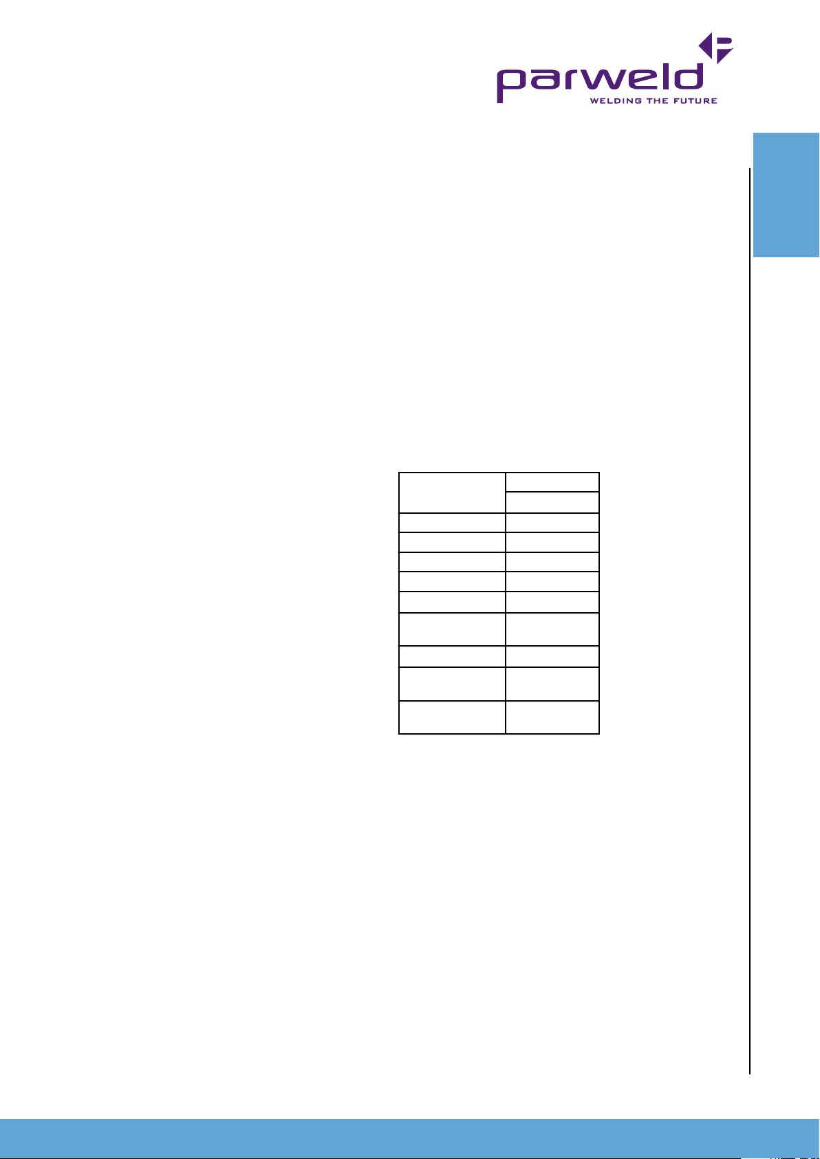
3.0 Technical
BUILDUP OF GAS can injure or kill.
Shut off the gas supply when not in use. Always ventilate conned
spaces or use approved air-supplied respirator.
HOT PARTS can cause severe burns.
Do not touch hot parts with bare hands.
Allow cooling period before working on gun or torch.
To handle hot parts, use proper tools and/or wear heavy, insulated
welding gloves and clothing to prevent burns.
MAGNETIC FIELDS can affect pacemakers.
Pacemaker wearers keep away.
Wearers should consult their doctor before going near arc welding,
gouging, or spot welding operations.
NOISE can damage hearing.
Noise from some processes or equipment can damage hearing.
Wear approved ear protection if noise level is high.
Shielding gas cylinders contain gas under high pressure.
Specications
Data
Input voltage
Frequency
Input current
Fuse rating
Output OCV
Output load
voltage
Output Current
Cutting capacity
Production
Cutting Capacity
Severance
400V +/- 10%
50/60Hz
12A MAX
16A (D rating)
480V
88-96V
20-60A DC
20mm
30mm
CYLINDERS can explode if damaged.
Protect compressed gas cylinders from excessive heat, mechanical
shocks, physical damage, slag, open ames, sparks, and arcs.
Install cylinders in an upright position by securing to a stationary
support or cylinder rack to prevent falling or tipping. Keep cylinders
away from any welding or other electrical circuits. Never drape a
cutting torch over a gas cylinder. Never allow a cutting tip to touch
any cylinder. Never cut a pressurized cylinder - explosion will result.
Use only correct shielding gas cylinders, regulators, hoses, and
ttings designed for the specic application; maintain them and
associated parts in good condition.
Turn face away from valve outlet when opening cylinder valve.
Use the right equipment, correct procedures, and sufcient number
of persons to lift and move cylinders.
5

4.0 Description of Controls
2
5
8) Torch connector
9) Earth lead connector.
10) Air line connector
11) Consumable holder
CONTROLS
3
6
4
7
8
9
5.0 Installation
Read entire installation section before starting installation.
SAFETY PRECAUTIONS
• ELECTRIC SHOCK can kill.
• Only qualied personnel should perform this installation.
• Only personnel that have read and understood the Operating
Manual should install and operate this equipment.
• Machine must be grounded per any national, local or other
applicable electrical regulations.
• The power switch is to be in the OFF position when installing
work cable and torch and when connecting other equipment.
5.1 Unpacking the Machine
1
10
11
Carefully remove the machine from the packaging, we recommend
you retain the packaging until the machine has been fully installed
and tested incase it has been damaged in transit and has to be
returned to the re-seller.
5.2 Location
Be sure to locate the welder according to the following guidelines:
In areas, free from moisture and dust.
Ambient temperature between 0-40
In areas, free from oil, steam and corrosive gases.
In areas, not subjected to abnormal vibration or shock.
In areas not exposed to direct sunlight or rain.
Place at a distance of 12” (300 mm) or more from walls or similar
that could restrict natural airow for cooling.
0
C.
6
1) ON OFF Switch for switching on or off the mains supply to the
machine. The switch is mounted on the rear panel.
2) Fault light This indicates a fault or over temperature condition
with the machine refer to the fault nding section for further
information
3) Power light This indicates mains power is applied to the machine
and that the machine is currently switched on when the light is
illuminated
4) Output power control for adjustment of the power output of the
machine between 20 and 60Amps.
5) Interlock fault. If this light illuminates it indicates one of the
following. Short circuit between the electrode and tip, front end torch
parts missing or incorrectly tted, Shield cup not tted correctly
(lamp ashes) low air pressure.
6) Output power on. Illuminates when the DC output current is on.
7) Run/Set switch. In the set position the Air can be checked by
pressing the trigger to ensure the air is connected and owing.
www.parweld.com
5.3 Input and grounding connection
WARNING
Before starting the installation, check that your power supply
is adequate for the voltage, amperage, phase, and frequency
specied on the Machine nameplate.
Operate the welding power source from a single-phase 50/60 Hz,
AC power supply. The input voltage must match one of the electrical
input voltages shown on the input data label on the unit nameplate.
The XTP-63 machine can be used on 400V supply and will
automatically adjust itself depending upon the voltage applied.
Refer to the specications table for voltage tolerances.
Have a qualied electrician connect the input plug. For long runs
over 30m , larger copper wires should be used. The green/yellow
wire in the input cable connects to the frame of the machine. This
ensures proper grounding of the machine when the machine plug is
inserted into the receptacle.

5.4 Torch installation
Connect the torch to the machine using the special tool supplied as
illustrated below.
1) Insert the tool into the hole on the outside of the locking ring and
apply pressure to release the locking ring
2) Push the torch connector into the socket on the machine taking
care to line up the pins.
3) Tighten the hand nut on the torch to secure the torch
4) Release pressure on the locking tool and remove
6.2 Switching on the machine
When the machine is switched on it will perform a self
test routing as detailed following.
OPERATION
CAUTION: Before switching on the machine ensure all spares
are tted correctly to the torch and in good condition failure t
spare parts can result in the destruction of the torch head.
5.6 Work return lead connection
Insert the connector in the socket and twist clockwise to lock.
6.0 Operation
WARNING
When using an open arc process, it is necessary to use correct
eye, head, and body protection.
6.1 Consumable parts
The electrode, swirl ring and cutting tip are held in position by the
nozzle; removal of the nozzle allows these parts to be replaced.
Cutting tip size should be selected to match the selected amperage
on the machine and is not related to the thickness of the material to
be cut. Electrodes should be replaced when the insert has eroded
to a depth of no more than 1.2mm failure to replace the electrode
may result in permanent torch damage. The life of the electrode
is dependant upon the cut amperage and the number of starting
operations performed. The higher start frequency and cutting power
will give the shortest electrode life. Check the electrode condition
every 30 minutes of cutting
6.3 Setting the Air pressure
Connect the air line to the rear of the machine
and Switch on the machine. The air supply should be capable of
supplying compressed air at a pressure of 5Bar and a ow rate of
155lpm free air delivery. Switch on the machine and set the toggles
switch on the front panel to SET so that air ows through the torch.
With the air owing ensure the interlock light does not come on, if the
interlock light illuminates then the air supply pressure to the machine
must be increased.
6.4 Getting ready to cut
Use the control knob on the front of the machine to
adjust the require output current, a higher current will give faster
cutting and a lower current slower cutting but more control for detail
cutting. The higher the set current the greater the wear rate will be
for the tip and electrode.
7

6.5 Cut Quality
Cut quality requirements differ depending on
application. Bevel angle may be a major factor when the surface
will be welded after cutting. Dross-free cutting is important when
nish cut quality is desired to avoid a secondary cleaning operation.
Rounding on the top edge of a cut due to wearing from the initial
FAULT
contact of the plasma arc on the work piece. Dross is molten
FINDING
material which is not blown out of the cut area and re-solidies
on the plate. Top spatter is dross which accumulates on the top
surface of the work piece. Excessive dross may require secondary
clean-up operations after cutting. Improper standoff (the distance
between the torch tip and work piece) can adversely affect tip life
as well as shield cup life. Standoff may also signicantly affect the
bevel angle. Reducing standoff generally results in a squarer cut.
A guide clip and crown stand off guide is available to maintain a
constant stand off height. The plasma gas stream swirls as it leaves
the torch. The purpose of the swirl is to maintain a smooth column
of gas. The swirl effect results in one side of a cut being squarer
than the other. Viewed along the direction of travel, the right side of
the cut is squarer than the left. If dross is present on carbon steel,
it is commonly referred to as either “high speed, slow speed, or top
dross”. Dross present on top of the plate is normally caused by too
great a torch to plate distance. Top dross is normally very easy to
remove and can often be wiped off with a welding glove. Slow speed
dross is normally present on the bottom edge of the plate. It can vary
from a light to heavy bead, but does not adhere tightly to the cut
edge, and can be easily scraped off. High speed dross usually forms
a narrow bead along the bottom of the cut edge and is very difcult
to remove. When cutting troublesome steel, it is sometimes useful to
reduce the cutting speed to produce slow speed dross. Any resultant
cleanup can be accomplished by scraping, not grinding. Starting the
Cut Edge Starting For edge starts, hold the torch perpendicular to
the work piece with the front of the tip on the edge of the work piece
at the point where the cut is to start. When starting at the edge of the
plate, do not pause at the edge and force the arc to “reach” for the
edge of the metal. Establish the cutting arc as quickly as possible.
6.6 Piercing
For piercing, angle the torch slightly too direct sparks
away from the torch until the pierce is complete. Start and complete
the pierce close to the cutting line and then continue the cut onto the
line. Hold the torch perpendicular to the work piece after the pierce
is complete. Clean spatter and scale from the outer nozzle and the
tip as soon as possible. A light coating of anti-spatter compound
may be applied to the outside to minimize the amount of scale which
adheres to it. Be careful not to get anti-spatter compound on the
torch tip or other parts.
6.7 Operating the torch
With the torch in starting position press and hold the
trigger. After an initial gas purge, the main arc will come on. Once
on, the main arc remains on as long as the trigger switch is held
down, unless the torch is withdrawn from the work or torch motion
is too slow. If the cutting arc is interrupted, the cutting process must
be restarted. To shut off the torch simply release the trigger switch.
When the switch is released a 15 second post-ow will occur. If the
torch switch is closed during the post-ow, the cutting arc will restart
after switching off the air. Refer to the ow chart below for the
operating sequence.
7.0 Fault Finding
Cutting problems
Description Possible cause Remedy
Torch cuts but not
adequately
Heavy dross on underside of plate
1. Current set too low
2. Torch is being moved
too fast across work
piece
3. Oil or moisture in
torch
Cutting power is to low Increase
1. Increase
current
setting.
2. Reduce
cutting speed
3. Ensure
water trap
on rear of
machine
is empty
(disconnect
air supply
to allow it to
drain). Put
machine
in setting
mode Hold
torch 1/8
inch (3 mm)
from clean
surface while
purging and
observe oil
or moisture
buildup (do
not activate
torch)
cutting power
8
www.parweld.com

Description Possible cause Remedy
Cut is not straight 1.Tip is damaged
2. Cut direction is not
correct.
Power source problems
Cut quality is dependent on the selection of the correct consumable,
maintenance of equipment and proper cutting technique.
Description Possible Cause Remedy
Interlock light
illuminates
when trigger
pressed
Interlock light
ashes when
trigger pressed
Interlock light
illuminates
when trigger
pressed, and
the air ow is
intromittent
Fault light
illuminates
Torch does
not start when
trigger pressed
Air pressure is set to low Adjust air pressure
Outer nozzle or other
consumable not installed
correctly
Cutting tip or electrode
not installed correctly
Short circuit in side the
torch or cable
Machine has over
heated.
Input voltage is to high
Internal machine fault
Machine is in Set mode Change switch to
Reduce
travel speed;
ensure
correct tip
is tted for
amperage.
Observe
correct
standoff and
direction of
cut
to 5Bar. Restart the
power source
re-assemble front
end spares to
ensure outer nozzle
is seated fully.
Restart the power
source
re-install the tip and
electrode. Restart
the power source
Have it checked by
a qualied engineer
Allow machine to
cool with fan running
Ensure input voltage
is correct
Have machine
inspected by
qualied engineer
run mode on front
panel
FAULT
FINDING
ROUTINE MAINTENANCE
The only routine maintenance required for the power supply is a
thorough cleaning and inspection, with the frequency depending on
the usage and the operating environment.
Warning
Disconnect primary power at the source before removing the
cover. Wait at least two minutes before opening the cover to
allow the primary capacitors to discharge.
To clean the unit, remove the screws securing the outer cover,
lift off the outer cover and use a vacuum cleaner to remove any
accumulated dirt and dust. The unit should also be wiped clean,
if necessary; with solvents that are recommended for cleaning
electrical apparatus.
9

ACCESSORY
8.0 Accessories
Parweld XT4000
Rating: 60A @ 80% Duty Cycle, EN60974-7
9
8
3
4
1
2
11
12
10
8
5
6
7
1
Technical Data
Voltage Class M
Standard Length 6mt
Air Consumption 110 l/min
Air Pressure 5 Bar
Duty Cycle 80% 60A
Start Method Non HF with Pilot Arc
Torch Model
Stock Code Description
XT4000 Plasma Torch x 6mt Central Connector
Consumables
Stock Code Description
1 XT4008 Double Pointed Spacer
2 XT4007 Retaining Cap
3 XT4005-08 Cutting Tip 0.8mm 20-30A
4 XT4005-09 Cutting Tip 0.9mm 30-40A
5 XT4005-10F Flat Cutting Tip 1.0mm 40-50A
XT4005-11F Flat Cutting Tip 1.1mm 50-60A
6 XT4005-08L Extended Cutting Tip 0.8mm 20-30A
7 XT4005-09L Extended Cutting Tip 0.9mm 30-40A
8 XT4006 Gas Distributor
9 XT4003 Electrode
10 XT4003L Extended Electrode
11 XT4010 O Ring
12 XT4001 Torch Head
10
www.parweld.com

9.0 EC declaration of conformity
Hereby we declare that the machines as stated below
Type: XTP-63
Conform to the EC Directives:
Low Voltage Directive 2006/95/EC
EMC Directive 2004/108/EC
Harmonised European standard: EN/IEC 60974-1
This is to certify that the tested sample is in conformity with all provisions of the above detailed EU directives and product standards.
EC DECL’
9.1 Rohs Compliance Declaration
Directive 2011/65/EU of the European Parliament
Restriction of use of certain hazardous substances in electrical and electronic equipment
Type: XTP-63
The above listed products are certied to be compliant with the rohs directive with all homogeneous component parts being controlled to
ensure material contents as per the list below.
Cadmium 0.01% by weight
Lead 0.1% by weight
Mercury 0.1% by weight
Hexavalent chromium 0.1% by weight
Polybrominated biphenyl’s (pbbs) 0.1% by weight
Polybrominated diphenyl ethers (pbdes) 0.1% by weight
It should be noted that under specic exempted applications, where lead is used as an alloying element the following limits are applied in
accordance with the regulations.
Copper and copper alloy parts use less than 4% by weight of each homogeneous component.
Steel and steel alloy parts use less than 4% by weight of each homogeneous component.
Aluminium and aluminium alloy parts use less than 4% by weight of each homogeneous component.
Only dispose off in authorised sites for electrical and electronic waste do not dispose of with general refuse or landll waste.
11

WEEE
9.2 WEEE Statement
WEEE (Waste Electrical & Electronic Equipment) 2002/96/EC
In relation to implementing the legislation, Parweld has established relevant recycling and recovery methods. We have been fully compliant
against the marking requirements since August 2005. Parweld is registered in the UK with the Environment agency as detailed below. For
WEE compliance outside the UK please contact your supplier/Importer
Parweld is registered with a compliance scheme Ofcial registration number is WEE/FD0255QV
When your equipment reaches the end of its service life you should return it to Parweld where it will be reconditioned or processed for
recycling.
9.3 Statement of warranty
Limited Warranty:
Parweld Ltd, hereafter, “Parweld” warrants its customers that its products will be free of defects in workmanship or material. Should any failure
to conform to this warranty appear within the time period applicable to the Parweld products as stated below, Parweld shall, upon notication
thereof and substantiation that the product has been stored, installed, operated, and maintained in accordance with Parweld’s specications,
instructions, recommendations and recognized standard industry practice, and not subject to misuse, repair, neglect, alteration, or accident,
correct such defects by suitable repair or replacement, at Parweld’s sole option, of any components or parts of the product determined by
Parweld to be defective.
Parweld makes no other warranty, express or implied. This warranty is exclusive and in lieu of all others, including, but not limited to any
warranty of merchantability or tness for any particular purpose.
Limitation of Liability:
Parweld shall not under any circumstances be liable for special, indirect or consequential damages, such as, but not limited to, lost prots and
business interruption. The remedies of the purchaser set forth herein are exclusive and the liability of Parweld with respect to any contract, or
anything done in connection therewith such as the performance or breach thereof, or from the manufacture, sale, delivery, resale, or use of any
goods covered by or furnished by Parweld whether arising out of contract, negligence, strict tort, or under any warranty, or otherwise, shall not,
except as expressly provided herein, exceed the price of the goods upon which such liability is based. No employee, agent, or representative
of Parweld is authorized to change this warranty in any way or grant any other warranty.
Purchaser’s rights under this warranty are void if replacement parts or accessories are used which in Parweld’s sole judgement may impair the
safety or performance of any Parweld product.
Purchaser’s rights under this warranty are void if the product is sold to purchaser by non-authorized persons.
The warranty is effective for the time stated below beginning on the date that the authorized Distributor delivers the products to the purchaser.
Notwithstanding the foregoing, in no event shall the warranty period extend more than the time stated plus one year from the date Parweld
delivered the product to the authorized distributor.
12
www.parweld.com

www.parweld.com
13

Parweld Limited
Bewdley Business Park
Long Bank
Bewdley
Worcestershire
England
DY12 2TZ
tel. +44 1299 266800
fax. +44 1299 266900
www.parweld.com
info@parweld.co.uk
 Loading...