

Parweld XTM303C Operator's Manual
XTM303C
OPERATOR MANUAL
ISSUE 3

Welcome
Thank you and congratulations on choosing Parweld. This Owner’s Manual is designed to help you get
the most out of your Parweld products. Please take time to read the Safety precautions. They will
help you protect yourself against potential hazards in the workplace. With proper maintanance this
equipment should provide years of reliable service. All our systems conform to ISO9001: 2000 and
are independently audited by NQA.
The entire product range carries the CE mark, and is constructed in accordance with European
directives and the product specic standards where they apply.
Further Information
Parweld is the UK’s leading supplier of MIG, TIG and Plasma torches and consumables.
For more information about Parweld’s complete range visit: www.parweld.com

Contents
Page
1.0 Safety Precautions 4
2.0 Product description 5
3.0 Technical Specications 6
4.0 Description of controls 6
5.0 Installation 7
5.1 Unpacking the Machine 7
5.2 Location 7
5.3 Input and grounding connection 7
5.4 Output Polarity Connections 7
5.5 Changing drive roll sets 7
5.6 Welding wire installation 7
5.7 Torch installation 8
CONTENTS
5.8 Work return lead connection 9
5.9 Shielding gas connection 9
6.0 Operation 9
6.1 Feeding wire electrode 9
6.2 Optimising Weld parameters 9
6.2 Additional welding controls 9
7.0 Fault nding 10
8.0 Accessories 11
8.1 Drive rolls 11
8.2 Torch spares 12
8.3 Gas equipment 13
9.0 EC declaration of conformity 14
9.1 RoHS Compliance Declaration 14
9.2 WEEE Statement 15
9.3 Statement of warranty 15

1.0 Safety Precautions
ELECTRIC SHOCK can kill.
Touching live electrical parts can cause fatal shocks or severe burns.
The electrode and work circuit is electrically live whenever the output
is on. The input power circuit and machine internal circuits are also
live when power is on. In semiautomatic or automatic wire welding,
the wire, wire reel, drive roll housing, and all metal parts touching the
welding wire are electrically live. Incorrectly installed or improperly
grounded equipment is a hazard.
Do not touch live electrical parts.
Wear dry, sound insulating gloves and body protection.
Insulate yourself from work and ground using dry insulating mats
or covers big enough to prevent any physical contact with the work
ground.
Additional safety precautions are required when any of the following
electrically hazardous conditions are present: in damp locations
or while wearing wet clothing; on metal structures such as oors,
gratings, or scaffolds; when in cramped positions such as sitting,
kneeling, or lying; or when there is a high risk of unavoidable
or accidental contact with the work piece or ground. For these
conditions, use the following equipment in order presented: 1) a
semiautomatic DC constant voltage (wire) welder, 2) a DC manual
(stick) welder, And, do not work alone!
Disconnect input power before installing or servicing this equipment.
Lockout/tagout input power according to Safety Standards.
Properly install and ground this equipment according to national and
local standards.
Always verify the supply ground - check and ensure that input power
cable ground wire is properly connected to ground terminal in the
receptacle outlet.
Insulate work clamp when not connected to work piece to prevent
contact with any metal object.
Welding produces fumes and gases. Breathing these fumes and
gases can be hazardous to your health.
FUMES AND GASES can be hazardous.
Keep your head out of the fumes. Do not breathe the fumes.
If inside, ventilate the area and/or use local forced ventilation at the
arc to remove welding fumes and gases.
If ventilation is poor, wear an approved respirator.
Read and understand the Material Safety Data Sheets (MSDS’s) and
the manufacturer’s instructions for metals, consumable, coatings,
cleaners, and de-greasers.
Work in a conned space only if it is well ventilated, or while wearing
an air-supplied respirator. Always have a trained watch person
nearby. Welding fumes and gases can displace air and lower the
oxygen level causing injury or death. Be sure the breathing air is
safe.
Do not weld in locations near de-greasing, cleaning, or spraying
operations. The heat and rays of the arc can react with vapours to
form highly toxic and irritating gases.
Do not weld on coated metals, such as galvanized, lead, or cadmium
plated steel, unless the coating is removed from the weld area, the
area is well ventilated, and while wearing an air-supplied respirator.
The coatings and any metals containing these elements can give off
toxic fumes if welded.
ARC RAYS can burn eyes and skin.
Arc rays from the welding process produce intense, visible and
invisible (ultraviolet and infrared) rays that can burn eyes and skin.
Sparks y off from the weld.
4
When making input connections, attach proper grounding conductor
rst - double-check connections.
Frequently inspect input power cable for damage or bare wiring replace cable immediately if damaged - bare wiring can kill.
Turn off all equipment when not in use.
Do not use worn, damaged, under sized, or poorly spliced cables.
Do not drape cables over your body.
If earth grounding of the work piece is required, ground it directly
with a separate cable.
Do not touch electrode if you are in contact with the work, ground, or
another electrode from a different machine.
Use only well-maintained equipment. Repair or replace damaged
parts at once. Maintain unit according to manual.
Wear a safety harness if working above oor level.
Keep all panels and covers securely in place.
Clamp work cable with good metal-to-metal contact to work piece or
worktable as near the weld as practical.
Wear an approved welding helmet tted with a proper shade of lter
lenses to protect your face and eyes when welding or watching
Wear approved safety glasses with side shields under your helmet.
Use protective screens or barriers to protect others from ash, glare
and sparks; warn others not to watch the arc.
Wear protective clothing made from durable, ame resistant material
(leather, heavy cotton, or wool) and foot protection. Welding on
closed containers, such as tanks, drums, or pipes, can cause them
to blow up. Sparks can y off from the welding arc. The ying sparks,
hot work piece, and hot equipment can cause res and burns.
Accidental contact of electrode to metal objects can cause sparks,
explosion, overheating, or re. Check and be sure the area is safe
before doing any welding.
www.parweld.com www.parweld.com

WELDING can cause re or explosion.
Remove all ammables within 10m of the welding arc. If this is not
possible, tightly cover them with approved covers.
Do not weld where ying sparks can strike ammable material.
Protect yourself and others from ying sparks and hot metal.
Be alert that welding sparks and hot materials from welding can
easily go through small cracks and openings to adjacent areas.
Watch for re, and keep a re extinguisher nearby. Be aware that
welding on a ceiling, oor, bulkhead, or partition can cause re on
the hidden side.
Do not weld on closed containers such as tanks, drums, or pipes,
unless they are properly prepared according to local regulations
Connect work cable to the work as close to the welding area as
practical to prevent welding current from travelling along, possibly
unknown paths and causing electric shock, sparks, and re hazards.
Cut off welding wire at contact tip when not in use.
Wear oil-free protective garments such as leather gloves, heavy
shirt, cufess trousers, high shoes, and a cap. Remove any
combustibles, such as a butane lighter or matches, from your person
before doing any welding.
FLYING METAL can injure eyes.
Welding, chipping, wire brushing, and grinding cause sparks and
ying metal. As welds cool they can throw off slag. Wear approved
safety glasses with side shields even under your welding helmet.
BUILDUP OF GAS can injure or kill.
Shut off shielding gas supply when not in use. Always ventilate
conned spaces or use approved air-supplied respirator.
CYLINDERS can explode if damaged.
Protect compressed gas cylinders from excessive heat, mechanical
shocks, physical damage, slag, open ames, sparks, and arcs.
Install cylinders in an upright position by securing to a stationary
support or cylinder rack to prevent falling or tipping. Keep cylinders
away from any welding or other electrical circuits. Never drape a
welding torch over a gas cylinder. Never allow a welding electrode to
touch any cylinder. Never weld on a pressurized cylinder - explosion
will result. Use only correct shielding gas cylinders, regulators,
hoses, and ttings designed for the specic application; maintain
them and associated parts in good condition.
Turn face away from valve outlet when opening cylinder valve.
Use the right equipment, correct procedures, and sufcient number
of persons to lift and move cylinders.
Read and follow instructions on compressed gas cylinders,
associated equipment, and Compressed Gas Association (CGA)
2.0 Product Description
The XTM 303C is a complete semiautomatic constant voltage
DC arc welding machine built to meet CE specications. It combines
a constant voltage power source and a constant speed wire feeder
with a microcomputer-based controller to form a reliable highperformance welding system. A simple control scheme, consisting
of a range voltage and wire feed speed controls, provides versatility
with ease of use and accuracy. Other features include wire reel
spindle with adjustable brake for 15kg wire spools (300mm), an
integral gas cylinder mounting undercarriage, an adjustable Argon
ow regulator with cylinder pressure gauge and inlet hose, a Parweld
MIG torch, and a 3.0m work cable with clamp. Digital meters display
the actual welding voltage and amperage and the machine has
additional controls for adjustment of burn back and soft starting.
HOT PARTS can cause severe burns.
Do not touch hot parts with bare handed.
Allow cooling period before working on gun or torch.
To handle hot parts, use proper tools and/or wear heavy, insulated
welding gloves and clothing to prevent burns.
MAGNETIC FIELDS can affect pacemakers.
Pacemaker wearers keep away.
Wearers should consult their doctor before going near arc welding,
gouging, or spot welding operations.
NOISE can damage hearing.
Noise from some processes or equipment can damage hearing.
Wear approved ear protection if noise level is high.
Shielding gas cylinders contain gas under high pressure.
5
www.parweld.com
3.0 Technical Specications
The XTM 303C is a compact type machine with integrated wire feed
unit for use with 3 phase 400V supply.
Feature XTM303C
Input voltage 400V +/-10%
Hz 50
Phases 3
Current Draw
12
(A)
Fuse rating
16
(A)
Output current
60-300
(A)
OCV 19-38
Load voltage 17-29
Feed speed
0.8-24
m/min
Feed motor 42V
Wire drive 4 roll
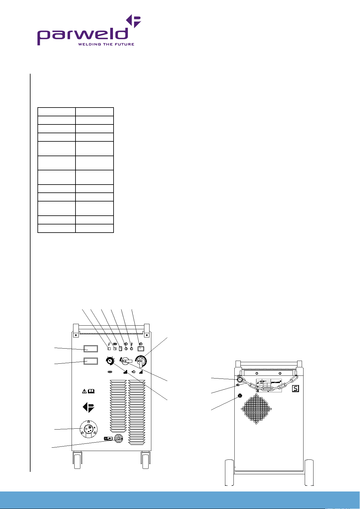
4.0 Description of controls
1. Gas purge button. Pressing this button allow gas to ow
through the welding torch and so allow checking of the gas ow
5
6
7
V
V
2T
1 0
4T
4
B
2
1
A
8
9
10
4
3
5
2
6
1
7
8
9
V
8
9
10
11
1 2
A
V
XTM 303C
3 4
before starting the welding process.
2. Wire inching button, allows the welding wire to be fed through
the torch without engergising the welding power.
3. 2T 4T, when in the 2T position the torch trigger will have a
momentary operation ie the welding operation will start when
the rigger is depressed and stop when it is released. In the 4T
position a short press and release of the trigger will start the
welding operation and a short press and release with stop the
operation. The 4T mode is ideal for long welds as it reduces
operator fatigue.
4. Mains input light This light illuminates when the mains power is
connected and the machine is switched on.
5. Fault light This light will illuminate when a fault or over
temperature condition has occurred. If this light illuminates
allow the machine to cool with the fan still running until it
extinguished. If the light does not go off when the power source
has cooled down then have the machine checked by a qualied
engineer.
6. On Off switch. The machine is switched off when the light (4) is
off and the fan is not running.
7. Fine Voltage selector switch. This switch is used to select the
require welding voltage each position of the switch represents
approximately 0.5V.
Do Not operate this switch while welding
8. Coarse Voltage selector switch. This switch is used to select the
require welding voltage each position of the switch represents
approximately 6V.
Do Not operate this switch while welding
9. Wire feed speed adjustment, controls the speed of wire feeding
from 0.8 to 24 m/min. Increasing the wire feed speed also has
the effect of increasing the welding current
10. Digital display for amperage (displayed real time)
11. Digital display for amperage (displayed real time)
12. Torch connector The Euro connector provided the external
connection for the welding torch.
13. Work return lead connection. This socket allows connection of
the work return lead to the front of the machine.
14. Mains input connection Input connection for the pre-installed
mains cable.
15. Gas cylinder restraint chain Use to secure the gas cylinder
when mounted on the rear of the machine
16. Shielding gas input connection 3/8 BSP male connection for the
shielding gas input.
17. Soft start adjustment which controls the acceleration of the wire
feed motor when the arc starts to reduce spatter and give a
14
15
3 PH
V
400V
GAS INPUT
XTM 303C
S No.
3~
60A/17V to 300A/29V
X 35% 60%
I2 300A 229A
PARWELD LTD,
U0 = 19~38V
U2 29V 25.5V
BEWDLEY BUSINESS PARK,
LONG BANK BEWDLEY,
WORCESTERSHIRE,
Rohs Compliant
16
6
12
13
www.parweld.com www.parweld.com
 Loading...