

XR914 Light Reactive Welding Helmet
Instruction Guide
MAINTENANCE
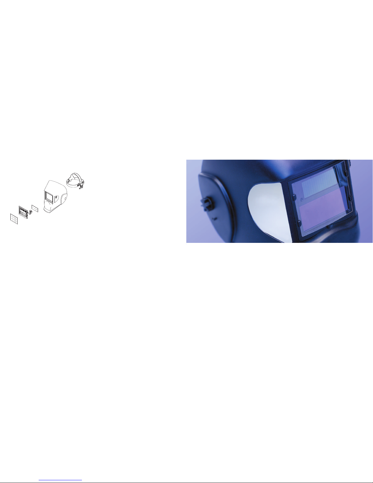
REPLACEMENT OF FRONT COVER LENS
• Remove the front cover lens by pulling outwards at the base of the
lens using the finger slot provided.
• Make sure the protective films are removed from the new cover lens.
• Place the new cover lens in the recess at the front of the helmet.
• Locate the cover lens under the 2 lugs at the left of the cartridge and
then flex the lens so that it can be inserted under the lugs on the right
hand side of the cartridge.
NOTE - Do not use the helmet without the cover lens in place.
REPLACEMENT OF INNER COVER LENS
• The welding inner cover lens is removed by pulling out the top edge.
• The new inner cover lens is assembled after the protective film is
removed. Locate one of the sides by inserting the edge under the
hook at the side and bend the lens in the middle part and locate the
lens under the hook at the other side.
REPLACEMENT OF WELDING FILTER
• Prise off the shade adjusting knob from the outside of the helmet and
unscrew the plastic locking nut below.
• From inside the helmet push inwards the two barbs on the left side of
the helmet to release them and push the cartridge forwards gently.
• The cartridge can now be removed from the front of the helmet.
FAULTFINDING
IRREGULAR DARKENING
• Headband has been set unevenly so the distance between the eyes
and the lens is different from the left to the right.
AUTO DARKENING FILTER DOES NOT DARKEN OR FLICKERS
• Front cover lens is soiled, clean or replace
• Photo sensors are dirty, wipe clean with a soft lint-free cloth.
• Welding current is too low, select the slow position on the filter and
ensure the view of the weld is unobstructed.
• Change to high sensitivity.
POOR VISION
• Ensure the cover lens and the filter cartridge are clean.
• Ensure the shade number is correct and adjust accordingly.
• Ensure ambient light is not too low.
XR914
Helmet Shell
XR914H
Complete Helmet
WARRANTY
We warrant to the purchaser that the product will be free from defects in
material and workmanship for the period of 18 months from the date of
the sale to the buyer. The manufacturers sole obligation under this
warranty is limited to making replacement or repairs, or to refund the
purchase price of the product with defects.
This warranty does not cover product malfunctions or damages, which
result from the product being tampered, misused or abused. The
operation instructions must be followed; failure to do will void the
warranty. The manufacturer is not responsible for any indirect damage,
which arises out of the use of the product.
INSPECTION
• Carefully inspect your Auto Darkening Welding Filter regularly.
• Cracked, pitted or scratched filter glass or cover lenses reduce vision
and seriously impair protection.
• These should be replaced immediately to avoid damage to the eyes.
• Inspect the complete helmet frequently and replace wor n or damaged
parts.
CLEANING
• Clean the helmet with mild soap and lukewarm water.
• Clean the welding filter with a clean lint-free tissue or cloth.
• Do not immerse in water.
• Do not use solvents.
XR420
Front Cover Lens
XR400
Cartridge
XR430
Inside Cover Lens
XR440
Adjustable Headband
XR410
Front Velcro
Cover
PARTS LIST
XR914 Light Reactive Welding Helmet
GENERAL INFORMATION
This XR914 Light Reactive Helmet will not protect against severe
impact hazards, such as fractured grinding wheels or abrasive discs,
explosive devices or corrosive liquids. Machine guards or eye splash
protection must be used when these hazards are present.
All light reactive welding filters are for use in Arc welding or cutting
applications. The unit is suitable for all Arc welding processes such as
MIG, MAG, TIG, SMAW, Plasma Arc, and Carbon Arc.
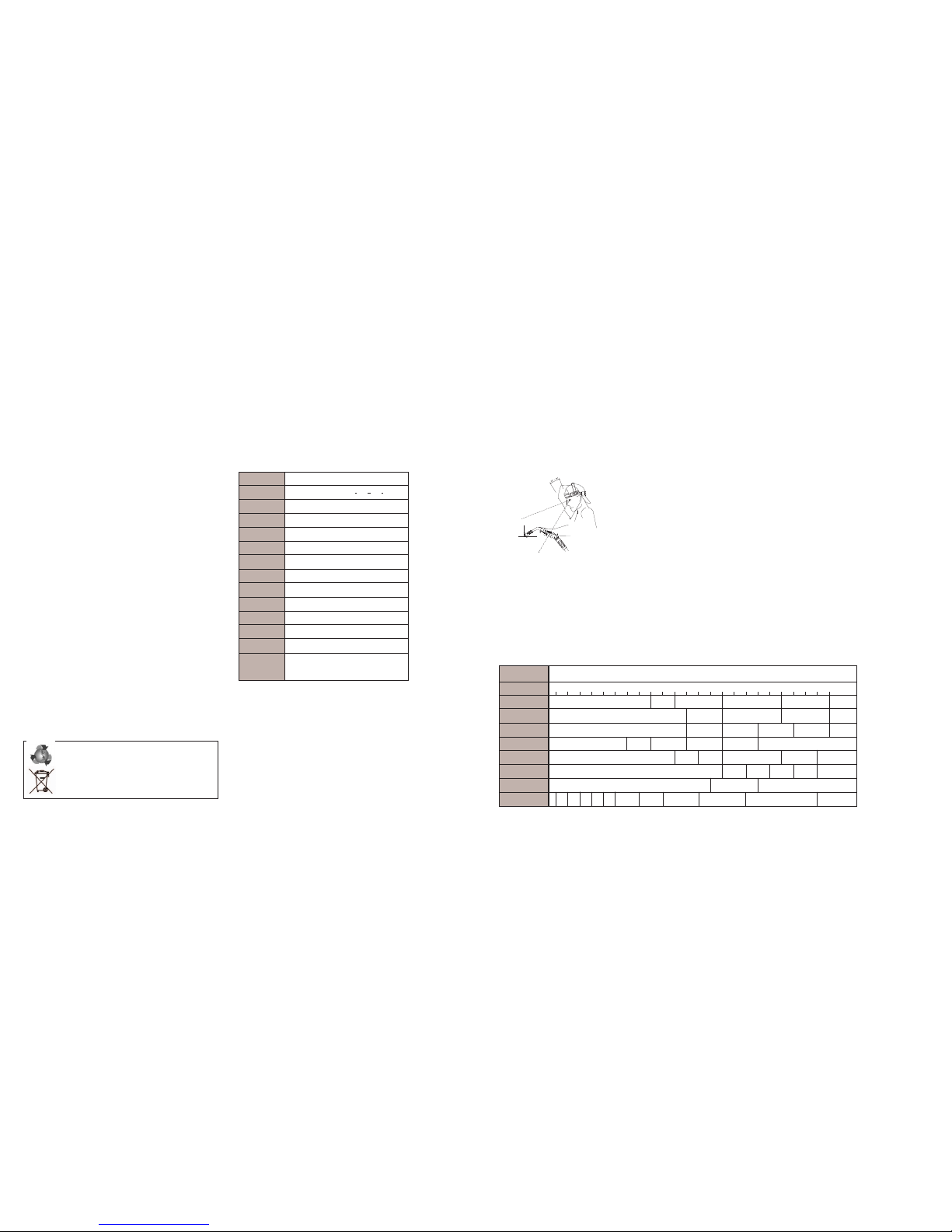
Use this helmet only for face and eye protection against harmful rays,
sparks and spatter from welding and cutting.
The XR914 Light Reactive Helmet is not suitable for “overhead”
welding applications, Laser welding or Laser cutting applications.
In the event of electronic failure, the welder remains protected against
UV and IR radiation according to Shade 16.
The light reactive welding filter should always be used with original
inner and outer cover lenses.
The manufacturer is not responsible for any modifications to the
welding filter or the use of the filter in any other manufacturer’s helmet.
Protection can be seriously impaired if unapproved modifications are
made.
WARNING
Please read and understand all instructions prior to using the
XR914 Light Reactive Welding Helmet.
Viewing Area 98mm x 44mm / 3.86” x 1.76”
Cartridge Size 122mm x 100mm x 9mm / 4 ” x 3 ”x 3 ”
UV/IR Protection Permanent Shade DIN16
Light State DIN Shade 4
Dark State DIN Shade 9 to 13 Variable
Power Supply
Solar cells with built in rechargeable battery
(estimated 6 year life)
Power On/Off Fully Automatic
Switching Time Light to dark 0.00004 seconds
Light to Dark
0.25 - 0.35 seconds - fast position
0.60 - 0.80 seconds - slow position
Operating Temp -5ºC to +70ºC (23ºF to 131ºF)
Storage Temp -20ºC to +70ºC (-4ºF to -158ºF)
Helmet Material HighImpact Polyamide Nylon
TotalWeight 430g
Minimum
Amperage 40 Amps
Required
TECHNICAL SPECIFICATION
DO
Ensure the front cover lens is fitted before use and remove protective
film.
Ensure that the lens is clean and there is no dirt or spatter covering the
2 sensors at the front of the filter cartridge.
Inspect all parts for signs of wear or damage. Any scratched or
cracked parts should be replaced prior to use.
DON’T
Never place the helmet on a hot surface.
Never open or tamper with the filter cartridge.
OPERATION
1. ADJUST THE WELDING HELMET ACCORDING TO YOUR
INDIVIDUAL REQUIREMENTS
The headband should be adjusted both in diameter and height. The angle
between face and helmet should also be adjusted and is recommended
to be 10º - 12º.
2. ON/OFF
The solar unit automatically switches on when exposed to light.
3. SELECT THE SHADE NUMBER
Five different shade numbers, 9, 10, 11, 12 and 13, are available in the
dark state.
The shade number can be selected by turning the shade on the side of
the helmet
The set shade is indicated by the arrow on the switch.
4. SELECT DELAY TIME
By moving the selector switch on the rear of the cartridge the time taken
for the lens to lighten after welding can be altered.
FAST
The lens will lighten after welding in 0.25 to 0.35 second dependant
upon ambient temperature and shade set. This setting is ideal for tack
welding or production welding with short welds.
SLOW
The lens will lighten in 0.6 to 0.8 seconds dependant upon the
ambient temperature and set shade. This setting is ideal for welding at
high amperages where there is an after glow from the weld.
5. SELECT SENSITIVITY
By moving the selector switch on the rear of the cartridge the sensitivity
to ambient light changes can be altered.
LOW
Suitable for high amperage welding and welding in bright sunlit
conditions.
HIGH
Suitable for low amperage welding and use in poor light conditions.
Suitable for use with steady arc process such as Tig welding.
RECOMMENDED SHADE NUMBERS
WELDING PROCESS 0.5 1 2.5 5 10 15 20 30 40 60 80 100 125 150 175 200 225 250 275 300 350 400 450 500
Covered Electrode Shade 9 Shade 10 Shade 11 Shade 12 Shade13 14
MIG Plate Welding Shade 10 Shade 11 Shade 12 Shade 13 14
MIG Sheet Metal Shade 10 Shade 11 Shade 12 Shade 13 Shade 14 15
TIG Shade 9
Shade 10 Shade 11 Shade 12 Shade 13 Shade 14
MAG Shade 10 Shade 11 Shade 12 Shade 13 Shade 14 Shade15
Ar
c Gouging Shade 10 11 12 13 14 15
Plasma Cutting Shade 11 Shade 12 Shade 13
Plasma W
elding
4
5 6 7 8 9 10 11 12 13 14 15
CURRENT AMPERES
5
5
116
6
115
5
116
6
1
1
2
2
Please dispose of packaging for the product in a responsible manner. It is suitable
for recycling. Help to protect the environment, take the packaging to the local
amenity tip and place into the appropriate recycling bin.
Never dispose of electrical equipment or batteries in with your domestic waste.
If your supplier offers a disposal facility please use it or alternatively use your local
amenity tip and dispose in the correct manner. This will allow the recycling of raw
materials and help protect the environment.
 Loading...