

TR003 Trolley Assembly Instructions
Sheet 1 of 3
7
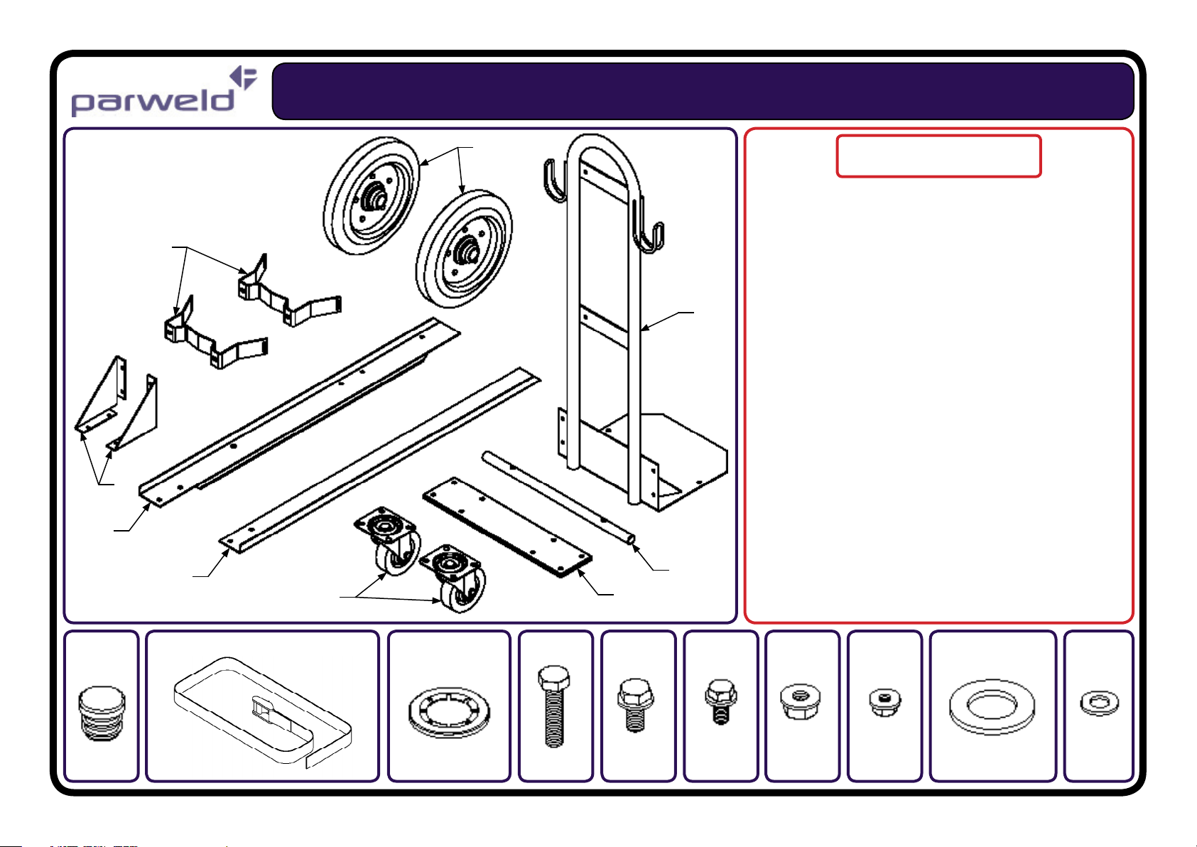
1) Tubular Mounting Frame (Gas Bottle) x 1
6
1
4
3
2
9
5
8
2) Angle Runner (RH) x 1
3) Angle Runner (LH) x 1
4) Mounting Frame Gusset Plate x 2
5) Front Mounting Plate (Castors) x1
6) Support Bracket (Gas Bottle) x 2
7) Wheel (Ø250) x 2
8) Wheel Axle x 2
9) Swivel Castor (Ø100) x 2
10) Plastic End Cap (Ø20) x 2
11) 25mm x 1560mm Fabric Strap With Buckle x 1
12) 25mm x 1130mm Fabric Strap With Buckle x 1
13) Retaining Washer (Ø20) x 2
14) M8 x 35 Hex Set Screw x 2
15) M8 x 16 Hex Set Washer Head Screw x 8
16) M6 x 12 Hex Set Washer Head Screw x 12
17) M8 Hex Washer Head Nut x 10
18) M6 Hex Washer Head Nut x 12
19) M20 Flat Washer x 2
20) M8 Flat Washer x 2
Trolley Parts List
10
11 & 12 13 14 16 17 18 19 2015

TR003 Trolley Assembly Instructions
Sheet 2 of 3
FIG 1
Affix the plastic end caps (10) in the wheel
axle ends (8) prior to assembly. Take the
tubular mounting frame (1) and the angle
runners (2 & 3) along with the wheel axle.
Align the mounting holes as shown in FIG 1
and secure using the M8x35 screws (14), flat
washers (20) and nuts (17) supplied.
Note: Do not fully tighten the mounting screws
until the gusset plates have been assembled
(see FIG 5).
FIG 2
Take the front mounting plate (5)
and the swivel castors (9) and assemble with the angle runners. Align
the mounting holes as shown in
FIG 2 and secure using the M8x16
screws (15) and nuts (17) supplied.
Note: Do not fully tighten the fixing
screws until the gusset plates have
been assembly (see FIG 5).
FIG 3
FIG 4
Next assemble the wheels on the axle. First
slide the M20 washers (19) on both ends of
the axle. Then slide the wheels (7) onto the
axle and up to the washers. The retaining
washers (13) can then applied to secure the
wheels in position. FIG 4 shows the final
assembly.

TR003 Trolley Assembly Instructions
Sheet 3 of 3
FIG 5
FIG 6
FIG 6
FIG 7
FIG 8
Assemble the gusset plates using the M6x12 screws
(16) and nuts (18) as shown in FIG 5. A complete
gusset plate assembly should look like FIG 6.
Note: The other fixing screws in FIG 1 & 2 can now
be tightened to complete the lower trolley assembly.
Finally the gas bottle support brackets
can be fixed using the remaining M6x12
screws (16) and nuts (18) as shown in
FIG 7. The straps (11 & 12) can then be
laced through the bracket slots with the
longer strap at the bottom (see FIG 8).
Complete TR003 trolley assembly
as shown above.
 Loading...