

Partner Tech International PT-6200 Service Manual
PT-6200
Service Manual


i
Copyright
This publication, including all photographs, illustrations and software, is protected under international
copyright laws, with all rights reserved. Neither this manual, nor any of the material contained herein, may be
reproduced without written consent of the author.
Disclaimer
The information in this document is subject to change without notice. The manufacturer makes no representa-
tions or warranties with respect to the contents hereof and specically disclaims any implied warranties of
merchantability or tness for any particular purpose. The manufacturer reserves the right to revise this publi-
cation and to make changes from time to time in the content hereof without obligation of the manufacturer to
notify any person of such revision or changes.
Trademark recognition
All product names used in this manual are the properties of their respective owners and are acknowledged.
Federal Communications Commission (FCC)
This equipment has been tested and found to comply with the limits for a Class A digital device, pursuant to
Part 15 of the FCC Rules. These limits are designed to provide reasonable protection against harmful interference in a residential installation. This equipment generates, uses, and can radiate radio frequency energy
and, if not installed and used in accordance with the instructions, may cause harmful interference to radio
communications. However, there is no guarantee that interference will not occur in a particular installation. If
this equipment does cause harmful interference to radio or television reception, which can be determined by
turning the equipment off and on, the user is encouraged to try to correct the interference by one or more of
the following measures:
Reorient or relocate the receiving antenna.
Increase the separation between the equipment and the receiver.
Connect the equipment onto an outlet on a circuit different from that to which the receiver is connected.
Consult the dealer or an experienced radio/TV technician for help.
Shielded interconnect cables and a shielded AC power cable must be employed with this equipment to ensure
compliance with the pertinent RF emission limits governing this device. Changes or modications not expressly approved by the system’s manufacturer could void the user’s authority to operate the equipment.
Declaration of conformity
This device complies with part 15 of the FCC rules. Operation is subject to the following conditions:
This device may not cause harmful interference, and
This device must accept any interference received, including interference that may cause undesired operation.

ii
About this manual
The service manual provides service information for the PT-6200. This manual is designed to help train
service personnel to locate and x failing parts on the machine.
This manual consists of the following sections:
Chapter 1 Getting Started:
This section covers unpacking and checking the package contents, and identifying components.
Chapter 2 BIOS Setup Utility:
The BIOS chapter provides information on navigating and changing settings in the BIOS Setup
Utility.
Chapter 3 Installing Drivers and Software:
This chapter provides information on installing drivers for supported operating systems.
Chapter 4 Locating the Problem:
Refer to this chapter to locate the failing part or cause of the problem that requires servicing.
Chapter 5 Replacing Field Replaceable Units (FRUs):
This chapter provides drawings and instructions to replace all FRUs.
Appendix: Optional Components, Exploded Diagram, and Parts List:
The appendix includes an exploded diagram of the machine and the parts list and order number for
each part.
Safety information
Before servicing the machine, read the safety information under “Safety and precautions” on page 53.
Revision history
Version 1.0, May 2008

iii
TABLE OF CONTENTS
CHAPTER 1 GETTING STARTED ................................................ 1
Unpacking the machine .................................................................................1
Identifying components .................................................................................2
CHAPTER 2 BIOS SETUP ............................................................ 5
About the Setup Utility ...................................................................................5
Entering the Setup Utility ..........................................................................6
BIOS navigation keys ................................................................................6
Using BIOS ...............................................................................................7
Standard CMOS features ...............................................................................8
Advanced BIOS Features ............................................................................10
Advanced Chipset Features .........................................................................12
Integrated Peripherals ..................................................................................14
► OnChip IDE Device .............................................................................15
► OnChip PCI Device .............................................................................16
► SuperIO Device ...................................................................................17
Power Management Setup...........................................................................18
PnP/PCI Congurations ...............................................................................20
► IRQ Resources ....................................................................................21
PC Health Status..........................................................................................22
Frequency/Voltage Control...........................................................................23
Other BIOS Options .....................................................................................24
CHAPTER 3 INSTALLING DRIVERS AND SOFTWARE ............ 27
Driver auto installation..................................................................................27
Intel Chipset Driver.......................................................................................28
Intel Chipset Graphics Driver .......................................................................30
Audio driver ..................................................................................................32
LAN Driver ....................................................................................................34
Touch Screen Driver.....................................................................................36
Calibrating the touchscreen .....................................................................39
CHAPTER 4 LOCATING THE PROBLEM .................................. 41
General checkout guidelines ........................................................................41
Cash drawer checkout .................................................................................41
LCD symptoms .............................................................................................42
Touch screen symptoms ..............................................................................43

iv
Power symptoms..........................................................................................43
Network symptoms .......................................................................................43
USB symptoms ............................................................................................44
Peripheral-device symptoms ........................................................................44
Boot symptoms ............................................................................................44
Mainboard jumper settings ...........................................................................45
Setting a jumper ...........................................................................................45
Mainboard jumpers ......................................................................................46
Mainboard connectors..................................................................................47
Inverter connectors ......................................................................................48
CHAPTER 5 REPLACING FIELD REPLACEABLE UNITS (FRUs)
..................................................................................................... 49
Safety and precautions ................................................................................49
Before you begin ..........................................................................................50
Replacing parts ............................................................................................50
Front Panel...................................................................................................51
MSR .............................................................................................................51
Mainboard ....................................................................................................52
Hard drive.....................................................................................................53
Thermal Printer ............................................................................................54
Customer Display .........................................................................................55
Speaker ........................................................................................................55
LCD Panel ....................................................................................................56
Inverter .........................................................................................................56
Touch Panel .................................................................................................57
Memory ........................................................................................................57
Battery ..........................................................................................................57
APPENDIX PART LIST AND SPECIFICATION ........................... 59
Part list for White PT-6200 ..........................................................................60
Part list for Charcoal PT-6200 .....................................................................61
Specications ...............................................................................................62

v
LIST OF FIGURES
Figure 1.1 Unpacking the machine ......................................................... 1
Figure 1.2 Front-right view of the machine.............................................. 2
Figure 1.3 Rear view ............................................................................... 3
Figure 1.4 PT-6200 I/O connectors ......................................................... 4
Figure 3.1 Main BIOS menu.................................................................... 6
Figure 3.2 Standard CMOS Features menu ........................................... 8
Figure 3.3 IDE Primary Master submenu ................................................ 9
Figure 3.4 Advanced BIOS Features menu .......................................... 10
Figure 3.5 Advanced Chipset Features menu ....................................... 12
Figure 3.6 Integrated Peripherals menu................................................ 14
Figure 3.7 VIA OnChip IDE Device submenu ....................................... 15
Figure 3.8 VIA OnChip PCI Device submenu ....................................... 16
Figure 3.9 SuperIO Device submenu .................................................... 17
Figure 3.10 Power Management Setup menu ...................................... 18
Figure 3.11 PnP/PCI Conguration menu ............................................. 20
Figure 3.12 IRQ Resources submenu................................................... 21
Figure 3.13 PC Health Status menu ..................................................... 22
Figure 3.14 PC Health Status menu ..................................................... 23
Figure 4.1 Connecting a cash drawer ................................................... 42
Figure 4.2 PT-6200 mainboard jumpers................................................ 46
Figure 4.3 PT-6200 mainboard connectors ........................................... 47
Figure 4.4 Inverter connectors .............................................................. 48
Figure 6.1 Exploded diagram main parts .............................................. 59
Figure 6.2 Exploded diagram MSR parts .............................................. 59

vi

1
CHAPTER 1
GETTING STARTED
This chapter describes how to unpack and identifying components on the device. The following topics are
described.
Unpacking the machine on page • 1
Identifying components on page • 2
Unpacking the machine
It is a good idea to save the packaging materials and shipping box in case that machine needs to be returned
for service. Please un-pack and re-pack the machine terminal as shown in Figure 1.1.
Figure 1.1 Unpacking the
machine
2 C H A P T E R 1 G E T T I N G S TA R T E D
Identifying components
This section describes the parts and connectors on the machine.
Front-right view
1 52
Figure 1.2 Front-right view of the machine.
Component Description
1 Power Button
2 10.4-inch TFT LCD; 5-wire Resistive touch
3 IO Panel
4 LED Power Indicator
5 Tripple-track MSR
3 4
3
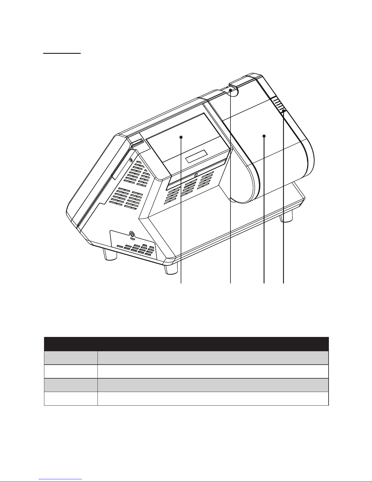
Rear view
1
Figure 1.3 Rear view
Component Description
1 2x20 VFD customer display
2 Printer paper exit
3 80mm thermal receipt printer
4 Printer button
32 4

4 C H A P T E R 1 G E T T I N G S TA R T E D
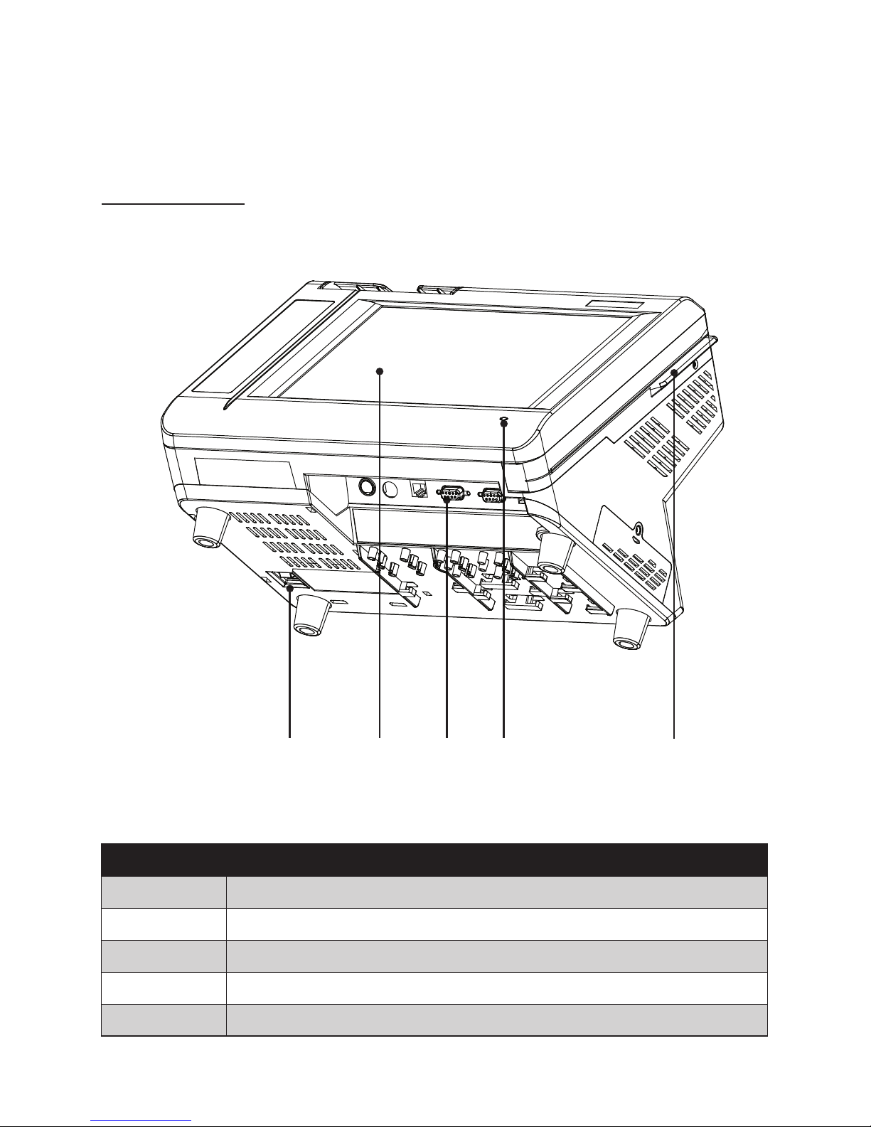
I/O connectors
Figure 1.4 PT-6200 I/O connectors
4
1 2 3
5 6 7 8 9
Connector Description
1 COM4 port
2 COM2 port
3 LAN port (RJ-45)
4 12V power connector
5 PS/2 keyboard port
6 RJ-11 cash drawer port
7 COM3 port
8 COM1 port
9 USB ports

5
CHAPTER 2
BIOS SETUP
The primary function of the BIOS (Basic Input and Output System) is to identify and initiate component
hardware. The BIOS parameters are stored in non-volatile BIOS memory (CMOS). CMOS contents don’t get
erased when the computer is turned off. The following topics are described in this chapter.
About the Setup Utility on page • 5
Standard CMOS features on page • 8
Advanced BIOS Features on page 1• 0
Advanced Chipset Features on page 1• 2
Integrated Peripherals on page 1• 4
Power Management Setup on page 1• 8
PnP/PCI Congurations on page 2• 0
PC Health Status on page 2• 2
Frequency/Voltage Control on page 2• 3
Other BIOS Options on page 2• 4
About the Setup Utility
The BIOS Setup Utility enables you to congure the following items:
Hard drives, diskette drives, and peripherals •
Video display type and display options •
Password protection from unauthorized use•
Power management features •
This Setup Utility should be used for the following:
When changing the system conguration •
When a conguration error is detected and you are prompted to make changes to the Setup Utility •
When trying to resolve IRQ conicts •
When making changes to the Power Management conguration •
When changing the User or Supervisor password •
6 C H A P T E R 2 B I O S S E T U P
Entering the Setup Utility
When you power on the system, BIOS enters the Power-On Self Test (POST) routines. POST is a series of
built-in diagnostics performed by the BIOS. After the POST routines are completed, the following message
appears:
Press DEL to enter SETUP
Press the delete key <Delete> to access the Award BIOS Setup Utility:
BIOS navigation keys
The BIOS navigation keys are listed below.
Key Function
←↑↓→ Scrolls through the items on a menu
+/–/PU/PD Modies the selected eld’s values
Esc Exits the current menu
F1 Displays a screen that describes all key functions
F5 Loads previously saved values to CMOS
F6 Loads a minimum conguration for troubleshooting
F7 Loads an optimum set of values for peak performance
F10 Saves the current conguration and exits Setup
Shift + F2 Changes the color of the BIOS menu
Phoenix - AwardBIOS CMOS Setup Utility
Standard CMOS Feature ►
Advanced BIOS Features ►
Advanced Chipset features ►
Integrated Peripherals ►
Power Management Setup ►
PnP/PCI Congurations ►
PC Health Status ►
Frequency/Voltage Control ►
Load Fail-Safe Defaults
Load Optimized Defaults
Set Supervisor Password
Set User Password
Save & Exit Setup
Exit Without Saving
Esc : Quit
F10 : Save & Exit Setup
↑ ↓ → ← : Select Item
Time, Date, Hard Disk Type...
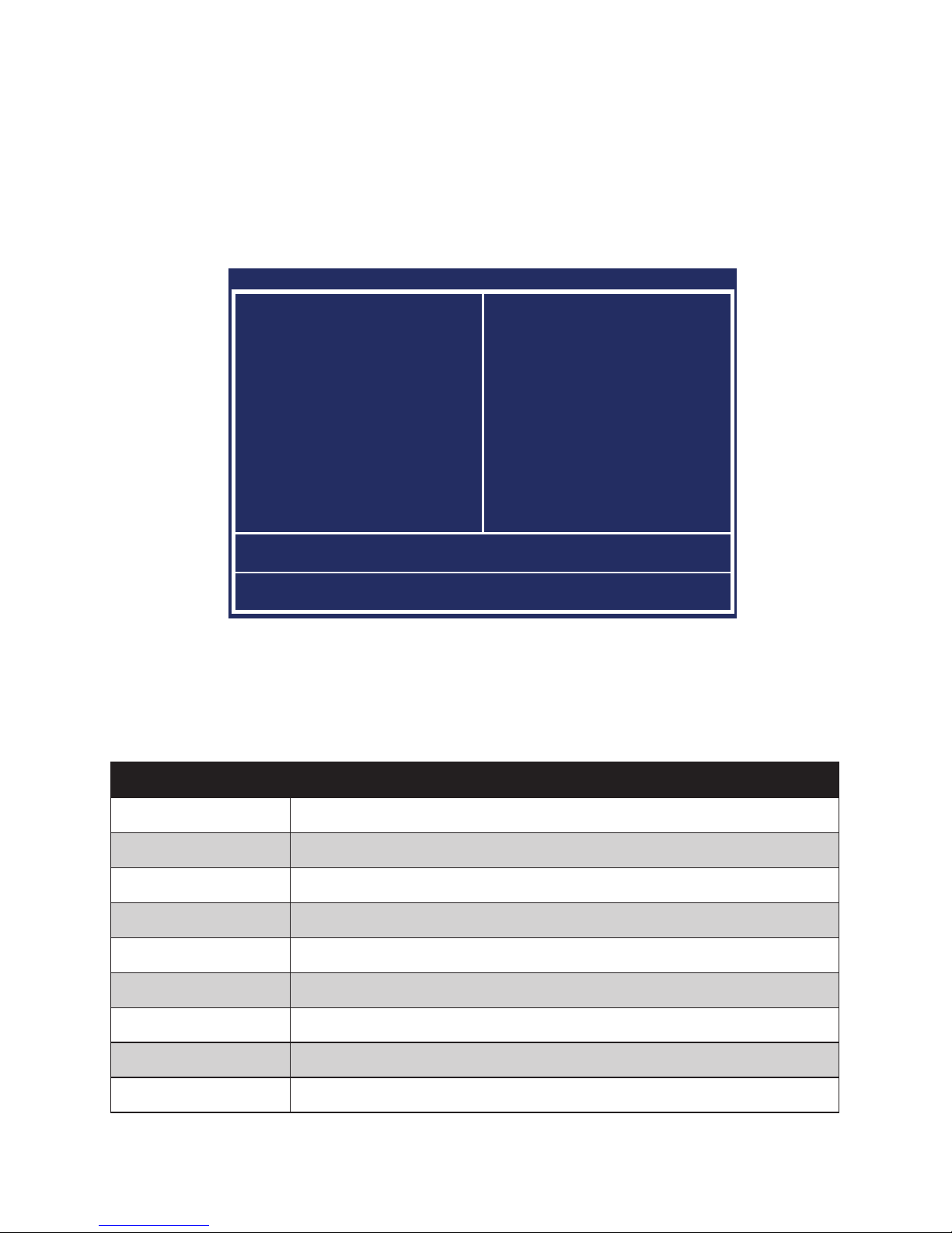
Main BIOS menuFigure 3.1

7
Using BIOS
When you start the Setup Utility, the main menu appears. The main menu of the Setup Utility displays a list
of the options that are available. A highlight indicates which option is currently selected. Use the cursor arrow
keys to move the highlight to other options. When an option is highlighted, execute the option by pressing
<Enter>.
Some options lead to pop-up dialog boxes that prompt you to verify that you wish to execute that option.
Other options lead to dialog boxes that prompt you for information.
Some options (marked with a triangle ►) lead to submenus that enable you to change the values for the option. Use the cursor arrow keys to scroll through the items in the submenu.

8 C H A P T E R 2 B I O S S E T U P
Standard CMOS features
Selecting Standard CMOS Features on the main menu displays the following menu:
Date and Time
The Date and Time items show the current date and time held by the machine. If you are running a Windows
OS, these items are automatically updated whenever you make changes to the Windows Date and Time
Properties utility.
Video
These elds is used to select the default video device. The default setting is EGA/VGA.
Halt On
This item denes the operation of the system POST (Power On Self Test) routine. You can use this item to
select which types of errors in the POST are sufcient to halt the system.
Base Memory, Extended Memory, and Total Memory
These items are automatically detected by the system at start up time. These are display-only elds. You cannot make changes to these elds.
Base Memory – This eld displays the amount of conventional memory detected by the system during •
boot.
Extended Memory – This eld displays the amount of extended memory detected by the system dur-•
ing boot.
Total Memory – This eld displays the total amount of memory (Base and Extended) detected by the •
system during boot.
Standard Figure 3.2
CMOS Features menu
Phoenix - AwardBIOS CMOS Setup Utility
Standard CMOS Features
Date (mm:dd:yy) Sat, Apr 4 2008
Time (hh:mm:ss) 8 : 33 : 14
IDE Channel 0 Master ► [ None]
IDE Channel 1 Slave ► [ None]
IDE Channel 2 Master ► [WDC WD800JD-60LSA5]
IDE Channel 3 Slave ► [ None]
Video [EGA/VGA]
Halt On [All , But Keyboard]
Base Memory 640K
Extended Memory 409472K
Total Memory 490496K
Item Help
↑↓→←:Move Enter:Select +/-/PU/PD:Value F10:Save ESC:Exit F1:General Help
F5:Previous Values F6:Fail-Safe Defaults F7:Optimized Defaults

9
IDE Channel 0/1/2/3 Master/Slave
This eld is used to congure the IDE hard drive installed in the system. Move the cursor to highlight the IDE
Primary/Secondary Master/Slave elds and press <Enter>. The IDE Primary Master submenu opens:
IDE HDD Auto-Detection
Press Enter while this item is highlighted if you want the Setup Utility to automatically detect and congure a
hard disk drive on the IDE channel.
IDE Channel 0/1/2/3 Master/Slave
If you leave this item at Auto, the system will automatically detect and congure any IDE devices it nds. If
it fails to nd a hard disk, change the value to Manual and then manually congure the drive by entering the
characteristics of the drive in the elds described below:
Capacity – displays the capacity of the HDD in megabytes (MB). •
Cylinder – indicates the number of cylinders that the HDD has. A cylinder is the sum total of all tracks •
that are in the same location on every disk surface.
Head – displays the number of heads in the HDD. A head is a device that reads and writes data on the •
hard disk.
Precomp – displays the track where precompensation is initiated. Precompensation is a feature •
whereby the HDD uses a stronger magnetic eld to write data in sectors that are closer to the center
of the disk. In CAV recording, in which the disk spins at a constant speed, the sectors closest to the
spindle are packed tighter than the outer sectors.
Landing Zone – displays the location of the safe non-data area on a hard disk that is used for parking •
the read/ write head.
Sector – displays the number of sectors available on the HDD. A sector is the smallest unit of storage •
space on a disk.
Access Mode
This item denes special ways that can be used to access IDE hard disks such as LBA (Large Block Addressing). Leave this value at Auto and the system will automatically decide the fastest way to access the hard disk
drive.
NOTE
If you are setting up a new hard disk drive that supports LBA mode,
more than one line will appear in the parameter box. Choose the line that
lists LBA for an LBA drive.
Phoenix - AwardBIOS CMOS Setup Utility
IDE Channel 0 Master
IDE HDD Auto-Detection [Press Enter]
IDE Channel 0 Master [Auto]
Access Mode [Auto]
Capacity 40022 MB
Cylinder 19158
Head 16
Precomp 0
Landing Zone 19157
Sector 255
Item Help
↑↓→←:Move Enter:Select +/-/PU/PD:Value F10:Save ESC:Exit F1:General Help
F5:Previous Values F6:Fail-Safe Defaults F7:Optimized Defaults
IDE Primary Figure 3.3
Master submenu

10 CHAPTER 2 BIOS SETUP
Advanced BIOS Features
Selecting Advanced BIOS Features on the main menu opens up this screen:
First/Second/Third Boot Device
The BIOS loads the operating system from the disk drives in the sequence selected in these three elds. The
default setting is USB-0/Disabled/Disabled.
Boot Other Device
When enabled, the system searches all other possible locations for an operating system if it fails to nd one in
the devices specied under the First, Second, and Third boot devices. The default setting is Enabled.
Security Option
Select whether the password is required every time the system boots or only when you enter setup. The
default setting is Setup.
Option Description
System
The system will not boot and access to Setup will be denied if the correct password is not
entered at the prompt.
Setup
The system will boot, but access to Setup will be denied if the correct password is not
entered at the prompt.
APIC Mode
This item is used to activate the ACPI (Advanced Conguration and Power Management Interface) Mode.
The default setting is Enabled.
IMPORTANT
ACPI is a power management specication that makes hardware
status information available to the operating system. ACPI enables a
PC to turn its peripherals on and off for improved power management.
It also allows the PC to be turned on and off by external devices, so
that mouse or keyboard activity wakes up the machine.
Phoenix - AwardBIOS CMOS Setup Utility
Advanced BIOS Features
First Boot Device [USB-0]
Second Boot Device [Disabled]
Third Boot Device [Disabled]
Boot Other Device [Enabled]
Security Option [Setup]
APIC Mode [Enabled]
MPS Version Control For OS[1.4]
Full Screen LOGO Show [Disabled]
Small Logo(EPA) Show [Enabled]
Item Help
↑↓→←:Move Enter:Select +/-/PU/PD:Value F10:Save ESC:Exit F1:General Help
F5:Previous Values F6:Fail-Safe Defaults F7:Optimized Defaults
Advanced BIOS Figure 3.4
Features menu

11
MPS Version Control For OS
This eld allows you to select the MPS (Multi-Processor Specication) version to match the operating system. To nd out which version to use, consult the vendor of your operating system. The default setting is 1.4.
OS Select For DRAM > 64 MB
This item is only required if you have installed more than 64 MB of memory and you are running the OS/2
operating system. Otherwise, leave this item at the default. The default setting is Non-OS2.
Full Screen LOGO Show
This item enables you to show the full screen logo on the bootup screen. The default setting is Disabled.
Small Logo(EPA) Show
This item enables you to show the company logo on the bootup screen. The default setting is Enabled.

12 CHAPTER 2 BIOS SETUP
Advanced Chipset Features
This option displays critical timing parameters of the mainboard. Leave the items on this menu at their default
settings unless you are very familiar with the technical specications of the system hardware. If you change
the values incorrectly, you may introduce fatal errors or recurring instability into the system.
Advanced Chip-Figure 3.5
set Features menu
Phoenix - AwardBIOS CMOS Setup Utility
Advanced Chipset Features
DRAM Timing Selectable By SPD x
CAS Latency Time 2.5 x
Active to Precharge Delay 7 x
DRAM RAS# to CAS# Delay 3 x
DRAM RAS# Precharge 3 x
DRAM Data Integrity Mode Non-ECC
System BIOS Cacheable [Enabled]
Video BIOS Cacheable [Enabled]
Memory Hole At 15M-16M [Disabled]
Delayed Transaction [Enabled]
Delay Prior to Thermal [16 Min]
AGP Aperture Size (MB) [64]
** On-Chip VGA Setting **
On-Chip Frame Buffer Size [16MB]
Item Help
↑↓→←:Move Enter:Select +/-/PU/PD:Value F10:Save ESC:Exit F1:General Help
F5:Previous Values F6:Fail-Safe Defaults F7:Optimized Defaults
DRAM Timing Selectable
Set this to the default value to enable the system to automatically set the SDRAM timing by SPD (Serial Presence Detect). SPD is an EEPROM chip on the DIMM module that stores information about the memory chips
it contains, including size, speed, voltage, row and column addresses, and manufacturer. The default value is
By SPD.
CAS Latency Time
When the DRAM Timing Selectable is set to [Manual], this eld is adjustable. When synchronous DRAM is
installed, the number of clock cycles of CAS latency depends on the DRAM timing. The default value is 2.5.
Active to Precharge
When the DRAM Timing Selectable is set to [Manual], this eld is adjustable. This item controls the number
of cycles for Row Address Strobe (RAS) to be allowed to precharge. If insufcient time is allowed for the
RAS to accumulate its charge before DRAM refresh, refresh may be incomplete and DRAM may fail to retain
data. This item applies only when synchronous DRAM is installed in the system. The default value is 7.
DRAM RAS# to CAS# Delay
When the DRAM Timing Selectable is set to [Manual], this eld is adjustable. This eld lets you insert a timing delay between the CAS and RAS strobe signals, used when DRAM is written to, read from, or refreshed.
Fast gives faster performance; and Slow gives more stable performance. This eld applies only when syn-
chronous DRAM is installed in the system. The default value is 3.
DRAM RAS# Precharge
When the DRAM Timing Selectable is set to [Manual], this eld is adjustable. This setting controls the number of cycles for Row Address Strobe (RAS) to be allowed to precharge. If insufcient time is allowed for the
RAS to accumulate its charge before DRAM refresh, refresh may be incomplete and DRAM may fail to retain
data. This item applies only when synchronous DRAM is installed in the system. The default value is 3.
DRAM Data Integrity Mode
This item detects whether the installed DRAM has error correction. This parameter is non-congurable.

13
System/Video BIOS Cacheable
These items allow the video and/or system to be cached in memory for faster execution. We recommend that
you leave these items at the default value. The default setting is Enabled/Enabled.
Memory Hole At 15M-16M
This item can be used to reserve memory space for some ISA expansion cards that require it. The default setting is Disabled.
Delayed Transaction
This feature controls the operation of that embedded 32-bit posted write buffer. Select [Enabled], all PCI-toISA writes are buffered and the PCI bus is released after writing to the buffer. Select [Disabled], the PCI bus
will bypass the write buffer and write directly to the ISA bus. The default setting is Enabled.
Delay Prior to Thermal
When the CPU temperature reaches a factory preset level, a thermal monitoring mechanism will be enabled
following the appropriate timing delay specied in this eld. With the thermal monitoring enabled, clock
modulation controlled by the processor’s internal thermal sensor is also activated to keep the processor within
allowable temperature limit. The default setting is 16 Min.
AGP Aperture Size (MB)
This eld allows you to select how much system RAM can be allocated to AGP for video purposes. The aperture is a portion of the PCI memory address range dedicated to graphics memory address space. Host cycles
that hit the aperture range are forwarded to the AGP without any translation. The default setting is 64.
** On-Chip VGA Setting **
The following items allow you to congure the settings about On-Chip VGA.
On-Chip Frame Buffer Size
This item is used to select the video frame buffer size. The default setting is 16MB.
 Loading...