

Page 1
Handheld Termanal
Manual
PARTNER TECH CORPORATION
Please carefully read the operating instructions
Before using the product,
Page 2

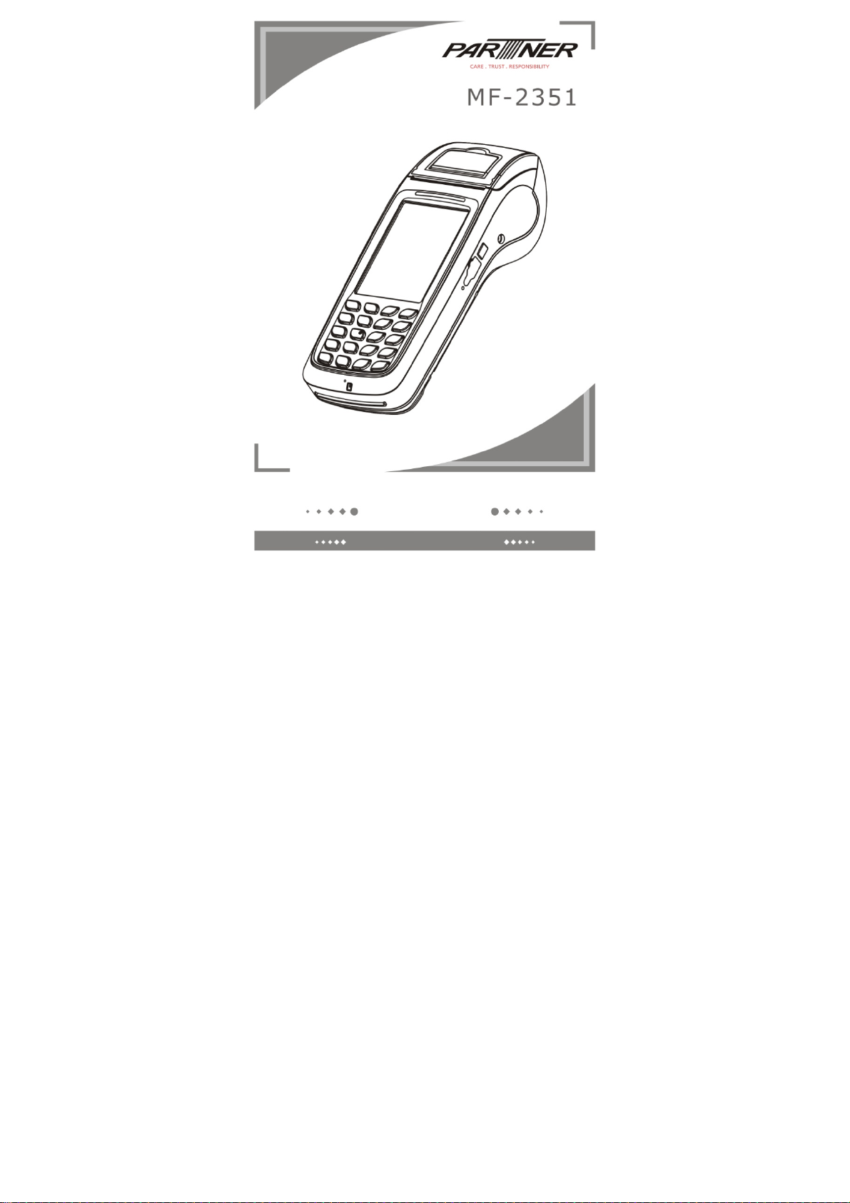
NO.1
Features
Specifications
Processor
Operating
System
Memory
Flash
Display
Key
Specification
Magnetic Card
IC card reader
SAM card
Expansion Slot
USB
RS232
Printer
Audio
Vibration
Battery
Power
Communication
Interface(built-in)
Secure
Performance
Specification
Physical
Specification
Package
Contents
Communication
Camera
Contactless reader
Bar code
Scanner
Fingerprint
Certification
Description
TI Cortex A8 AM3715,1GHz
WinCE 6.0
DDR2,2Gb(256M);NAND Flash,4GB(512M);
3.5inch 240×320 Pixels / 262,000 Color,
Support touch and stylus input
Alpha & numeric Keys(Total 20 Hardware Keys)
Triple Track (track 1, 2, & 3)
EMV/PBOC2.0 L1&L2; ISO 7816
2
Mini SD Card Slot
1 USB (OTG)
1 USB(RS232)
High Speed, High resolution, thermal printer
speaker (mono)x1, microphonex1
support
Rechargeable Battery: DC7.4V/2000mAh
Power Adapter:Output voltage DC9V/3A ;
Input voltage 100~240V, 50/60Hz
1 SIM slot
Processor MAXQ1850
Operating System VOS
Dimension (mm):208 (L) x 85.5(W) x 53(D) mm
Weight:500g
Operating Temperature:0°C to 40°C
USB Cable, Stylus Pen,AC adapter,
Rechargeable Battery
WCDMA,
3.1 M Pixel
ISO 14443 A/B/NFC,Contactless EMV
1D or 2D
CCC, EMV/PBOC2.0 Levle1&Level2
qPBOC2.0 L1 L2
Security Certificate for PIN Entry Device
China UnionPay Network Access license
(Diameter30mm,Width58mm)
Bluetooth 2.1+EDR,
WIFI 802.11 b/g
,GPRS,GPS
Page 3
NO.2
1 MF=2351
2 Power Adapter
3 AC Power Cord
NO.3
Packaging / Packing List
1 piece
1 piece
1 piece 6
4
5 Thermal Print Paper 1 roll(optional)
Product Description
USB Line
Rechargeable Battery
1 piece
1 piece
Description:
1
RFID
Cutter
Touch Pannel 3.5 inch 240 × 320 pixels / 262,000 color
Keypad
Printer Cover Lever: Open the Printer Cover;
Printer Paper Thermal paper with 58mm in width and 30 mm diameter;
RFID reading area;
Cut paper, tear printer paper by tilting at about 45 degrees
from left to right along the cutter
Alpha & numeric keys(Total 20 hardware keys)
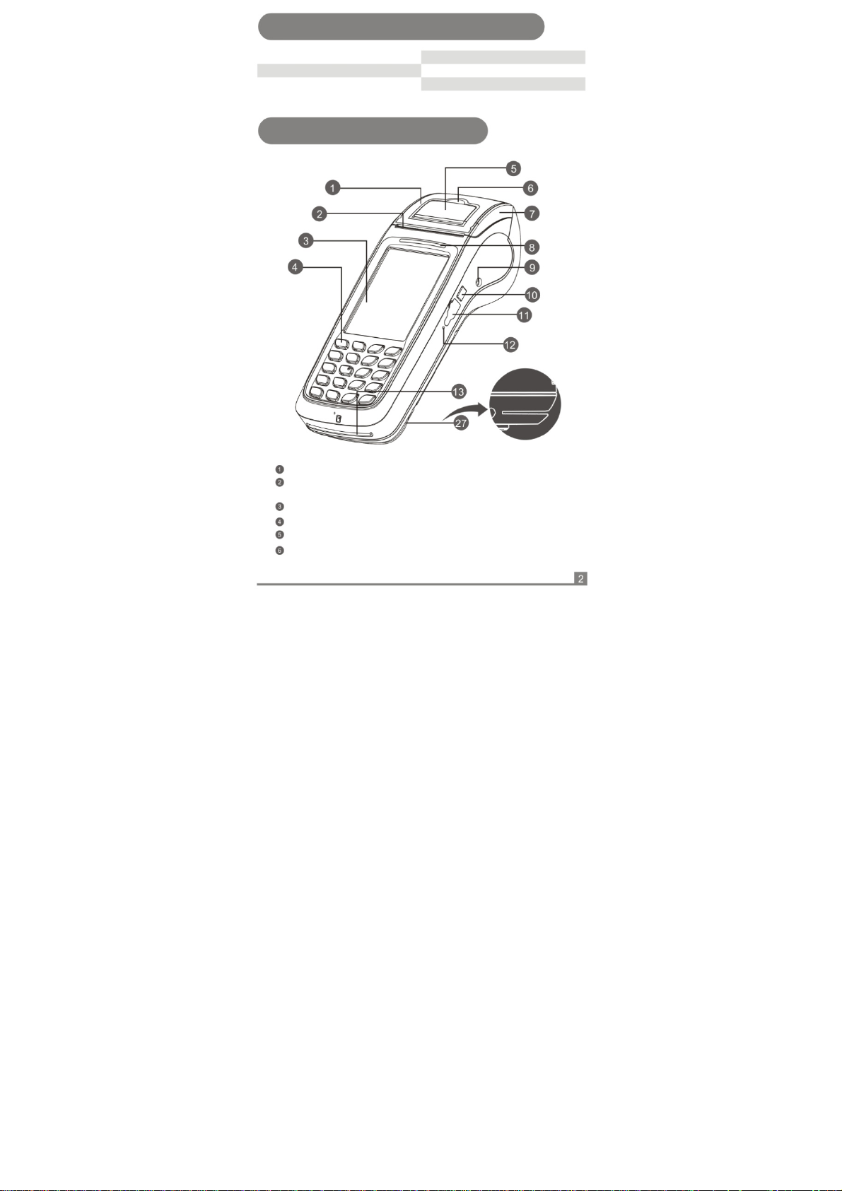
Page 4
Description:
Printer Cover The cover is with a pressing shaft. Open it for loading paper, cover
Indicating Lamp Power and working status indication;
Power Socket Power unit (standard:Φ3.5mm DC jack);
Function Key
S erial Port
Reset Switch Reset;
IC Card Slot IC card front side(with IC)facing up as inser ting;
Speaker Audio remind
Rubber Pad: Slippery and shock protection
SAM&SIM Slot
Stylus Pen Input by handwriting;
Barcode Scanner Barcode scanner for 1D or 2D;
it until locked after loading printer paper ;
Definable;
RS 232 port;
2 SAM card and 1 SIM card under the battery
cover
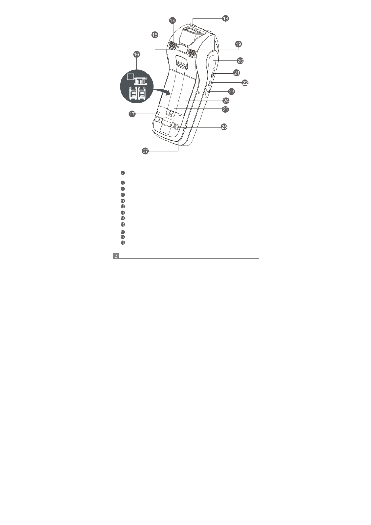
Page 5

Camera & Flash Image recognition & Exposure
Fingerprint Sensor Fingerprint reader (optional);
Phone Jack
Function Key Definable;
Micro USB
Battery Cover The posit ion of the battery to lock;
Wrist Band Convenient operation and bring;
Rubber Pad:
Magcard Reader:
3.5mm standard interface;
USB2.0(OTG);
Slippery and shock protection
The magnetic stripe at the bottom and facing the device
support bi-direction card swiping;
NO.4
Power On
1、Insert the attached power adapter's connector to the MF-2351, linked the AC
cord between the adapter and AC power supply socket;
2、Press the power key( )until LCD display booting information, system will
setup after initialization.
Swiping Card
1、Slide the magnetic card at stable speed, with the magnetic strip upward. 2、
Bi-directional card swiping is supported;
Instructions And Precautions
Page 6

IC Card Read
1、 insert the IC card with the chip upward;
Torn Paper
1、Hand and hold the end of the paper along the cutter from left to right around 45
degrees angle of the direction of the tear, the force should be quickly and evenly.
Installation Of Paper
1、Open the paper bucket lid: Unlock the printer cover( ) by pulling the lever up;
2、Load the thermal paper after open the printer cover. Please notice the paper
come from bottom side;
3、Align the sheet of paper out into the guide slot of the cuter, press the printer
cover back until a "click" sound is heard;
4、To avoid a paper jam or damage the printer, please use standard printing paper
provided by the bank.
Notice
1、Use an outlet with a fuse;
2、Do not damage the power cord and adapter. They can not be used if damaged; 3、
When error occurs, please contact technical support. User's attempting to repair
the device is not covered within warranty;
4、Before connecting the AC power cord to a power supply outlet, you should check
voltage;
5、Do not insert anything into any of the interface of the device, it will seriously
damage the device;
6、Do not place the device in direct sunlight, high temperature, humid or dusty place;
7、Please stay away from liquids
8、Federal Communication Commission Interference Statement
This equipment has been tested and found to comply with the limits for a Class B
digital device, pursuant to Part 15 of the FCC Rules. These limits are designed to
provide reasonable protection against harmful interference in a residential installation.
This equipment generates, uses, and can radiate radio frequency energy and, if not
installed and used in accordance with the instructions, may cause harmful
interference to radio communications. However, there is no guarantee that
interference will not occur in a particular installation.
IC
Page 7

If this equipment does cause harmful interference to radio or t elevision reception,
which can be determined by turning the equipment off and on, the user is encouraged
to try to correct the interference by one or more of the following measures:
• Reorient or relocate the receiving antenna.
• Increase the separation between the equipment and receiver.
• Connect the equipment into an outlet on a circuit different from that to which the
receiver is connected.
• Consult the dealer or an experienced radio/TV technician for help.
FCC Caution:
This device complies with Part 15 of the FCC Rules. Operation is subject to the
following two conditions: (1) This device may not cause harmful interference, and (2)
this device must accept any interference received, including interference that may
cause undesired operation.
Non-modification Statement:
Changes or modifications not expressly approved by the party responsible for
compliance could void the user's authority to operate the equipment.
This device has been tested and meets the FCC RF exposure guidelines. The
maximum SAR value reported is 0.240 w/kg.
Limited Channels fixed for use in the US:
IEEE 802.11b or 802.11g or 802.11n(HT20) operation of this product in the U.S. is
firmware-limited to Channel 1 through 11. IEEE 802.11n(HT40) operation of this
product in the U.S. is firmware-limited to Channel 3 through 9.
Page 8

NO.5 The test program instruction
Caution:
The power supply input for this unit is 9.0V and not 12V or 5V. If you want to
change to another power supply in place of the one in the package, you need
to be cautious and check the output voltage and current.
Content:
1.MSR test
2.ICC test
3.Print test
4.RIF test
5.Wireless,WCDMA test
6.Wifi test
7.Screen test
8.Other functional test
9.Vibration test
10.The one-dimensional bar code test
Double-click the
"MF-2351_appapi_test.exe:
1 .MSR test.
Click the MSR button.
Click on the "MSR Read"
and brush the magnetic
stripe cards in the card
slot. Successfully show:
Page 9

2. ICC test. Click“ICC”.
As the test described abov e, the user can see the other effect.
3. Printer test.
You can see the current version of the NK.
Select the appropriate font size print and note that the paper is placed correctly.
Insert IC card, if you want to test IC command
(ICC Command), click on "IC Check". If IC card
chip does not damage or contact with normal
card slot, you can see the following:
Page 10

4 . RIF test,include A
card,B card and M1
card. click the button.
Each of M1 data is stored in the sector. Each sector has its own key .If appear the
"Authority M1 Card Err", when you use the " M1 Read the Write ", I lustrate the key
Authentication is not passed. It is normal.
5. Wireless, WCDMA test. Click "Auto Dial”, wait for the POS automatically dial. If you
have used WCDMA capabilities, you need to disconnect in order to continue to use
this.
If you want to test M1 function, the first , put M1 on
the RF sensing area, Click on the "M1 Check "to
check card , if non-access module is hardware or the
card is not damaged, you can
see the following:
Page 11

6. Wifi test. Firstly click network
settings on the taskbar.
Click on the "power state" and finally the power is turned on again, then you can
test the other features, click the button again to turn off wifi power.
7. Screen test. Test LCD Module.
The first one is the lock screen, click the button, the screen will lock and screen
automatically unlock after a few seconds. The second is the rot ation of the screen,
click the screen then it will rotate 90 degrees.
Select "Wireless Info”, check the "Notify when
new networks available” , connected to the
network , enter the test program after the
following effect appears:
Page 12

8. Other functional test.
You can see the results after the click of a button.
9 . Vibration test. Vibration testing can test motor is working properly or not.
10. The one-dimensional bar code test.
Put the one-dimensional bar code on the location of about 5 cm from the scanning lamp,
Screen will be prompted to read the one-dimensional bar code as shown above.
Page 13

Tel:+886-2918-8500
:+886-2915-3405
Fax
Partner Tech Corporation
http://www.partner.com.tw
10FL, 233-2, Baoqiao Road, Xindian, New Taipei City, Taiwan
Notice:Product specifications are subject to change without prior notice!
 Loading...