

Page 1
SurfRAID TRITON16S3
User’s Guide
Revision 1.2
Page 2
Copyright
No part of this publication may be reproduced or transmitted in any form
without the prior written consent of Partners Data Systems, Inc.
Trademarks
All products and trade names used in this document are trademarks or
registered trademarks of their respective holders.
Changes
The material in this document is for information only and is subject to change
without notice.
FCC Compliance Statement
This equipment has been tested and found to comply with the limits for a Class B
digital device, pursuant to Part 15 of the FCC rules. These limits are
designed to provide reasonable protection against harmful interference in
residential installations. This equipment generates, uses, and can radiate
radio frequency energy, and if not installed and used in accordance with
the instructions, may cause harmful interference to radio communications.
However, there is not guarantee that interference will not occur in a particular
installation. If this equipment does cause interference to radio or television
equipment reception, which can be determined by turning the equipment off
and on, the user is encouraged to try to correct the interference by one or
more of the following measures:
1. Reorient or relocate the receiving antenna
2. Move the equipment away from the receiver
3. Plug the equipment into an outlet on a circuit different from that to
which the receiver is powered.
4. Consult the dealer or an experienced radio/television technician for
help
All external connections should be made using shielded cables.
Page 3

About This Manual
Welcome to your SurfRAID TRITON16S3 RAID System User’s Guide. This
manual covers everything you need to know in learning how to install or
configure your RAID system. This manual also assumes that you know the basic
concepts of RAID technology. The manual
If have any questions about your RAID system or host integration,
please contact our support group or your account manager.
Partners Data Systems
3663 Via Mercado
San Diego, CA. 91941
800-550-3005
619-415-2000
Chapter 1 Introduction
• Introduces you to Disk Array’s features and general technology concepts.
Chapter 2 Getting Started
• Helps user to identify parts of the Disk Array and prepare the hardware for configuration.
Chapter 3 Configuring
Quick Setup
• Provides a quick setup way to setup your Disk Array.
Customizing Setup
• Provides step-by-step instructions to help you to do setup or re-configure your Disk
Chapter 4 Array Maintenance
Adding Cache Memory
Updating Firmware
Hot Swap Components
Array.
• Provides a detailed procedure to increase cache memory from the default amount of
128MB to higher.
• Provides step-by-step instructions to help you to update the firmware to the latest
version.
• Describes all hot swap modules on Disk Array and provides the detailed procedure to
replace them.
includes the following information.
Page 4

Table of Contents
Chapter 1 Introduction
1.1 Key Features..........................................................................................................
1.2 RAID Concepts.................................................................................................
1.3 SAS Overview..................................................................................................
1.4 Array Definition.................................................................................................
1.4.1 RAID set..................................................................................................
1.4.2 Volume Set...............................................................................................
1.4.3 Easy of Use features..............................................................................
1.4.4 High Availability.......................................................................................
Chapter 2 Getting Started
2.1 Unpacking the subsystem.........................................................................................
2.2 Identifying Parts of the subsystem.....................................................................
2.2.1 Front View......................................................................................................
2.2.2 Rear View.....................................................................................................
2.3 Connecting to SAS Host...................................................................................
2.4 Powering-on the subsystem..............................................................................
2.5 Install Hard Drives...........................................................................................
Chapter 3 Configuring
3.1 Configuring through a Terminal..............................................................................
3.2 Configuring the Subsystem Using the LCD Panel.........................................
3.3 Menu Diagram.......................................................................................................
3.4 Web browser-based Remote RAID management via R-Link Ethernet.......
3.5 Quick Create..........................................................................................................
3.6 Raid Set Functions...............................................................................................
3.6.1 Create Raid Set..........................................................................................
3.6.2 Delete Raid Set............................................................................................
3.6.3 Expand Raid Set...........................................................................................
3.6.4 Offline Raid Set........................................................................................
3.6.5 Activate Incomplete Raid Set...................................................................
3.6.6 Create Hot Spare........................................................................................
3.6.7 Delete Hot Spare.........................................................................................
3.6.8 Rescue Raid Set..........................................................................................
3.7 Volume Set Function..............................................................................................
3.7.1 Create Volume Set......................................................................................
1-2
1-3
1-10
1-11
1-11
1-12
1-12
1-15
2-1
2-3
2-3
2-6
2-9
2-10
2-11
3-1
3-9
3-10
3-15
3-17
3-19
3-19
3-20
3-21
3-23
3-24
3-26
3-27
3-27
3-28
3-28
Page 5

3.7.2 Delete Volume Set......................................................................................
3.7.3 Modify Volume Set........................................................................................
3.7.3.1 Volume Expansion…............................................................................
3.7.4 Volume Set Migration..................................................................................
3.7.5 Check Volume Set........................................................................................
3.7.6 Stop Volume Set Check..............................................................................
3.8 Physical Disk Drive....................................................................................................
3.8.1 Create Pass-Through Disk........................................................................
3.8.2 Modify Pass-Through Disk.........................................................................
3.8.3 Delete Pass-Through Disk........................................................................
3.8.4 Identify Selected Drive.................................................................................
3.9 System Configuration...........................................................................................
3.9.1 System Configuration.................................................................................
3.9.2 Ethernet Config.............................................................................................
3.9.3 Alert by Mail Config....................................................................................
3.9.4 SNMP Configuration.....................................................................................
3.9.5 NTP Configuration........................................................................................
3.9.6 View Events..................................................................................................
3.9.7 Generate Test Events.................................................................................
3.9.8 Clear Events Buffer......................................................................................
3.9.9 Modify Password..........................................................................................
3.9.10 Upgrade Firmware.................................................................................
3.10 Information Menu....................................................................................................
3.10.1 Raid Set Hierarchy.....................................................................................
3.10.2 System Information...............................................................................
3.10.3 Hardware Monitor......................................................................................
3.11 Creating a new RAID or Reconfiguring an Existing RAID…..............................
Chapter 4 Array Maintenance
4.1 Upgrading the Firmware........................................................................................
4.1.1 Upgrading Firmware via RSR232 Serial Terminal...................................
4.1.1 Upgrading Firmware via RJ45 WEB Interface….....................................
4.2 Hot Swap components........................................................................................
4.3.1 Replacing a disk.........................................................................................
4.3.2 Replacing a Power Supply........................................................................
Appendix A Technical Specification...................................................
4.3.3 Replacing a Fan..........................................................................................
3-31
3-32
3-32
3-34
3-35
3-36
3-37
3-37
3-38
3-39
3-39
3-40
3-40
3-43
3-44
3-45
3-46
3-47
3-48
3-49
3-49
3-50
3-51
3-51
3-51
3-52
3-53
4-1
4-2
4-6
4-8
4-8
4-9
4-10
A-1
Page 6

Chapter 1
Introduction
The SurfRAID16S3 RAID subsystem is a SAS-to-Serial ATA II RAID (Redundant
Arrays of Independent Disks) disk array subsystem. It consists of a RAID disk
array controller and sixteen (16) disk trays.
The subsystem is a “Host Independent” RAID subsystem supporting RAID levels
0, 1, 3, 5, 6, 0+1 and JBOD. Regardless of the RAID level the subsystem is
configured for, each RAID array consists of a set of disks which to the user
appears to be a single large disk capacity.
One unique feature of these RAID levels is that data is spread across separate
disks as a result of the redundant manner in which data is stored in a RAID
array. If a disk in the RAID array fails, the subsystem continues to function
without any risk of data loss. This is because redundant information is stored
separately from the data. This redundant information will then be used to reconstruct any data that was stored on a failed disk. In other words, the subsystem can tolerate the failure of a drive without losing data while operating
independently of each other.
The subsystem is also equipped with an environment controller which is
capable of accurately monitoring the internal environment of the subsystem such
as; power supplies, fans, temperatures and voltages. The disk trays allow
you to install any type of 3.5-inch hard drive. Its modular design allows hotswapping of hard drives, fans and power supplies without interrupting the
subsystem’s operation.
Page 7

1.1 Key Features
Subsystem Features:
• Features an Intel 80321 64 bit RISC I/O processor
• Build-in 256MB cache memory, expandable up to 1024MB
• Two SAS (3Gb/s) host ports
• Smart-function LCD panel
• Supports up to sixteen (16) 1" hot-swappable Serial ATA II hard drives
• Redundant load sharing hot-swappable power supplies
• High quality advanced cooling fans
• Local audible event notification alarm
• Supports password protection and UPS connection
• Built-in R-Link LAN port interface for remote management & event notification
• Dual host channels support clustering technology
• Real time drive activity and status indicators
• RAID Function Features:
• Supports RAID levels 0, 1, 0+1, 3, 5, 6 and JBOD
• Supports hot spare and automatic hot rebuild
• Allows online capacity expansion within the enclosure
• Support spin down drives when not in use to extend service (MAID)
• Transparent data protection for all popular operating systems
• Bad block auto-remapping
• Supports multiple array enclosures per host connection
• Multiple RAID selection
• Array roaming
•
Online RAID level migration
Page 8

1.2 RAID Concepts
RAID Fundamentals
The basic idea of RAID (Redundant Array of Independent Disks) is to combine
multiple inexpensive disk drives into an array of disk drives to obtain performance,
capacity and reliability that exceeds that of a single large drive. The array of
drives appears to the host computer as a single logical drive.
Six types of array architectures, RAID 1 through RAID 6, were originally defined;
each provides disk fault-tolerance with different compromises in features and
performance. In addition to these five redundant array architectures, it has become
popular to refer to a non-redundant array of disk drives as a RAID 0 array.
Disk Striping
Fundamental to RAID technology is striping. This is a method of combining
multiple drives into one logical storage unit. Striping partitions the storage
space of each drive into stripes, which can be as small as one sector (512
bytes) or as large as several megabytes. These stripes are then interleaved in
a rotating sequence, so that the combined space is composed alternately of
stripes from each drive. The specific type of operating environment determines
whether large or small stripes should be used.
Most operating systems today support concurrent disk I/O operations across
multiple drives. However, in order to maximize throughput for the disk subsystem,
the I/O load must be balanced across all the drives so that each drive can be kept
busy as much as possible. In a multiple drive system without striping, the disk I/O
load is never perfectly balanced. Some drives will contain data files that are
frequently accessed and some drives will rarely be accessed.
Page 9
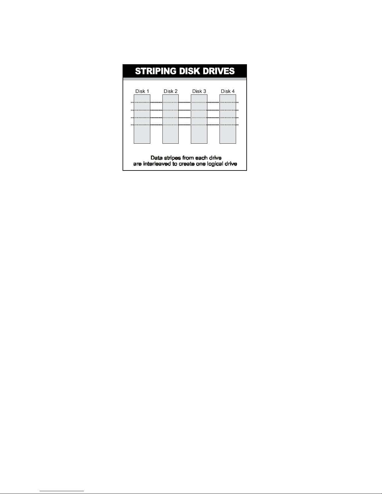
By striping the drives in the array with stripes large enough so that each record
falls entirely within one stripe, most records can be evenly distributed across all
drives. This keeps all drives in the array busy during heavy load situations. This
situation allows all drives to work concurrently on different I/O operations, and
thus maximize the number of simultaneous I/O operations that can be performed
by the array.
Definition of RAID Levels
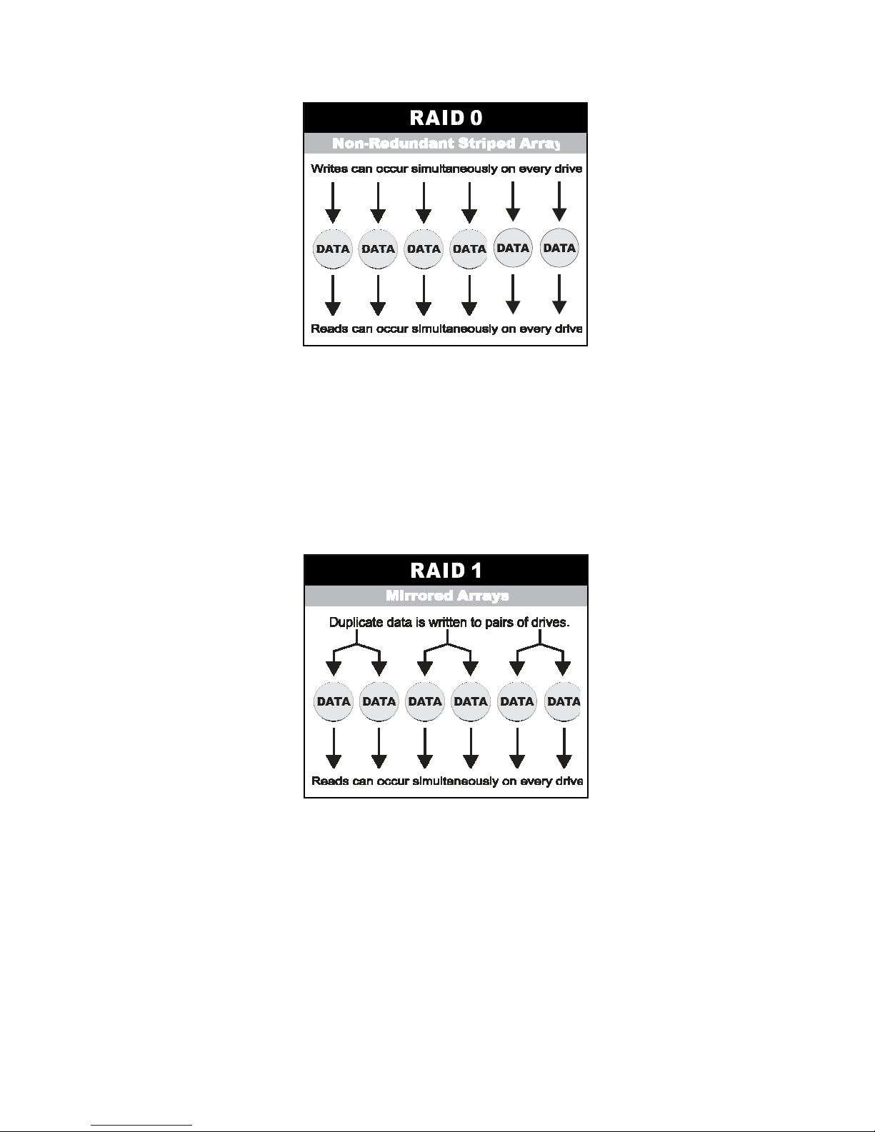
RAID 0
redundancy. RAID 0 arrays can be configured with large stripes for multi-user
environments or small stripes for single-user systems that access long sequential
records. RAID 0 arrays deliver the best data storage efficiency and performance
of any array type. The disadvantage is that is if one drive in a RAID 0 array fails,
the entire array fails.
is typically defined as a group of striped disk drives without parity or data
Page 10
RAID 1
duplicate data, but appear to the computer as a single drive. Although striping is
not used within a single mirrored drive pair, multiple RAID 1 arrays can be striped
together to create a single large array consisting of pairs of mirrored drives. All
writes must go to both drives of a mirrored pair so that the information on the
drives is kept identical. However, each individual drive can perform simultaneous,
independent read operations. Mirroring thus doubles the read performance of a
single non-mirrored drive and while the write performance is unchanged. RAID 1
delivers the best performance of any redundant array type. In addition, there is
less performance degradation during drive failure than in RAID 5 arrays.
, also known as disk mirroring, is simply a pair of disk drives that store
Page 11
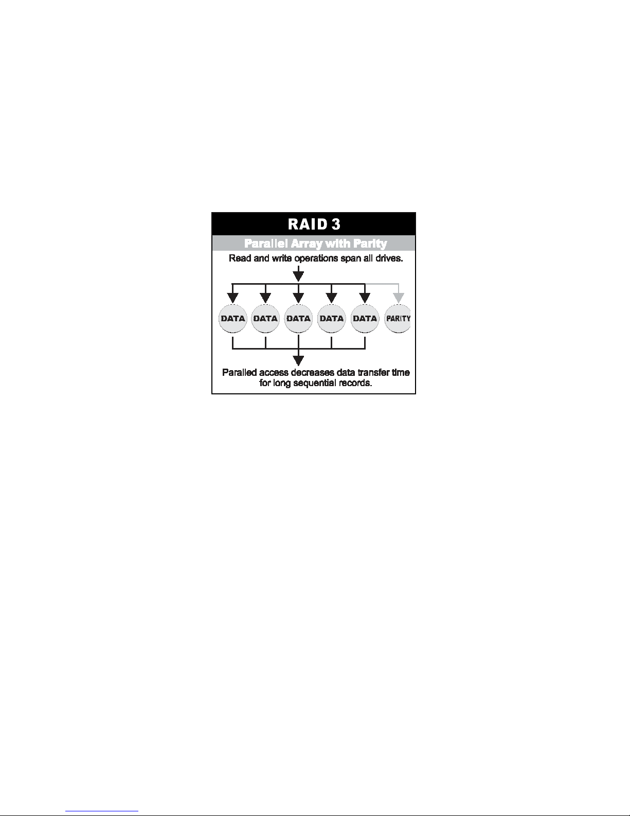
RAID 3
sector-stripes data across groups of drives, but one drive in the group is
dedicated to storing the parity information. RAID 3 relies on the embedded ECC
in each sector for error detection. In the case of drive failure, data recovery is
accomplished by calculating the exclusive OR (XOR) of the information recorded
on the remaining drives. Records typically span all drives, which optimizes the
disk transfer rate. Because each I/O request accesses every drive in the array,
RAID 3 arrays can satisfy only one I/O request at a time. RAID 3 delivers the best
performance for single-user, single-tasking environments with long records.
Synchronized-spindle drives are required for RAID 3 arrays in order to avoid
performance degradation with short records. RAID 5 arrays with small stripes can
yield similar performance to RAID 3 arrays.
Under
no dedicated parity drive, all drives contain data and read operations can be
overlapped on every drive in the array. Write operations will typically access one
data drive and one parity drive. However, because different records store their
parity on different drives, write operations can usually be overlapped.
RAID 5
parity information is distributed across all the drives. Since there is
Page 12
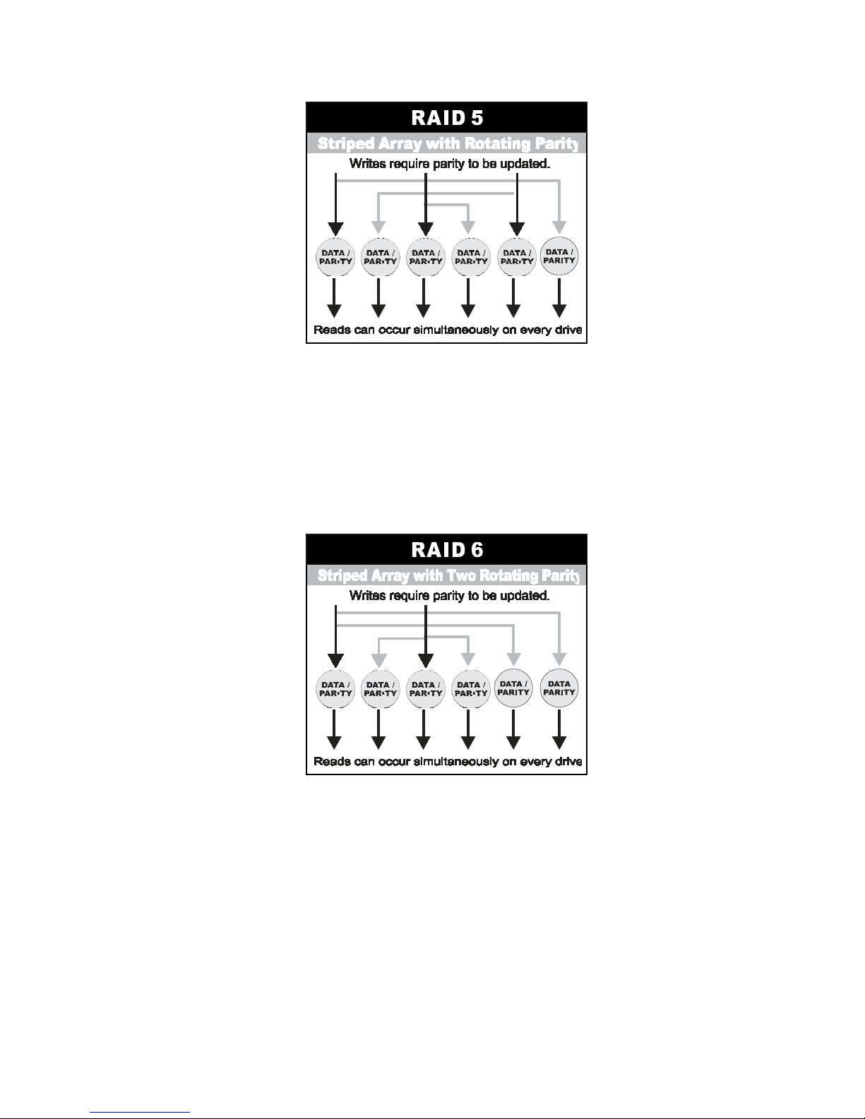
RAID 6
is similar to RAID 5 in that data protection is achieved by writing parity
information to the physical drives in the array. With RAID 6, however, two sets of
parity data are used. These two sets are different, and each set occupies a capacity
equivalent to that of one of the constituent drives. The main advantage of RAID 6
High data availability – any two drives can fail without loss of critical data.
is
Page 13

Dual-level RAID
achieves a balance between the increased data availability
inherent in RAID 1 and RAID 5 and the increased read performance inherent in
disk striping (RAID 0). These arrays are sometimes referred to as
RAID 10 and RAID 0+5 or RAID 50.
In summary:
RAID 0+1
• RAID 0 is the fastest and most efficient array type but offers no faulttolerance. RAID 0 requires a minimum of two drives.
• RAID 1 is the best choice for performance-critical, fault-tolerant
environments. RAID 1 is the only choice for fault-tolerance if no more than
two drives are used.
• RAID 3 can be used to speed up data transfer and provide fault-tolerance in
single-user environments that access long sequential records. However,
RAID 3 does not allow overlapping of multiple I/O operations and requires
synchronized-spindle drives to avoid performance degradation with short
records. RAID 5 with a small stripe size offers similar performance.
• RAID 5 combines efficient, fault-tolerant data storage with good performance
characteristics. However, write performance and performance during
drive failure is slower than with RAID 1. Rebuild operations also require
more time than with RAID 1 because parity information is also
reconstructed. At least three drives are required for RAID 5 arrays.
• RAID 6 is essentially an extension of RAID level 5 which allows for
additional fault tolerance by using a second independent distributed
parity scheme (two-dimensional parity). Data is striped on a block level
across a set of drives, just like in RAID 5, and a second set of parity
is calculated and written across all the drives; RAID 6 provides for an
extremely high data fault tolerance and can sustain multiple
simultaneous drive failures. The perfect solution for mission critical
applications.
or
Page 14
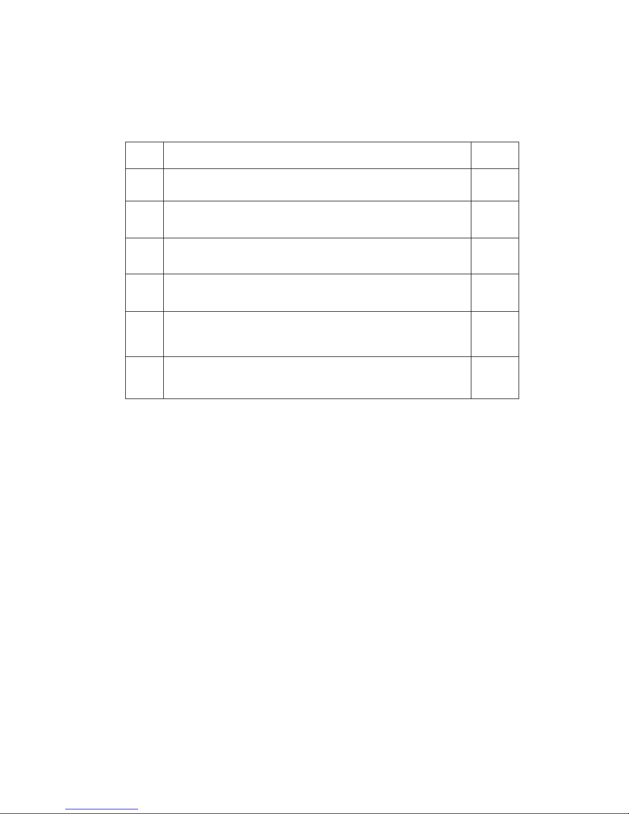
RAID Management
The subsystem can implement several different levels of RAID technology.
RAID levels supported by the subsystem are shown below.
RAID
Level
0 + 1
0
Block striping is provide, which yields higher performance than with
individual drives. There is no redundancy.
1
Drives are paired and mirrored. All data is 100% duplicated on an
equivalent drive. Fully redundant.
3
Data is striped across several physical drives. Parity protection is used
for data redundancy.
5
Data is striped across several physical drives. Parity protection is used
for data redundancy.
6
Data is striped across several physical drives. Parity protection is used
for data redundancy. Requires N+2 drives to implement because of
two-dimensional parity scheme
Combination of RAID levels 0 and 1. This level provides striping and
redundancy through mirroring.
Description
Min
Drives
1
2
3
3
4
4
Page 15

1.3 Serial-Attached SCSI (SAS) Overview
What is SAS? Serial-Attached SCSI (SAS) is the newest storage interface for
Direct-Attached Storage (DAS). SAS is the successor to the highly successful
parallel Ultra 320 SCSI interface. SAS improves and expands upon the parallel
SCSI technology, and is supported by the ANSI T10 Standards Committee.
Why SAS? Answer; Performance, connectivity and scalability.
One of the major differences between parallel SCSI and SAS is that SAS uses a
serial bus as opposed to a parallel bus. Ultra 320 parallel SCSI has reached the
limit of parallel SCSI performance, and anything beyond Ultra 320 is not
feasible due to the fact that parallel SCSI clock rates are limited
by bit- skewing. This is where SAS comes in. SAS transmission is done
serially, and results in a myriad of advantages over parallel SCSI.
Performance
• The serial nature of SAS results in a huge increase in performance over
parallel SCSI.
• No bit-skewing and is self-clocking.
• Transfer rates up to 3.0 Gb/s per link.
• Full duplex which results in a total of 6.0 Gb/s per link.
• Link aggregation into 4x wide ports for a total of 24.0 Gb/s.
•
Extensive command queue.
Connectivity/Scalability
A new concept introduced by SAS is the expander. Expanders act like
miniature switches for routing data from the SAS controller chip to the hard
disks. The connectivity / scalability benefits of SAS are:
• Dedicated point-to-point connection between initiator and target.
• SAS expanders make scalability up to 16K devices in a single SAS
domain possible.
• Each device is uniquely identified with a World Wide Name (WWN), so
there is no longer a need for SCSI IDs.
•
Using SCSI Tunneling Protocols (STP), SAS is compatible with SATA II
HDDs.
Page 16

Availability
In this fast-paced society, data needs to be available to clients whenever they
need it. SAS was designed with availability in mind. SAS include the following
benefits:
• Dual ports for redundant controller functionality
• Support for multiple initiators
• Hot swappable for easy removal / replacement of the SAS drive
1.4 Array Definition
1.4.1 RAID Set
A RAID Set is a group of disks containing one or more volume sets. It has the
following features in the RAID subsystem controller:
1. Up to 128 RAID Sets are supported per RAID subsystem controller.
2. It is impossible to have multiple RAID Sets on the same disks.
A Volume Set must be created either on an existing RAID set or on a group of
available individual disks (disks that are not yet a part of a raid set). If there
are pre-existing raid sets with available capacity and enough disks for
specified RAID level desired, then the volume set will be created in the
existing raid set of the user’s choice. If physical disks of different capacity
are grouped together in a raid set, then the capacity of the smallest disk will
become the effective capacity of all the disks in the raid set.
Page 17
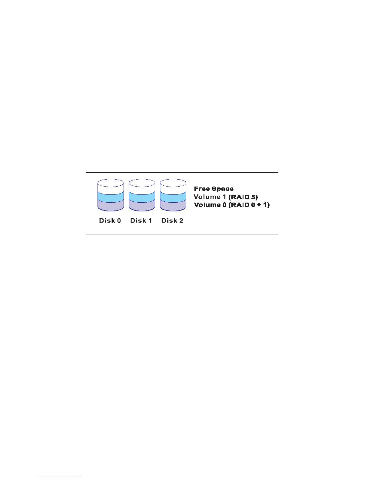
1.4.2 Volume Set
A Volume Set is seen by the host system as a single logical device. It is
organized in a RAID level with one or more physical disks. RAID level refers
to the level of data performance and protection of a Volume Set. A Volume
Set capacity can consume all or a portion of the disk capacity available in a
RAID Set. Multiple Volume Sets can exist on a group of disks in a RAID Set.
Additional Volume Sets created in a specified RAID Set will reside on all the
physical disks in the RAID Set. Thus each Volume Set on the RAID Set will
have its data spread evenly across all the disks in the RAID Set. Volume Sets
of different RAID levels may coexist on the same RAID Set.
In the illustration below, Volume 1 can be assigned a RAID 5 level of operation
while Volume 0 might be assigned a RAID 0+1 level of operation.
1.4.3 Easy of Use features
1.4.3.1 Instant Availability/Background Initialization
RAID 0 and RAID 1 volume set can be used immediately after the creation. But
the RAID 3, 5 and 6 volume sets must be initialized to generate the parity. In
the Normal Initialization, the initialization proceeds as a background task, the
volume set is fully accessible for system reads and writes. The operating system can instantly access to the newly created arrays without requiring a reboot
and waiting the initialization complete. Furthermore, the RAID volume set is
also protected against a single disk failure while initialing. In Fast Initialization,
the initialization proceeds must be completed before the volume set ready for
system accesses.
Page 18
1.4.3.2 Array Roaming
The RAID subsystem stores configuration information both in NVRAM and on
the disk drives It can protect the configuration settings in the case of a disk
drive or controller failure. Array roaming allows the administrators the ability to
move a completely raid set to another system without losing the RAID
configuration and data on that raid set. If a server fails to work, the raid set
disk drives can be moved to another server and inserted in any order.
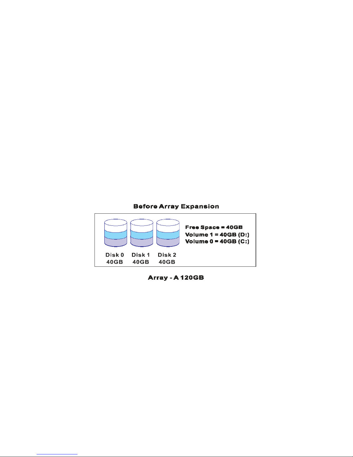
1.4.3.3 Online Capacity Expansion
Online Capacity Expansion makes it possible to add one or more physical
drive to a volume set, while the server is in operation, eliminating the need to
store and restore after reconfiguring the raid set. When disks are added to a
raid set, unused capacity is added to the end of the raid set. Data on the
existing volume sets residing on that raid set is redistributed evenly across all
the disks. A contiguous block of unused capacity is made available on the raid
set. The unused capacity can create additional volume set. The expansion
process is illustrated as following figure.
Page 19
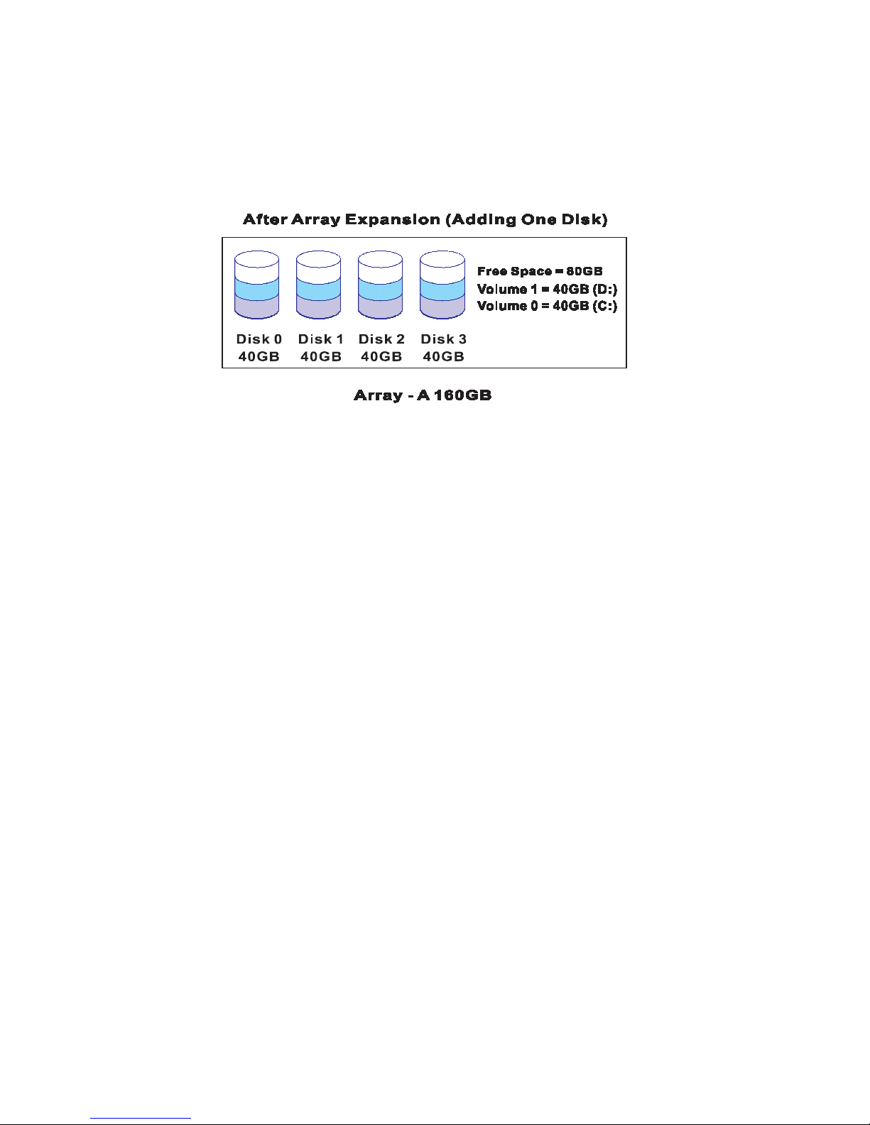
The RAID subsystem controller redistributes the original volume set over the
original and newly added disks, using the same fault-tolerance configuration.
The unused capacity on the expand raid set can then be used to create an
additional volume sets, with a different fault tolerance setting if user need to
change.
1.4.3.4 Online RAID Level and Stripe Size Migration
User can change both the RAID level and stripe size of an existing volume set,
while the server is online and the volume set is in use. Online RAID level/stripe
size migration can prove helpful during performance tuning activities as well as
in the event that additional physical disks are added to the RAID subsystem.
For example, in a system using two drives in RAID level 1, you could add
capacity and retain fault tolerance by adding one drive. With the addition of
third disk, you have the option of adding this disk to your existing RAID logical
drive and migrating from RAID level 1 to 5. The result would be parity fault
tolerance and double the available capacity without taking the system off.
Page 20

1.4.4 High availability
1.4.4.1 Creating Hot Spares
A hot spare drive is an unused online available drive, which is ready for
re- placing the failure disk drive. In a RAID level 1, 0+1, 3, 5 or 6 raid set,
any unused online available drive installed but not belonging to a raid set
can define as a hot spare drive. Hot spares permit you to replace failed
drives without powering down the system. When RAID subsystem detects a
UDMA drive failure, the system will automatic and transparent rebuilds
using hot spare drives. The raid set will be reconfigured and rebuilt in the
background, while the RAID subsystem continues to handle system request.
During the automatic rebuild process, system activity will continue as normal,
however, the system performance and fault tolerance will be affected.
Important:
The hot spare must have at least the same or more capacity as the
drive it is replacing.
1.4.4.2 Hot-Swap Disk Drive Support
The RAID subsystem has built the protection circuit to support the replacement
of UDMA hard disk drives without having to shut down or reboot the system.
The removable hard drive tray can deliver “hot swappable,” fault-tolerant RAID
solutions at prices much less than the cost of conventional SCSI hard disk
RAID subsystems. We provide this feature for subsystems to provide the
advanced fault tolerant RAID protection and “online” drive replacement.
Page 21

1.4.4.3 Hot-Swap Disk Rebuild
A Hot-Swap function can be used to rebuild disk drives in arrays with data
redundancy such as RAID level 0, 1, 0+1, 3, 5 and 6. If a hot spare is not
available, the failed disk drive must be replaced with a new disk drive so that
the data on the failed drive can be rebuilt. If a hot spare is available, the
rebuild starts automatically when a drive fails. The RAID subsystem
automatically and transparently rebuilds failed drives in the background with user
definable rebuild rates. The RAID subsystem will automatically restart the
system and the rebuild if the system is shut down or powered off abnormally
during a reconstruction procedure condition. When a disk is Hot Swap,
although the system is functionally operational, the system may no longer be
fault tolerant. Fault tolerance will be lost until the removed drive is replaced
and the rebuild operation is completed.
Page 22

Chapter 2
Getting Started
Getting started with the subsystem consists of the following
sections:
• Unpack the storage subsystem.
• Identifying Parts of the subsystem.
• Connect the SAS Cables.
• Power on the subsystem.
• Install Hard Drives.
2.1 Unpacking the Subsystem
Before continuing, first unpack the subsystem and verify that the contents of
the shipping carton are all there and in good condition. Before removing the
subsystem from the shipping carton, visually inspect the physical condition of
the shipping carton. Exterior damage to the shipping carton may indicate that
the contents of the carton are damaged. If any damage is found, do not
remove the components; contact Partners Data System for further
instructions by calling 800-550-3005, option 2 for support or contacting
your account manager.
Page 23
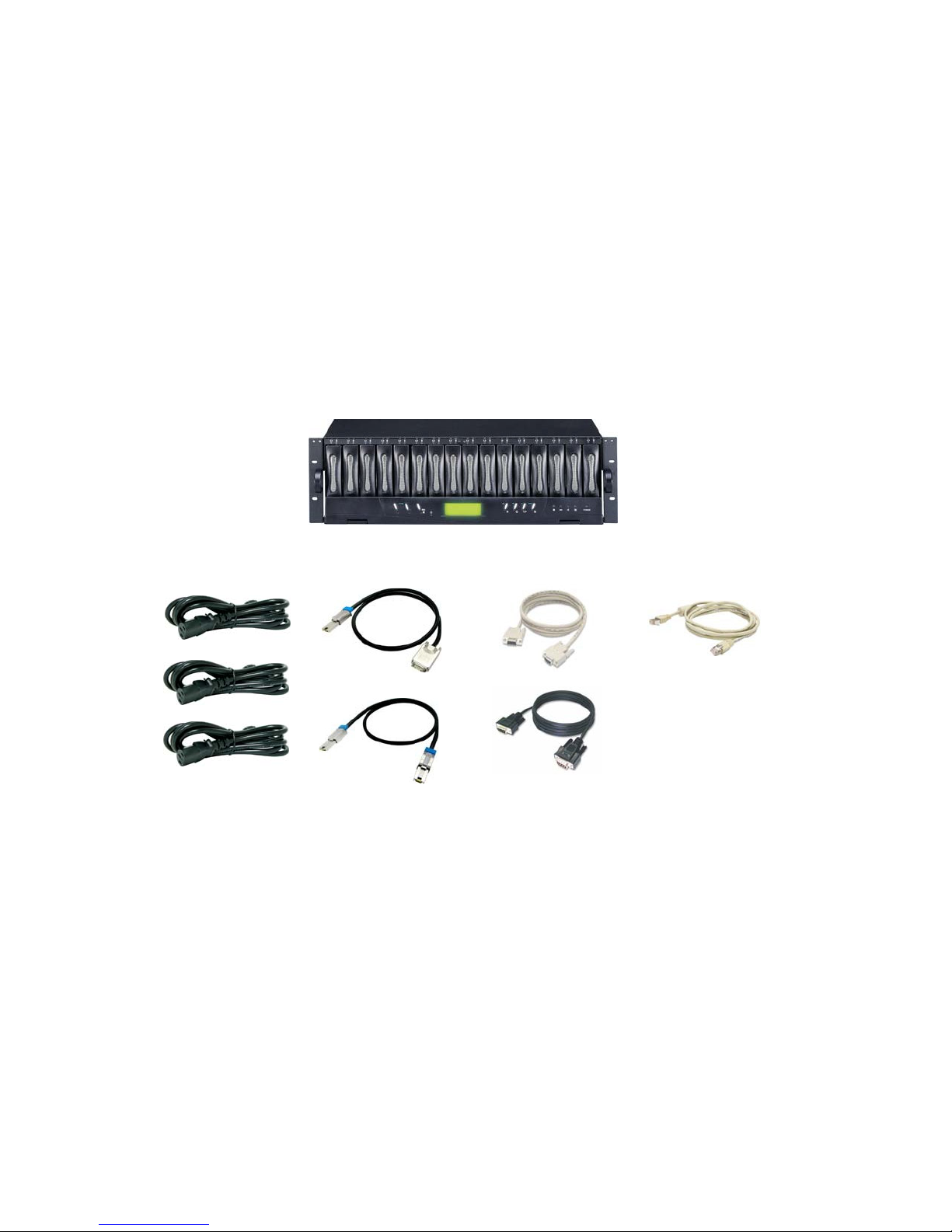
The package contains the following items:
• SR-TRITON16S3 RAID subsystem unit
• Three power cords
• Two external SAS cables (Optional)
• One external null modem cable
• One external UPS cable
• One RJ-45 Ethernet cable
• Installation Reference Guide
• 19” Rack mount kit.
If any of these items are missing or damaged, please contact Partners Data
Systems for assistance.
Page 24
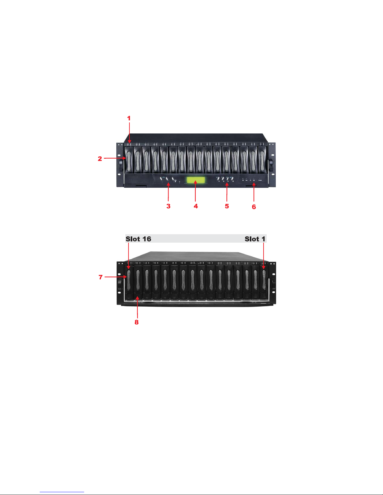
2.2 Identifying Parts of the subsystem
The illustrations below identify the various features of the subsystem. Get
yourself familiar with these terms as it will help you when you read further in
the following sections.
2.2.1 Front View
Page 25
1. HDD status Indicator
Parts
HDD Status LEDs
HDD access LEDs
Access LED Status LED
Function
Green LED indicates power is on and hard drive status
is good for this slot. If there is no hard drive, the LED is red. If
hard drive de fect ed in this slo t or the hard drive is failure, the
LED is orange.
These LED will blink blue when the hard drive is being accessed.
2. HDD trays 1 ~ 16 (From right to left)
3. Smart Function Panel - Function Keys
Activity LED
Parts
Blue blinking LED indicates controller is activity.
Function
4. LCD display panel
5. Smart Function Panel - Function Keys for RAID configuration
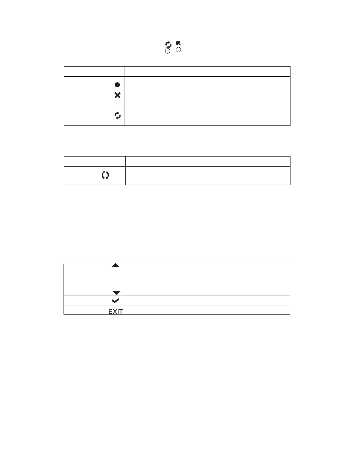
The smart LCD panel is where you will configure the RAID subsystem. If you
are configuring the subsystem using the LCD panel, please press the controller
button to configure your RAID subsystem.
Parts
Up and Down
arrow buttons
Use the Up or Down arrow keys to go through the
information on the LCD screen. This is also used to move
between each menu when you configure the subsystem.
Function
Select button
Exit button
This is used to enter the option you have selected.
Press this button to return to the previous menu.
Page 26
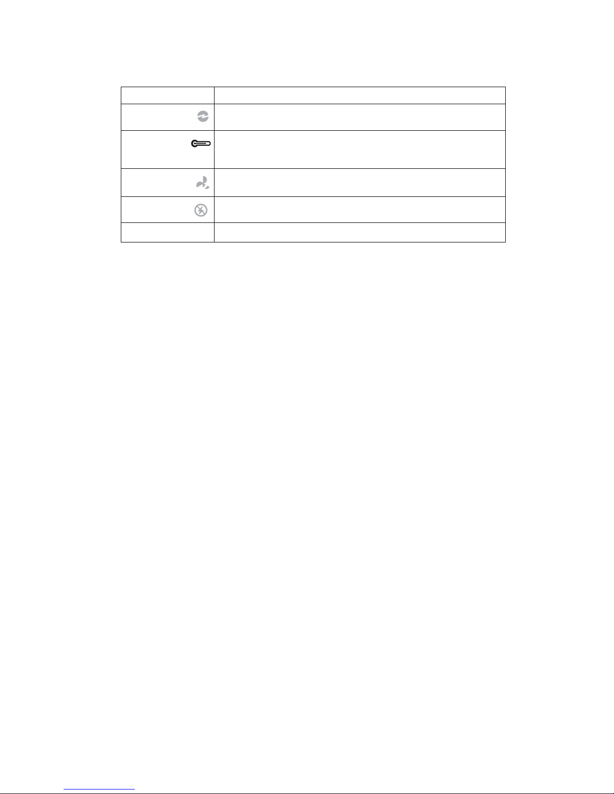
6. Environment status
Parts
Voltage warning
LED
Over temp LED
Fan fail LED
Power fail LED
Power LED
An alarm will sound warning of a voltage abnormality
and this LED will turn red.
If temperature irregularity in these systems occurs (HDD slot
temperature o ver 55
alarm will sound.
When a fan’s rotation speed is lower than 1500rpm, this LED will turn
red and an alarm will sound.
If a redundant power supply fails, this LED will turn red and an alarm
will sound.
Green LED indicates power is on.
7. Tray Lever
8. Tray Latch
Function
o
C), this LED wi ll turn red and an
Page 27
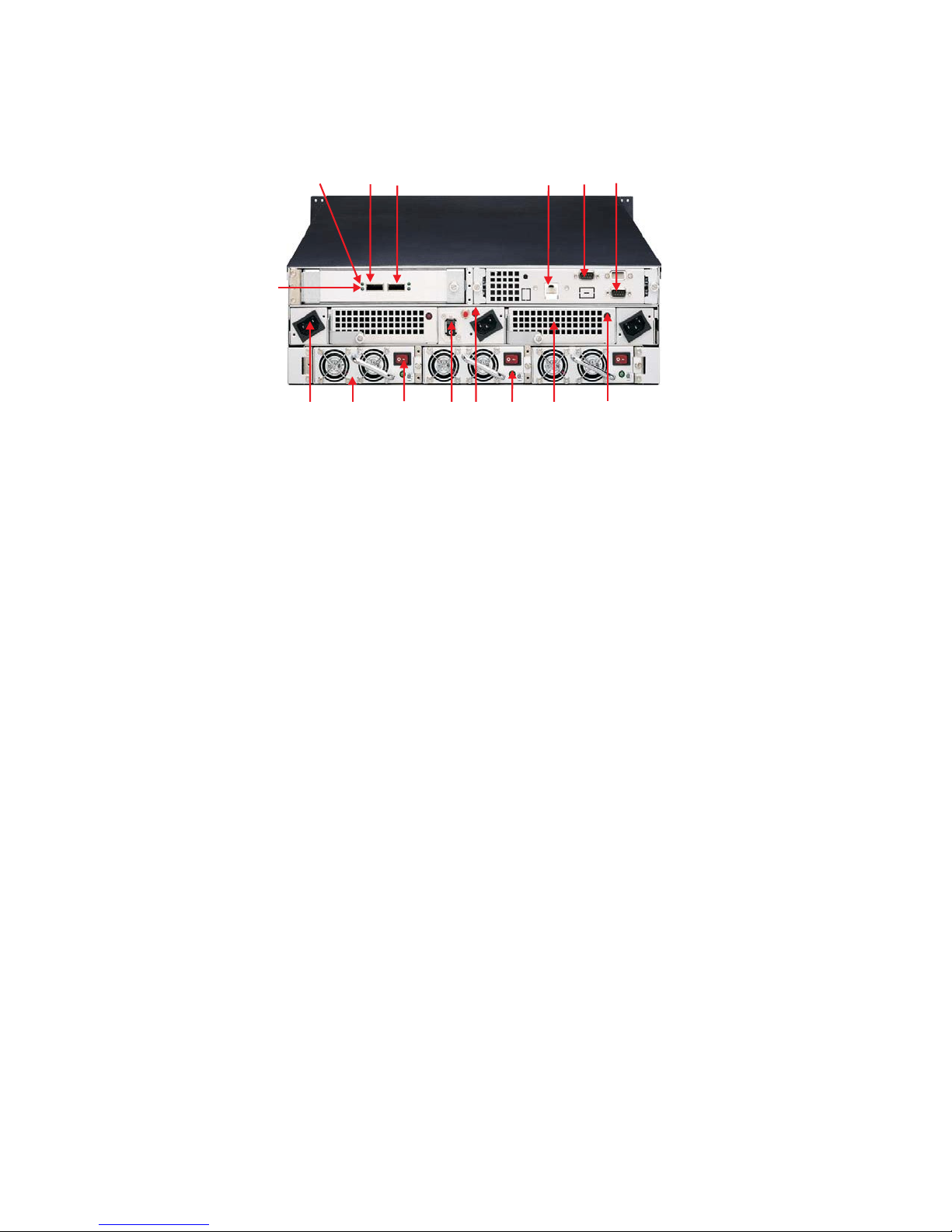
2.2.2 Rear View
1. Host “A” Activity LED
When there is activity on the Host Channel, the LED is Blue.
2. Host Channel A
The subsystem is equipped with 2 host channels (Host channel A and
Host channel B). Each host channel with one SAS connector at the rear
of the subsystem for connecting to a SAS Hub/Switch or Server’s SAS
interface.
3. Host Channel B
Connect to Host’s SAS adapter.
4. R-Link Port: RJ-45 Ethernet for remote management
The subsystem is equipped with one 10/100 Ethernet RJ45 LAN port. You use
web-based browser to management RAID subsystem through Ethernet for remote configuration and monitoring.
Page 28

• Link LED: Green LED indicates Ethernet is linking.
• Access LED: The LED will blink orange when the 100Mbps Ethernet is
being accessed.
5. Uninterrupted Power Supply (UPS) Port
The subsystem may come with an optional UPS port allowing you to connect a
UPS device. Connect the cable from the UPS device to the UPS port located at
the rear of the subsystem. This will automatically allow the subsystem to use
the functions and features of the UPS.
6. Monitor Port
The subsystem is equipped with a serial monitor port allowing you to connect a
PC or terminal.
7. Host “A” Link LED
Green LED indicates Host channel is connected.
8. AC power input socket 1 ~ 3 (From left to right)
9. Power Supply Unit 1 ~ 3 (From left to right)
Three power supplies (power supply 1, power supply 2 and power supply 3)
are located at the rear of the subsystem. Turn on the power of these power
supplies to power-on the subsystem. The “power” LED at the front panel will
turn green.
If a power supply fails to function or a power supply was not turned on, the
“ ” Power fail LED will turn red and an alarm will sound. An error message
will also appear on the LCD screen warning of power failure.
10. Power Supply Unit on / off switch
11. System power on / off switch
Page 29

12. Power Supply Fail indicator
If a power supply fails, this LED will turn red.
13. Power Supply Power On Indicator
Green LED indicates power is on.
14. Cooling Fan module 1 ~ 2 (From left to right)
Two blower fans are located at the rear of the subsystem. They provide
sufficient airflow and heat dispersion inside the chassis. In case a fan fails to
function, the “ ” Fan fail LED will turn red and an alarm will sound. You
will also see an error message appear in the LCD screen warning
you of fan failure.
15. Fan Fail indicator
If a fan fails, this LED will turn red.
Page 30
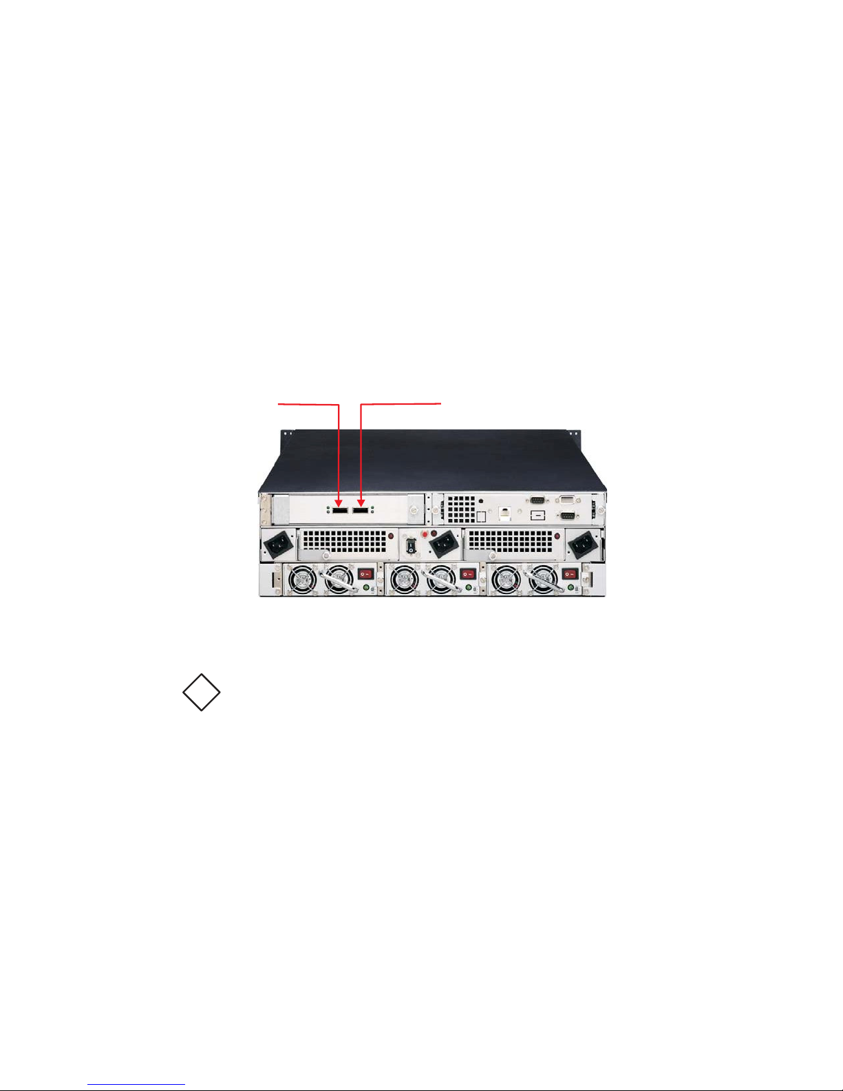
2.3 Connecting to SAS HBA
The subsystem supports SAS interface which provides fast 300MB data
transfer rate. This section describes the location of the host channels and
instructions on connecting external SAS devices.
1. Configure the SAS port Mapping.
2. The package comes with two SAS cables. Attach one end of he SAS
cable to one of the SAS connectors and the other end to
the host adapter’s external SAS connector or to the SAS Hub/Switch.
(The host adapter is installed in your Host subsystem.)
3. Connect the other host system using the other SAS cable if you w ant to
configure subsystem into multi-host attachment.
Note:
!
For safety reasons, make sure the Disk Array and Host Computer
turned off when you plug-in the SAS cable.
are
Page 31
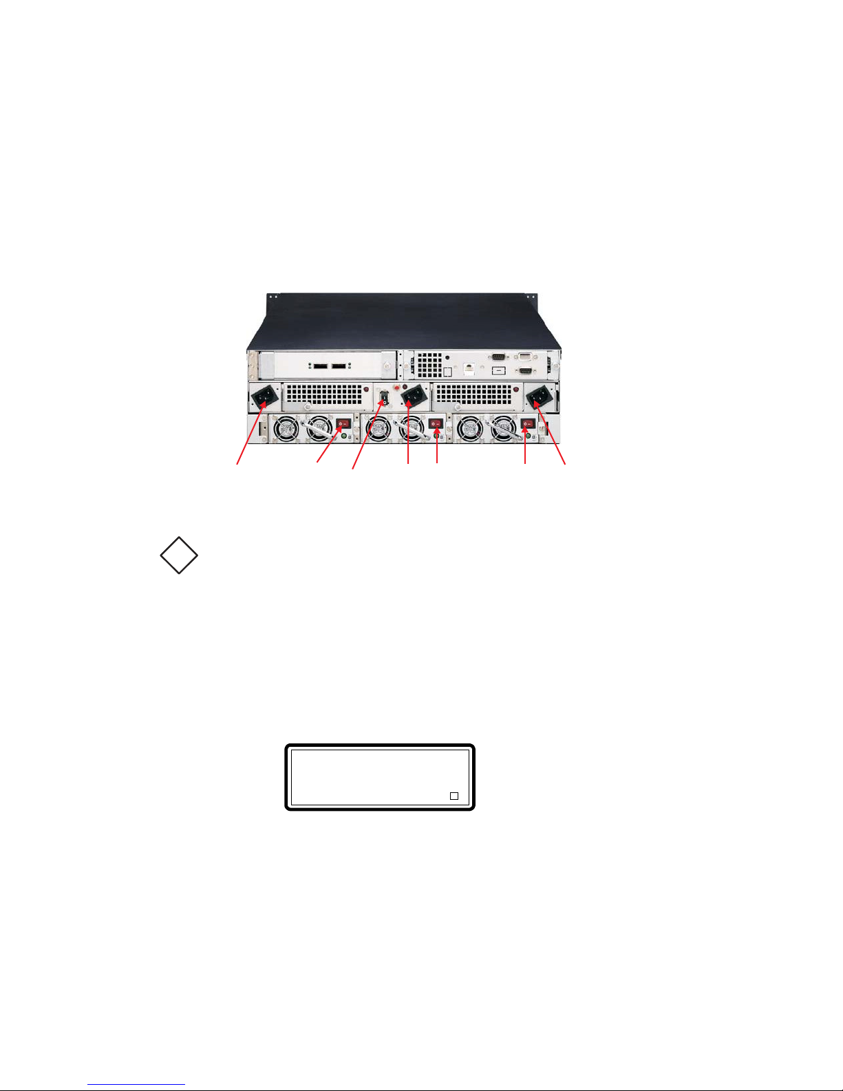
2.4 Powering-on the Subsystem
When you connect the Disk Array to the Host computer, you should press the
ON/OFF Power Supply Switch on both of the power supply units and the Main
Switch. It will turn the Disk Array on and the Self-Test will be
started automatically.
1. Plug in all the power cords or power connectors located at the rear of
the subsystem.
Note:
The subsystem is equipped with N+1 redundant PFC (power factor
!
correction), full range power supplies. The subsystem will
automatically select correct input voltage.
2. Turn on the power. Before turning the system power switch on, make
sure all the power switches of power units 1 ~ 3 are on.
3. The “Power” LED on the front panel will turn green. After a few moments
the LCD should display the following message:
SR-TRITON16S3
Assigned IP Address
Page 32
2.5 Install Hard Drives
The subsystem supports hot-swapping allowing you to install or replace a hard
drive while the subsystem is running.
Note: If new installation of RAID system, install RAID system into data
center rack before installing disk drives. Power on the RAID system, only
after all the disk drives have been inserted into RAID system chassis. If a
preconfigured raid system all disks for that system need to be installed. Only
the cold shelf spare should be left out of the raid system.
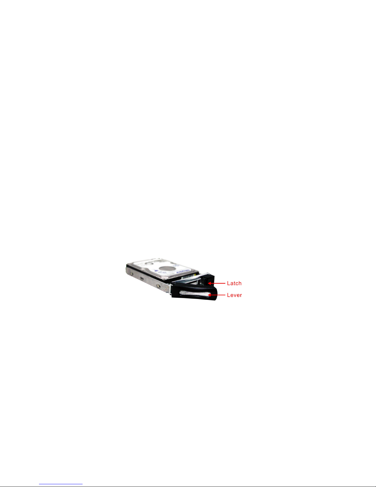
1. Slide the tray into a RAID system disk drive slot until it clicks into place.
Press the lever in until you hear the latch click into place.
2. If the RAID system is already powered on the HDD status LED will turn
green on front panel above the disk drive.
3. If the HDD power LED did not turn green, check the hard drive is in good
condition. If the hard drive is not being accessed, the HDD Activity LED will
not illuminate. The Activity LED blinks only when being accessed.
Page 33
Chapter 3
RAID Configuring
The subsystem has a setup configuration utility built in containing important
information about the configuration as well as settings for various optional
functions in the subsystem. This chapter explains how to use and make
changes to the setup utility.
Configuration Methods
There are three methods of configuring the subsystem. You may configure
through the following methods:
• VT100 terminal connected through the controller’s serial port
• Front panel touch-control keypad
• Web browser-based Remote RAID management
Important:
The subsystem allows you to access the utility using only one method at
!
a time
. You cannot use both methods at the same time.
3.1 Configuring through a Terminal
Configuring through a terminal will allow you to use the same configuration
options and functions that are available from the LCD panel. To start-up:
1. Connect a VT100 compatible terminal or a PC operating in an equivalent
Page 34
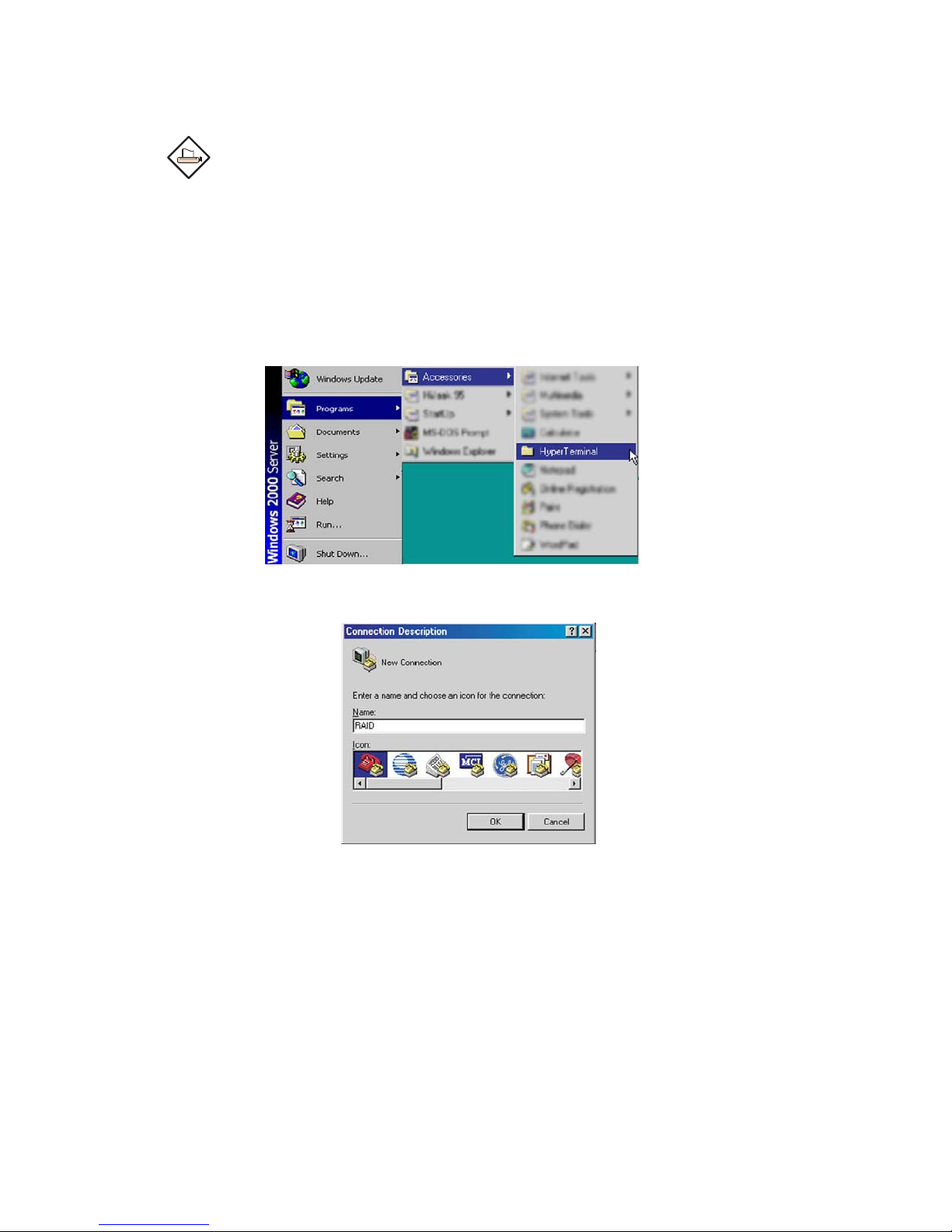
terminal emulation mode to the monitor port located at the rear of the
subsystem.
Note:
You may connect a terminal while the subsystem’s power is on.
2. Power-on the terminal.
3. Run the VT100 program or an equivalent terminal program.
Page 35
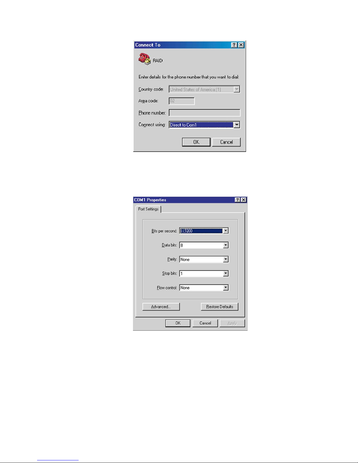
4. The default setting of the monitor port is 115200 baud rate, 8 data bit,
non-parity, 1 stop bit and no flow control.
Page 36
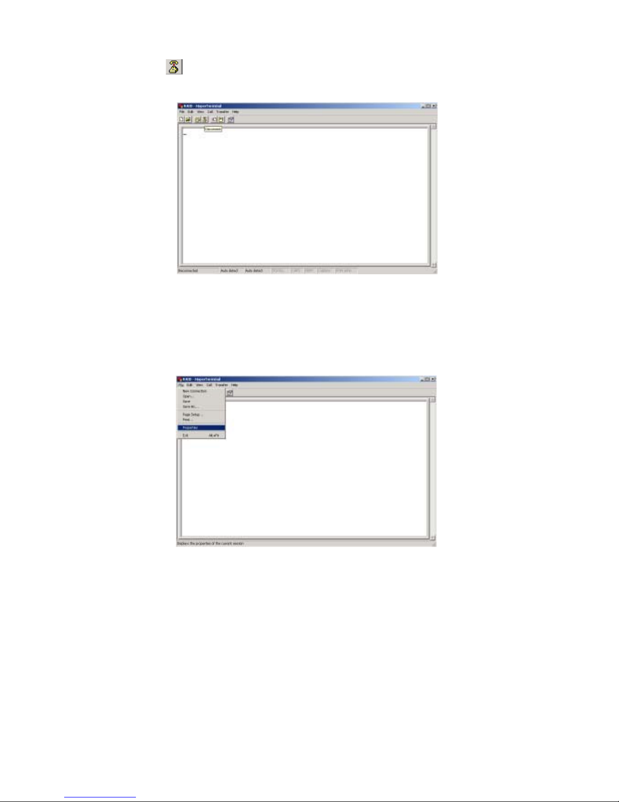
5. Click disconnect button.
6. Open the File menu, and then open Properties.
Page 37
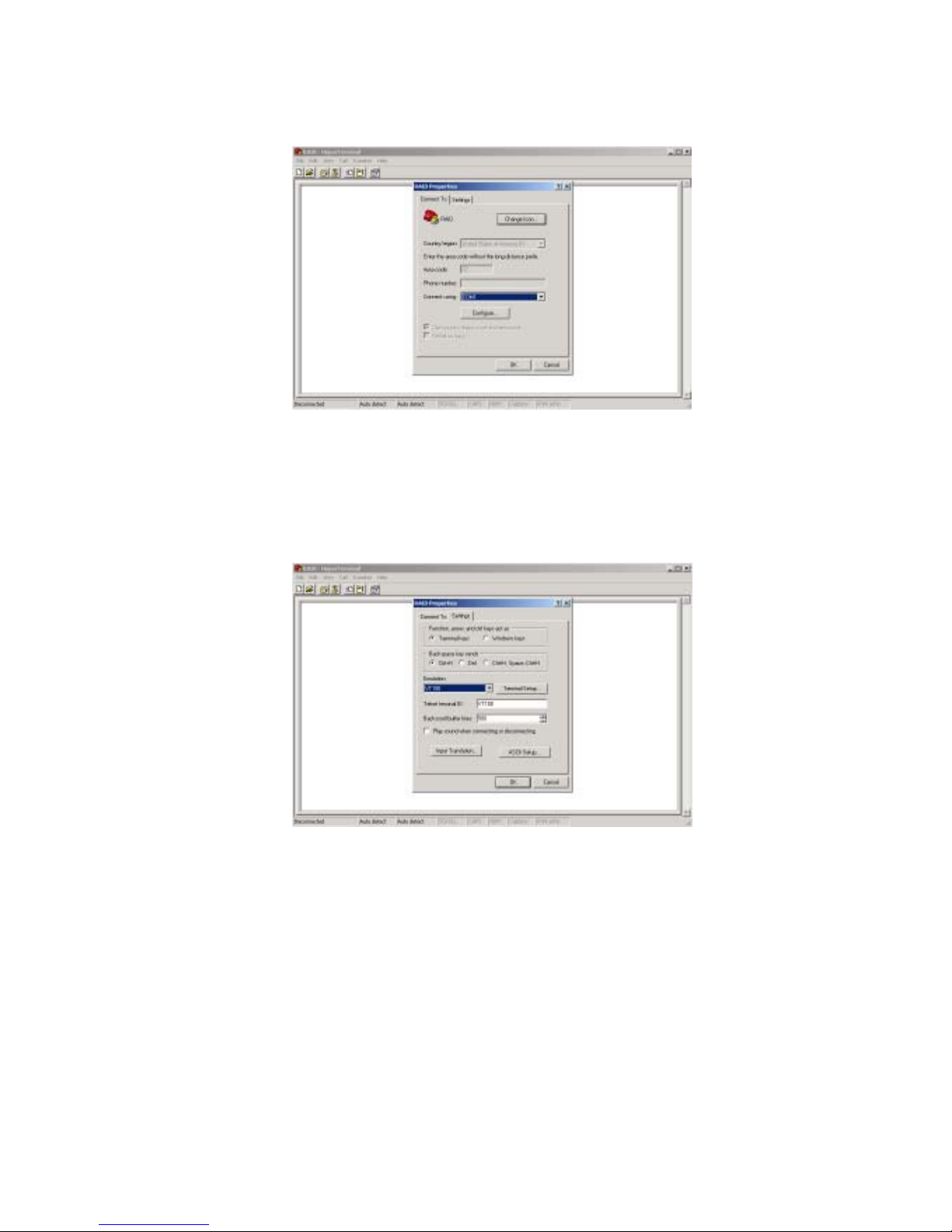
7. Open the Settings Tab.
8. Open the Settings Tab. Function, arrow and ctrl keys act as: Terminal
Keys, Backspace key sends: Crtl+H, Emulation: VT100, Telnet terminal:
VT100, Back scroll buffer lines: 500. Click OK.
Page 38
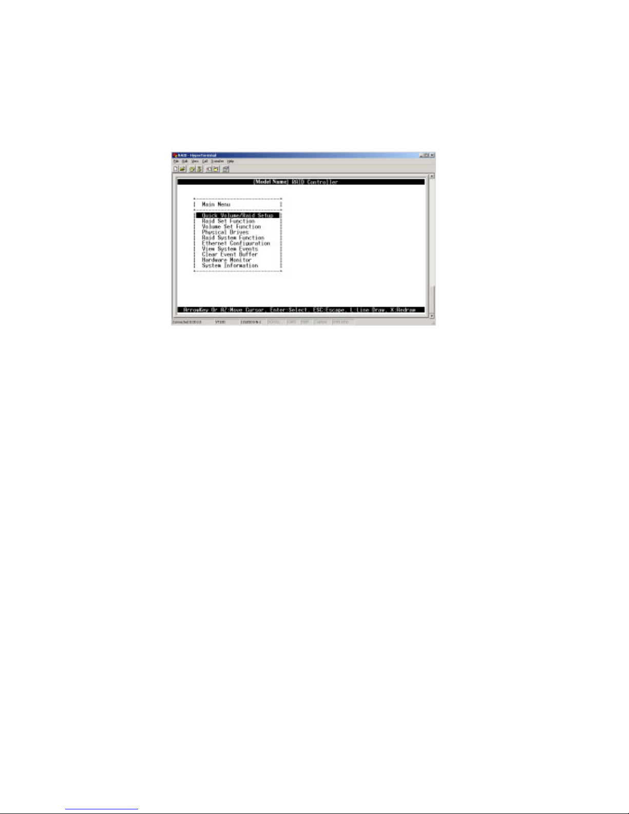
9. Now, the VT100 is ready to use. After you have finished the VT100 Terminal
setup, you may press “ X “ key (in your Terminal) to link the RAID
subsystem and Terminal together. Press “X’ key to display the disk array
Monitor Utility screen on your VT100 Terminal.
10. The Main Menu will appear.
Keyboard Function Key Definitions
“ A “ key - to move to the line above
“ Z “ key - to move to the next line
“ Enter “ key - Submit selection function
“ ESC “ key - Return to previous screen
“ L ” key - Line draw
“ X ” key - Redraw
Page 39
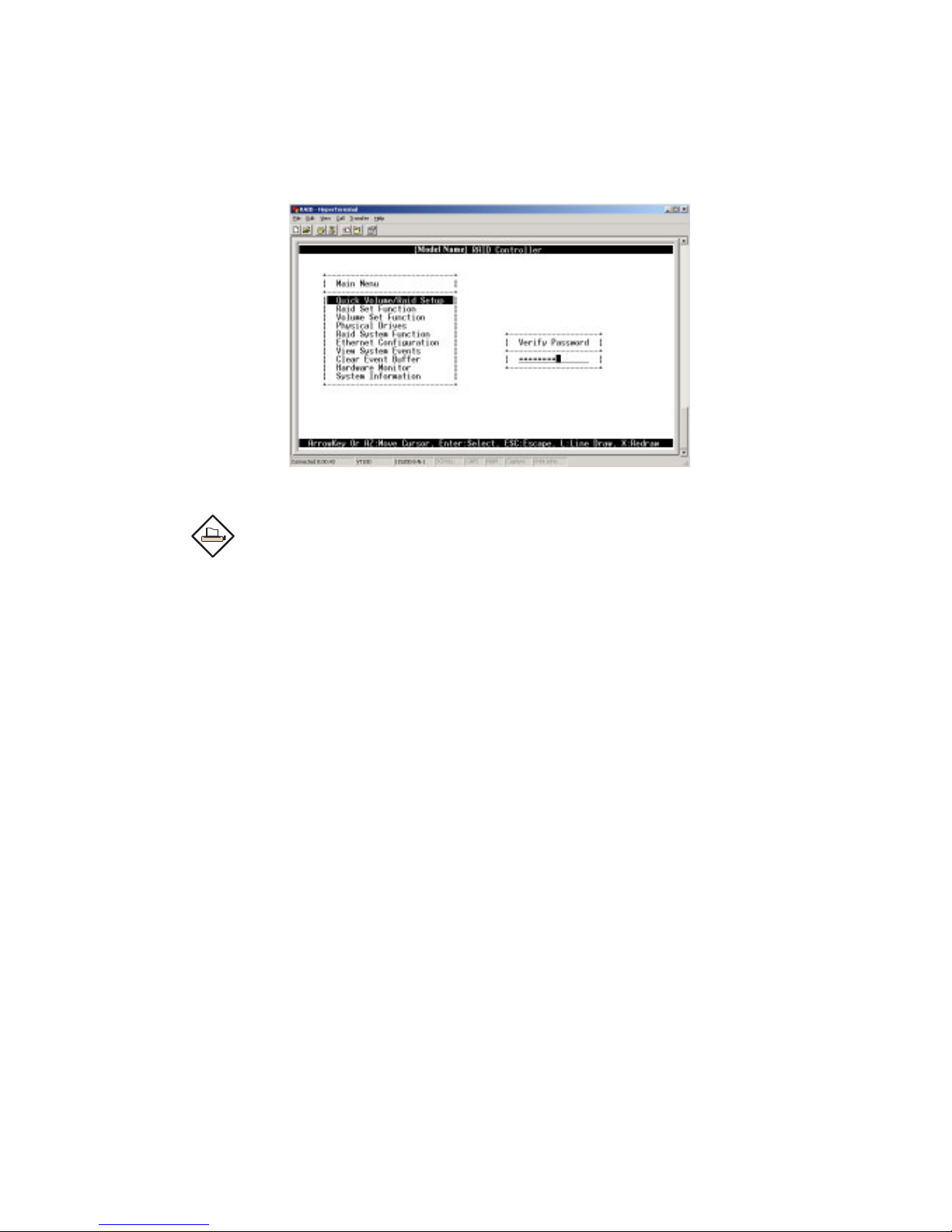
Main Menu
The main menu shows all function that enables the customer to execute
actions by clicking on the appropriate link.
Note:
The password option allows user to set or clear the raid subsystem’s
password protection feature. Once the password has been set, the user
can only monitor and configure the raid subsystem by providing the
correct password. The password is used to protect the internal RAID
sub- system from unauthorized entry. The controller will check the
password only when entering the Main menu from the initial screen.
The RAID subsystem will automatically go back to the initial screen
when it does not receive any command in twenty seconds. The RAID
subsystem password is default setting at 00000000 by the manufacture.
Page 40
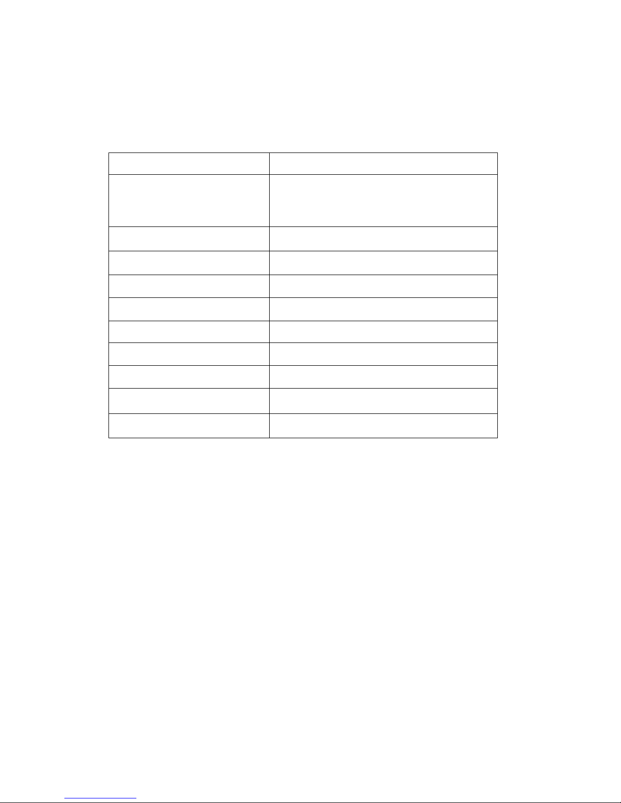
VT100 terminal configuration Utility Main Menu Options
Select an option and the related information or submenu items display beneath it.
The submenus for each item are explained on the section 3.3. The
configuration
Option
utility main menu options are:
Quick Volume And Raid Set
Setup
Raid Set Functions
Description
Create a RAID configurations which is
consist of the number of physical disk
installed
Create a customized raid set
Volume Set Functions
Physical Drive Functions
Raid System Functions
Ethernet Configuration
Views System Events
Clear Event Buffer
Hardware Monitor
System Information
Create a customized volume set
View individual disk information
Setting the raid system configurations
Setting the Ethernet configurations
Record all system events in the buffer
Clear all event buffer information
Show all system environment status
View the controller information
Page 41
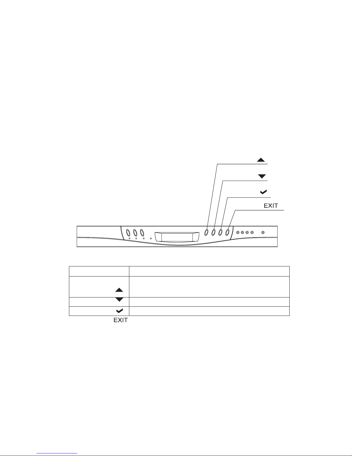
3.2 Configuring the Subsystem Using the LCD Panel
The LCD Display front panel function keys are the primary user interface for
the Disk Array. Except for the “Firmware update”, all configuration can be performed through this interface. The LCD provides a system of screens with
areas for information, status indication, or menus. The LCD screen displays
up to two lines at a time of menu items or other information. The RAID
subsystem password is default setting at 00000000 by the manufacture.
Function Key Definitions
The four function keys at the top of the front panel perform the following
functions:
Up or Down
arrow buttons
Select button
Exit button
Parts
Use the Up or Down arrow keys to go through the information on
the LCD screen. This is also used to move between each
menu when you configure the subsystem.
This is used to enter the option you have selected.
Press this button to return to the previous menu.
Up button
Function
Down button
Select button
Exit button
Page 42
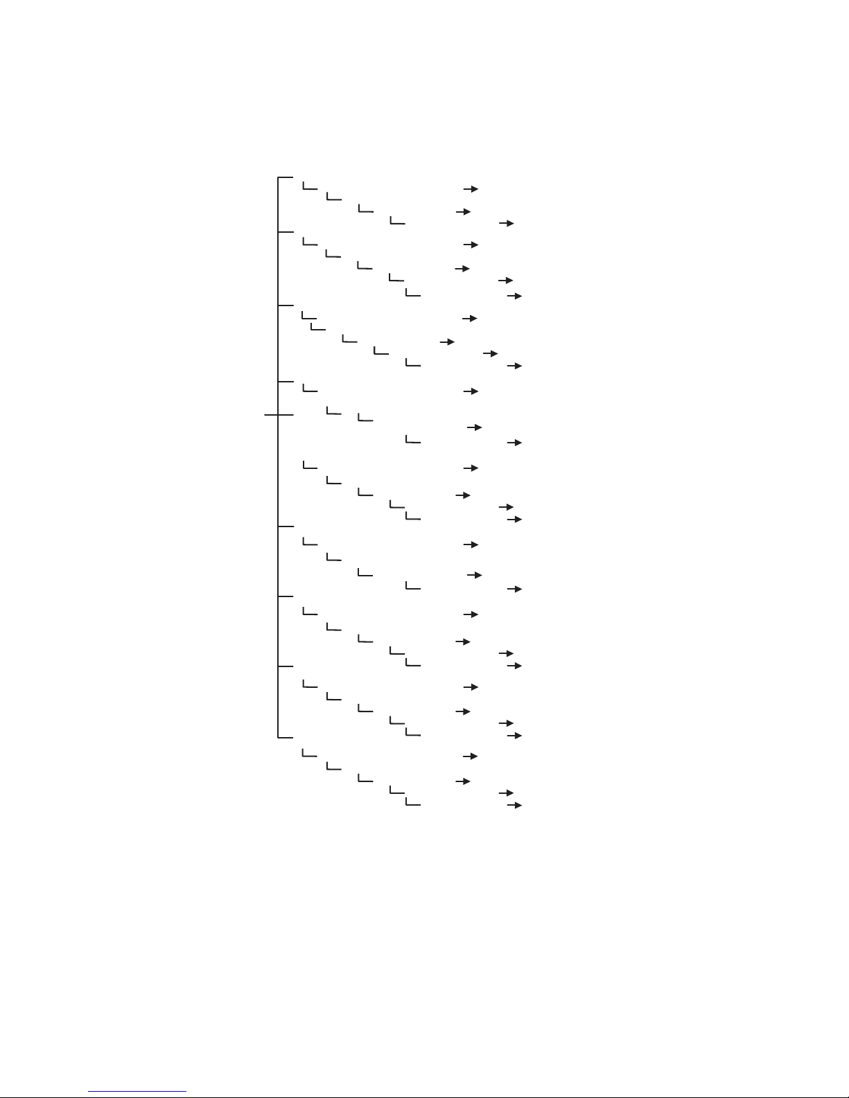
3.3 Menu Diagram
The following tree diagram is a summary of the various parameters, settings
and functions that can be accessed through the LCD panel menus or the
terminal monitor.
Quick Volume /
Raid Setup
Ra id 0
Gre ater Two TB Vol um e Sup port
Sel ecte d Ca pa ci ty
Sel ect St ri pe Si ze
Ra id 1 or 0+ 1
Ra id 1
Ra id 3
Ra id 5
Ra id 3 + Spa re
Ra id 5 + Spa re
Ra id 6
Ra id 6 + Spa re
Gre ater Two TB Vol um e Sup port
Sel ecte d Ca pa ci ty
Sel ect St ri pe Si ze
or
0+ 1 +Sp are
Gre ater Two TB Vol um e Sup port
Sel ecte d Ca pa ci ty
Gre ater Two TB Vol um e Sup port
Sel ecte d Ca pa ci ty
Gre ater Two TB Vol um e Sup port
Sel ecte d Ca pa ci ty
Gre ater Two TB Vol um e Sup port
Sel ecte d Ca pa ci ty
Gre ater Two TB Vol um e Sup port
Sel ecte d Ca pa ci ty
Gre ater Two TB Vol um e Sup port
Sel ecte d Ca pa ci ty
Gre ater Two TB Vol um e Sup port
Sel ecte d Ca pa ci ty
Sel ect St ri pe Si ze
Cre ate Vol / Ra id Set Yes, No
Cre ate Vol / Ra id Set Yes, No
Sel ect St ri pe Si ze
Cre ate Vol / Ra id Set Yes, No
Sel ect St ri pe Si ze
Sel ect St ri pe Si ze
Sel ect St ri pe Si ze
Cre ate Vol / Ra id Set Yes, No
Cre ate Vol / Ra id Set Yes, No
Ini tial iz ati on Mod e
Ini tial iz ati on Mod e
Ini tial iz ati on Mod e
Cre ate Vol / Ra id Set Yes, No
Ini tial iz ati on Mod e
Ini tial iz ati on Mod e
Cre ate Vol / Ra id Set Yes, No
Ini tial iz ati on Mod e
Cre ate Vol / Ra id Set Yes, No
Ini tial iz ati on Mod e
Cre ate Vol / Ra id Set Yes, No
Ini tial iz ati on Mod e
No , Us e 64B it LBA , Us e 4k Bl oc k
4K, 8K,1 6K ,3 2K ,6 4K ,1 28 K
No , Us e 64B it LBA , Us e 4k Bl oc k
4K, 8K,1 6K ,3 2K ,6 4K ,1 28 K
No , Us e 64B it LBA , Us e 4k Bl oc k
4K, 8K,1 6K ,3 2K ,6 4K ,1 28 K
No , Us e 64B it LBA , Us e 4k Bl oc k
No , Us e 64B it LBA , Us e 4k Bl oc k
4K, 8K,1 6K ,3 2K ,6 4K ,1 28 K
No , Us e 64B it LBA , Us e 4k Bl oc k
No , Us e 64B it LBA , Us e 4k Bl oc k
4K, 8K,1 6K ,3 2K ,6 4K ,1 28 K
No , Us e 64B it LBA , Us e 4k Bl oc k
4K, 8K,1 6K ,3 2K ,6 4K ,1 28 K
No , Us e 64B it LBA , Us e 4k Bl oc k
4K, 8K,1 6K ,3 2K ,6 4K ,1 28 K
For egro un d, No
For egro un d, No
For egro un d, Bac kgro und, No Ini t
For egro un d, Bac kgro und, No Ini t
For egro un d, Bac kgro und, No Ini t
For egro un d, Bac kgro und, No Ini t
For egro un d, Bac kgro und, No Ini t
For egro un d, Bac kgro und, No Ini t
Ini tial iz ati on, No Ini t
Ini tial iz ati on, No Ini t
Page 43
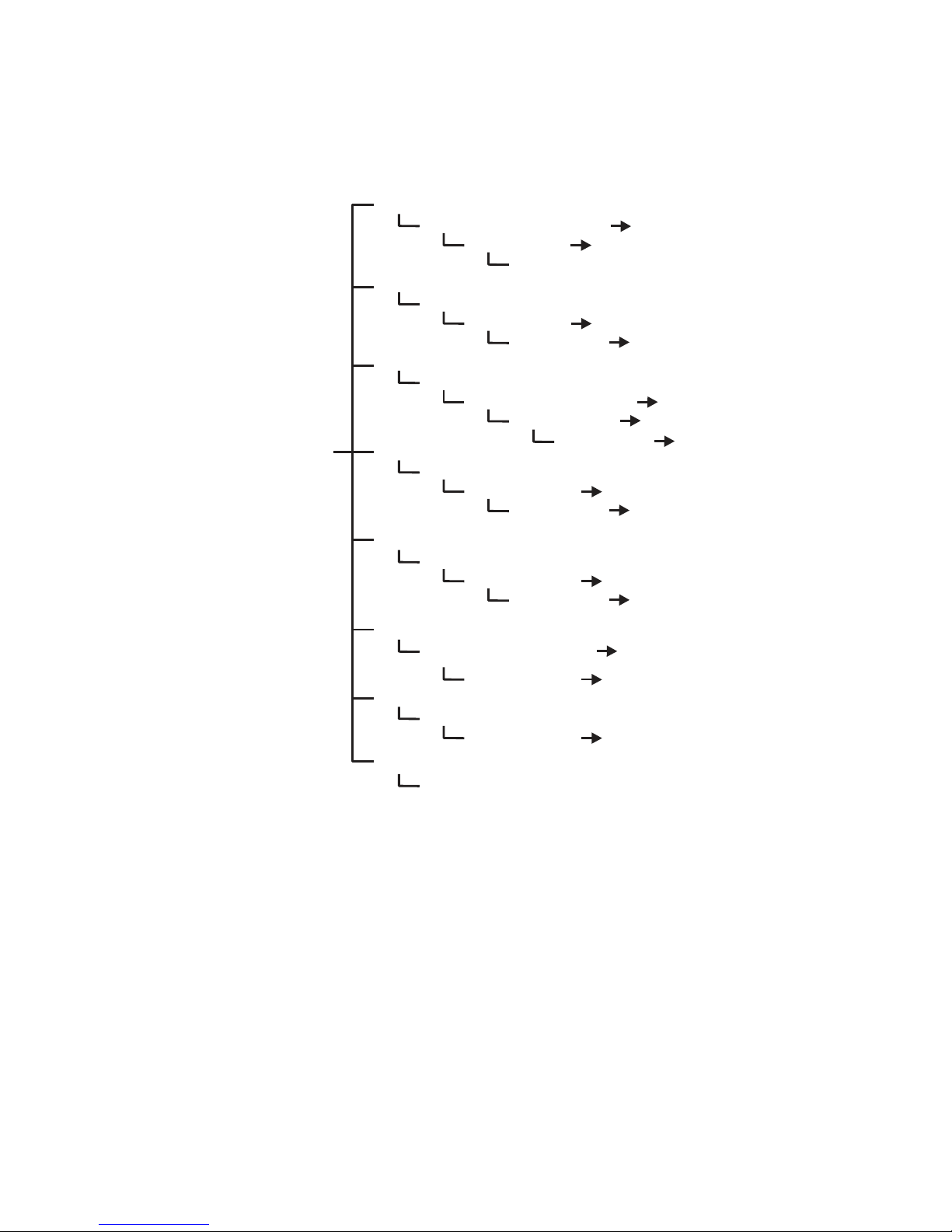
Raid Set Functio n
Creat e
Raid
Set
Se lect IDE
Creat e
Delete
Raid
Set
Se lect
Raid
Delete
Expa nd
Offl ine
Activat e
Creat e Hot Spa re
Delete Hot Spare
Ra id
Raid
Set
Se lect IDE
Se lect
Raid
Set
Se lect
Raid
Offl ine
Raid
Set
Se lect
Raid
Activat e
Se lect
Drives for
Ma x 3 H
Se lect The Hot Spare
Set In format ion
ot
Creat e Hot Spa re
Delete Hot Spare
Se lect
Raid
Drives
for
Raid
Raid
Set
Ed it The
Set To Dele te
Raid
Set
Ar e
you sure ?
Drives
for
Raid
Drives
IDE
Expa nd
Set To Off
Raid
Set
Ar e You S
Set To Activ e
Raid
Set
Ar e You S
Disk
Hot spare ,
spare s
upported
Disk
Set To
Disp lay
Set
Yes, No
Raid
Set
Yes, No
Yes, No
Set E
xpansion
Chan nel
Raid
Set Yes, No
line
Yes, No
ure?
Yes, No
Yes, No
ure?
Yes, No
Yes, No
De vice To Be
Yes, No
Ch 01
Name
Ch xx
Dele ted
Ch xx
~
~
Ch01 6
~
Ch016
Ch016
Page 44
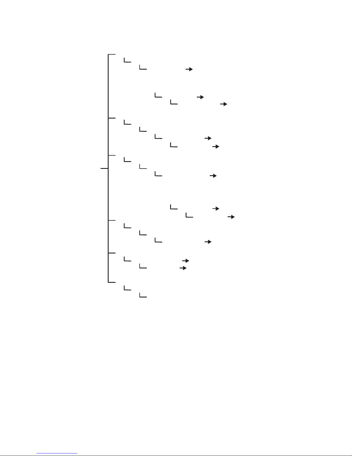
Vol ume Set Fu ncti o n
Cr eat e Vol ume Se t
Cr eat e Vol ume From Raid Set
Delet e Vol ume Se t
Delet e Vol ume From Raid Set
Mo dify Vol ume Set
Mo dify Vol ume From Raid Se t
Ch eck Vol ume Set
Ch eck Vol ume From Raid Set
Stop Vol u me Chec k
Stop All Vol ume Ch eck
Displ ay Vol ume Info.
Displ ay Vol ume Info in Raid
Vol ume Cr eation
Cr eat e Vol ume
Selec t Vol ume To Delet e
Delet e Vol ume Set
Selec t Vol ume To Mo dify
Selec t Vol ume To Ch eck
Ch eck Th e Vol ume Yes , No
Are yo u su re?
Selec t Vol ume To Displ ay
Initi alization Mo de
Are yo u su re?
Vol ume Modi fica tio n
Mo dify Vol ume Yes , No
Yes , No
Yes , No
Great er Two TB Volu me Su ppo r t,
Vol u me Na me, Raid Level ,
Ca pac ity, St rip e Size, SC SI Chann el,
SCSI ID, SCSI LU N, Cache Mo de,
Tag Qu eui n g, Max Sy nc Ra te
Yes , No
Fo reg roun d, Backg roun d, No Init
Yes , No
Yes , No
Are yo u su re?
Great er Two TB Volu me Su ppo r t,
Vol u me Na me, Raid Level ,
Ca pac ity, St rip e Size,
SCSI Ch ann el, SC SI ID ,
SCSI LU N, Cache Mo de,
Tag Qu eui n g, Max Sy nc Ra te
Yes , No
RAID Configuring
Page 45
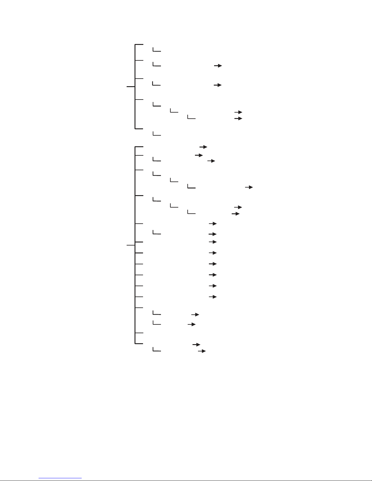
Ph ys i ca l Dr ive s
Ra id Sy st e m Fu nct io n
Vie w Driv e In fo rmati on
Se le ct Th e Driv es
Crea te Pass Th ro ug h Di sk
Se le ct Th e Driv es
Mo di fy Pa ss Thro ug h Di sk
Se le ct Th e Driv es
De le te Pass Th ro ug h Di sk
Se le ct Th e Driv es
De le te Pass Th ro ug h
Id en ti fy Sele ct ed Driv e
Se le ct Th e Driv es
Mu te Th e Aler t Beep er
Al er t Be ep er Se tt in g
Sa ve The Se tt in gs
Ch an ge Pass wo rd
En te r Ne w Pa ss word
Re -E nter Pa ss word
JB OD / RAID Fu nc tio n
RAID , JB OD
Co nf ig u re d AS JB OD ?
Ba ck groun d Task Prio ri ty
Sa ve The Se tt in gs
Ma xi mum SATA Mode
HD D Re ad Ahea d Ca ch e
St ag ge r Powe r on
Sp in
Do wn
Id le
Di sk Writ e Ca ch e Mode
Ca pa ci ty Tru nc a ti on
Term in al Port Co nf ig
Ba ud Ra te
St op Bi ts
Up da te Firm wa re
Re st ar t Co nt ro lle r
Ar e yo u sure ?
Ar e yo u sure ?
Di sa bl ed, Enab le d
Sa ve The Pa ss wo rd
Ar e yo u sure ?
HDD
12 00 ,2400 ,4 80 0 ,9 60 0,
19 20 0, 384 00 ,5 760 0, 115 200
1 bi t, 2 bi ts
Yes , No
SCSI Ch an nel , SCSI ID,
SCSI LU N, Ca ch e Mo de ,
Tag Qu eu ing , Ma x Sy nc Ra te
SCSI Ch an nel , SCSI ID,
SCSI LU N, Ca ch e Mo de ,
Tag Qu eu ing , Ma x Sy nc Ra te
Yes , No
Yes , No
Ul tr aL ow( 5% ), Lo w( 20 %),
Me di um ( 50 %) ,Hi gh (8 0%)
Yes , No
SATA1 50, SATA1 50+ NC Q,
SATA3 00, SATA3 00+ NC Q
En ab le , Di sa bl e Maxt or,
Di sa bl e
0. 4, 0. 7, 1. 0, 1. 5, 2.0, 2. 5,
3. 0, 3. 5, 4. 0, 4. 5, 5.0, 5. 5, 6. 0
Di sa bl e, 1( fo r
15, 20, 30, 40, 50, 60
Au to , Enab le d, Di sa bl ed
To Mu lt ipl es of 10 G,
To
Mu lt ipl es of 1G ,
Di sa bl ed
Yes , No
Yes , No
Yes , No
Yes , No
Yes , No
Yes , No
te st) , 3, 5, 10,
Page 46
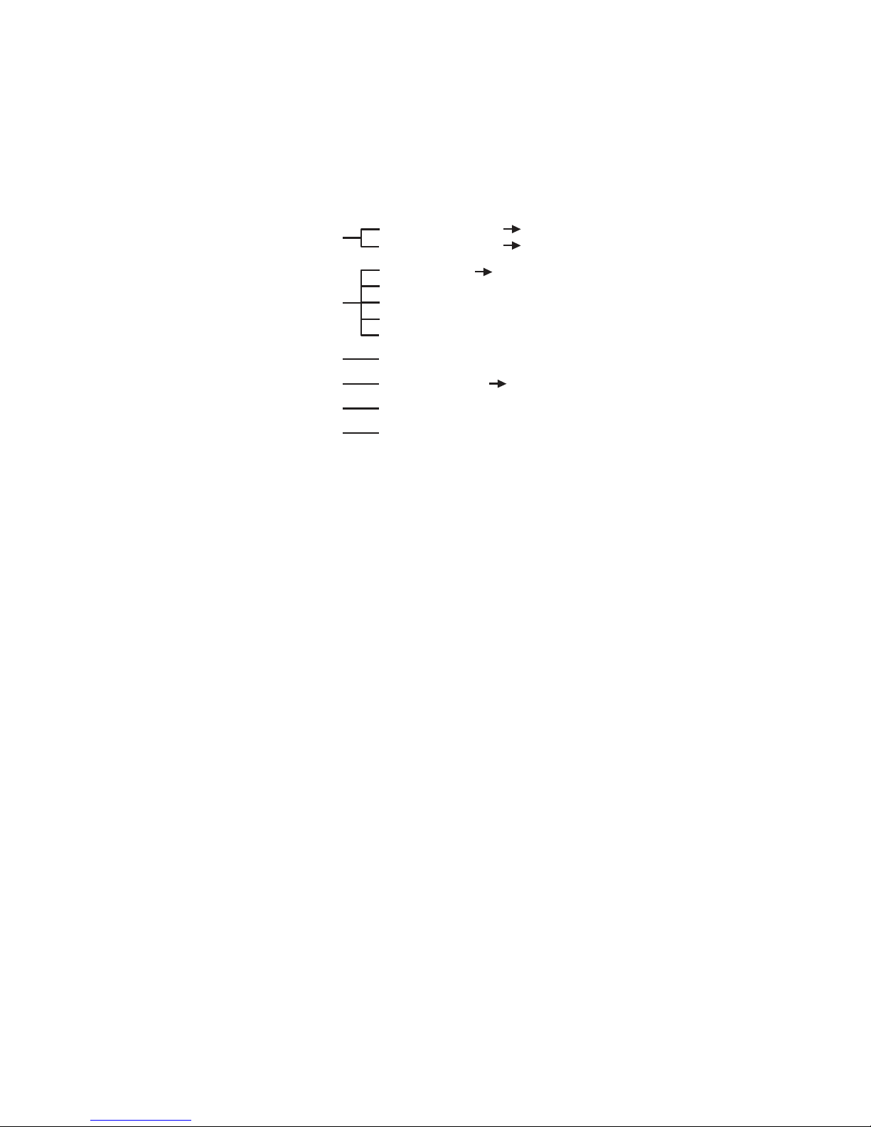
In Ba nd SA S Co nf i g
Et he r ne t Co nf i gu ratio n
View Sy st e m Ev en t s
Cl ea r Ev en t Bu ff er
Ha rd war e Mo ni tor
Sy st e m In fo r ma tio n
Inba nd SAS Func ti on
Inba nd SAS Po rt
DHCP Func ti on
Loc al IP Ad dr es s
HT TP Port Numb er : 80
Telnet Port Nu mb er : 23
SMTP Port Nu mb er : 25
Show Syst em Ev en ts
Cle a r Ev en t Buff er
The Hard Mo ni to r Info rm at ion
The Sy st em Info rm at ion
Dis abl ed , Enab le d
Yes, No
Enable d, Dis abl ed
0, 1
Page 47
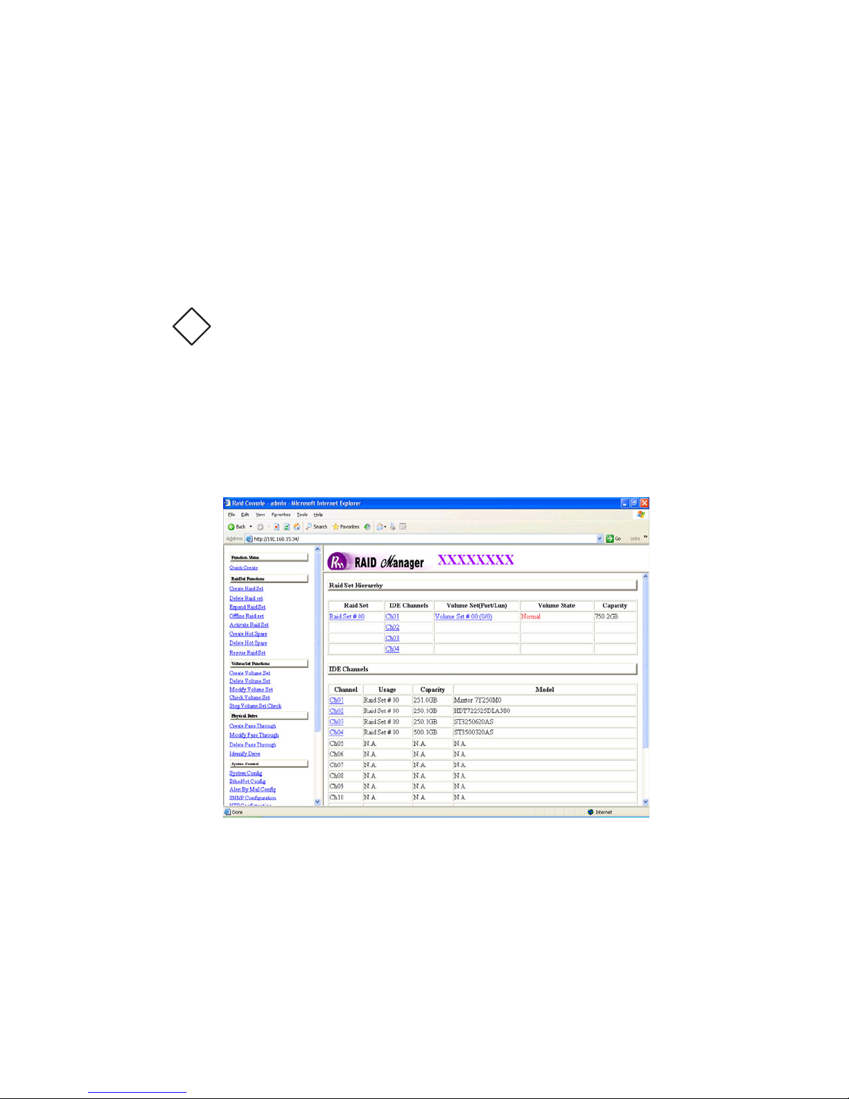
!
3.4 Web browser-based Remote RAID management via R-
Link Ethernet port
Configuration of the internal RAID subsystem with remote RAID management is a
web browser-based application, which utilizes the browser installed on your
operating system. Web browser-based remote RAID management can be used to
man- age all the raid function.
To configure internal RAID subsystem on a remote machine, you need to know its
IP Address. Launch your web browser by entering http://[IP Address] in the remote
web browser.
Important:
The default static IP is “192.168.001.100”. DHCP function is enabled
by default when RAID system is shipped. You can configure correct IP
Address through the LCD panel, serial terminal or through the GUI via the
Note that you must be logged in as administrator with local admin rights on the
remote machine to remotely configure it. The RAID subsystem controller default
User Name is “admin” and the Password is “00000000”.
“Ethernet Configuration” menu.
Page 48
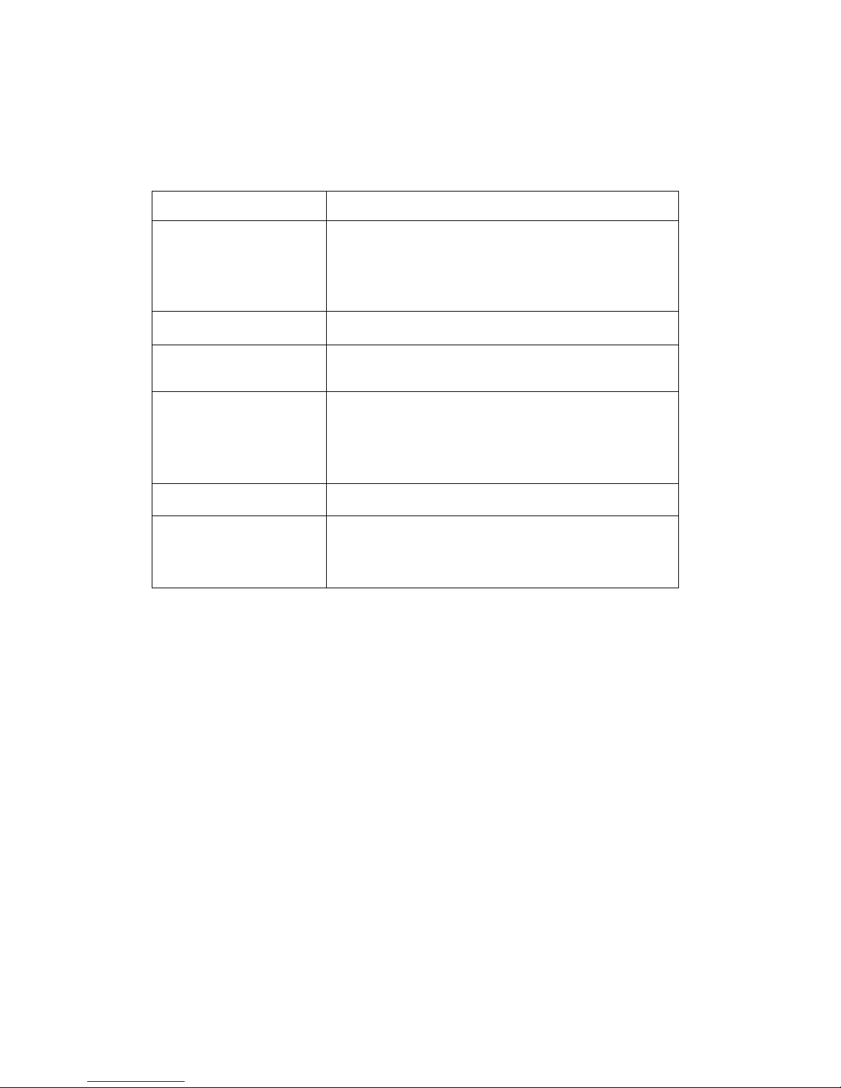
Main Menu
The main menu shows all function that enables the customer to execute
actions by clicking on the appropriate link.
Individual Category
Quick Create
Raid Set Functions
Volume Set Functions
Physical Drive
System Control
Information
Description
Create a RAID configuration, which consists of
the total number of unused physical disk
installed; can modify the volume set Capacity,
Raid Level, and Stripe Size.
Create a customized raid set.
Create customized volume sets and modify the
existed volume sets parameter.
Create pass through disks and modify the
existed pass through drives parameter. It also
provides the function to identify the respect disk
drive.
Setting the raid system configurations
View the controller and hardware monitor
information. The Raid Set Hierarchy can also
view through the Raid Set Hierarchy item.
Page 49
Configuration Procedures
Below are a few practical examples of concrete configuration procedures.
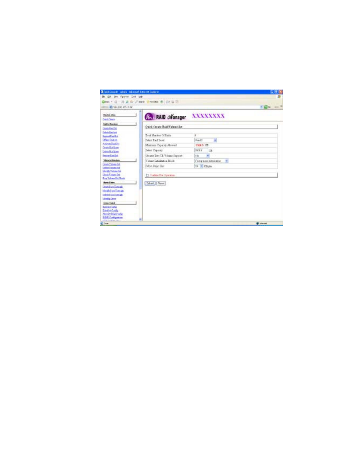
3.5 Quick Create
The number of physical drives in the raid subsystem determines the RAID
levels that can be implemented with the raid set. You can create a raid set
associated with exactly one volume set. The user can change the raid level,
capacity, Volume Initialization Mode and stripe size. A hot spare option is also
created depending upon the existing configuration.
If volume size over 2TB, it will be provided one option “Create 2TB Volume
Support” shown in the above menu. There are three settings for this option
“No”, “64bit LBA”, “4K Block”.
Page 50

Greater Two TB Volume Support:
No: still keep the volume size with max = 2TB Volume Set limitation.
64bit LBA: the max size = 512TB, for UNIX, Linux kernel 2.6> and Windows
2003>.
4K Block: the max size = 16TB, used with “basic disk manager “under OS
Window 2000, 2003 or XP. Noted that can’t be used by with dynamic disk
manager.
Check off on the Confirm t he Operation and click on the Submit button in
the Quick Create screen, the raid set and volume set will start to initialize.
Note: In Quick Create your volume set is automatically configured based on the
number of disks in your system. Use the Raid Set Function and Volume Set
Function if you prefer to customize your system.
Page 51
3.6 Raid Set Functions
Use the Raid Set Function and Volume Set Function if you prefer to customize
your system. Select the Raid Set Function to manually configure the raid set for
the first time, deleting o r e dit i ng existing raid set(s). A raid set is a group of
disks containing one or more volume sets.
3.6.1 Create Raid Set
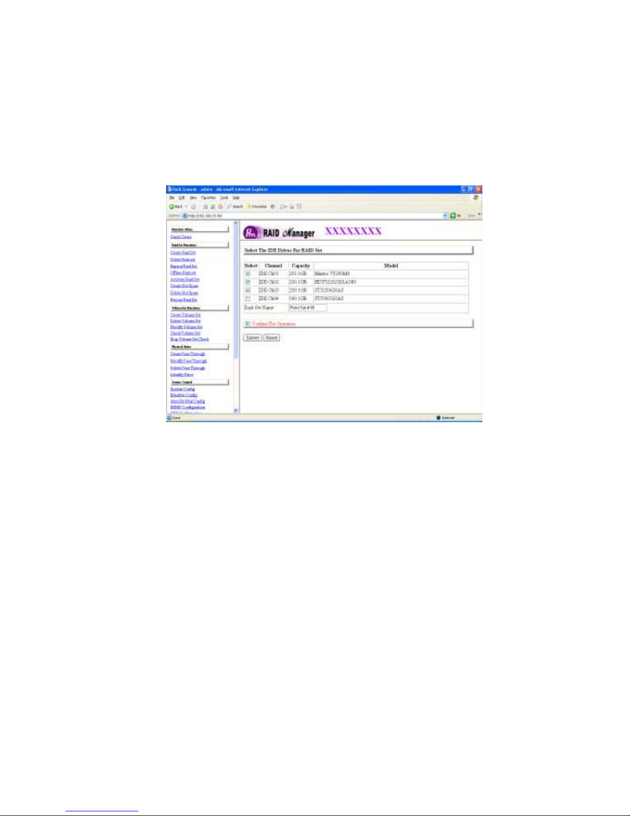
To create a raid set, click on the Create Raid Set link. The “Select the
IDE Drive for RAID Set” screen is displayed showing the IDE drives
connected to the current controller. Click on and s elect th e physical drives
yo u wa n t f or t he current raid set. If d esi red , enter 1 to 15
alphanumeric characters to define a unique nam e for a raid set. The default
raid set name will always appear as Raid Set # XX.
Check the Confirm the Operation and click on the Submit button in the
screen, the raid set will start to initialize.
Page 52
3.6.2 Delete Raid Set
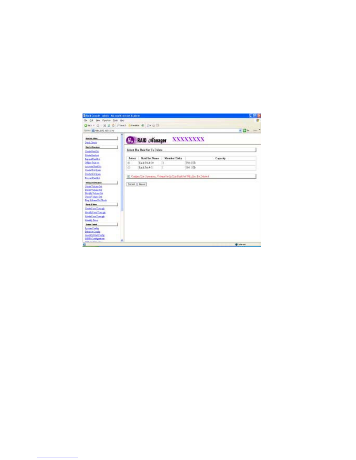
To delete a raid set, click on the Delete Raid Set link. The “Select the RAID
SET to Delete” screen is displayed showing all raid set existing in the current
controller. Select the raid set number you which to delete in the selection column.
Check the Confirm the Operation and click on the Submit button in the
screen to delete the RAID set.
Page 53
3.6.3 Expand Raid Set
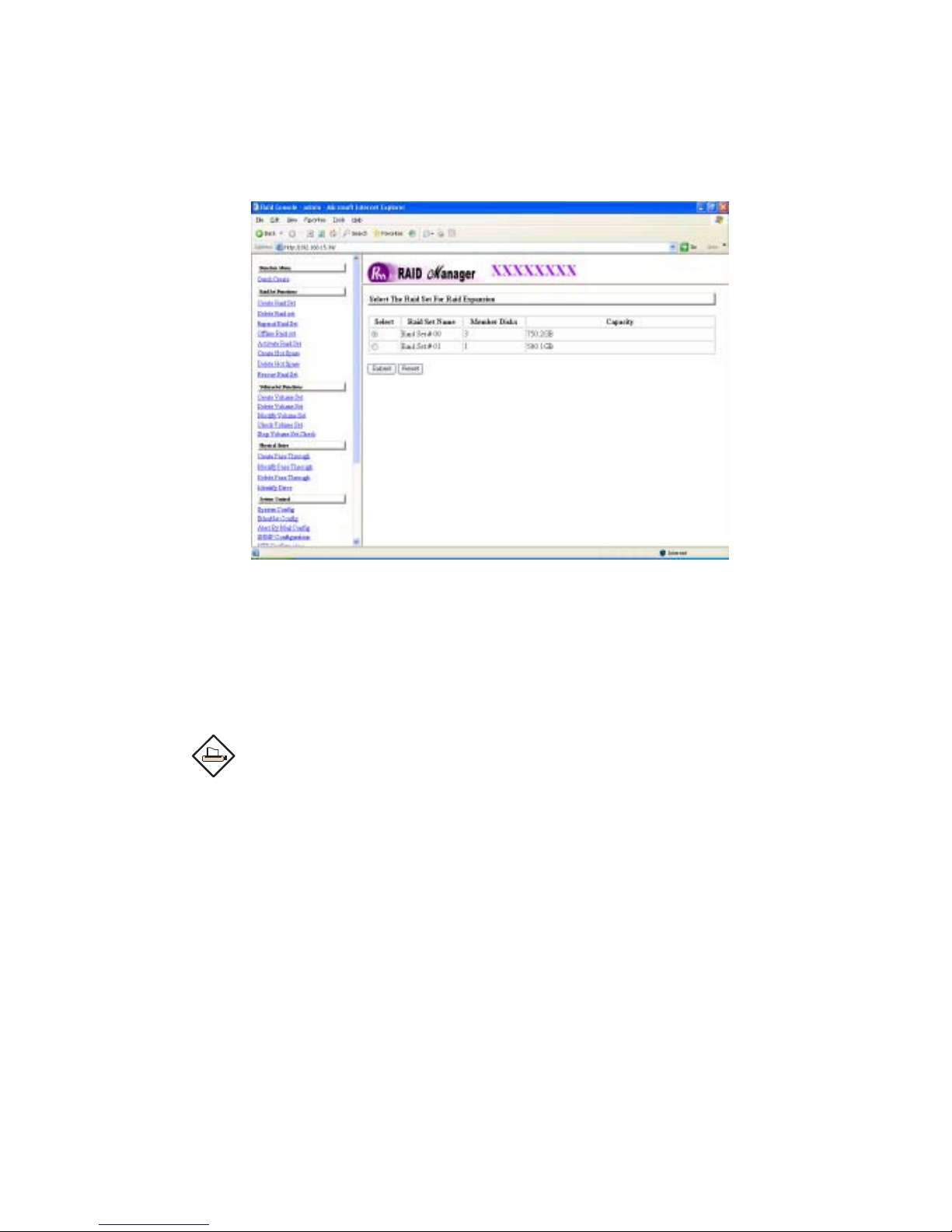
Use this option to expand a raid set, when a disk is added to your system.
This function is active when at least one drive is available.
To expand a raid set, click on the Expand Raid Set link. Select the target raid
set, which you want to expand.
Check on the available disk(s) and Check the Confirm the Operation, and
then click on the
Submit button in the screen to add disks to the raid set.
Note:
1. Once the Expand Raid Set process has started, user cannot
stop it. The process must be completed.
2. If a disk drive fails during raid set expansion and a hot spare is
available, an auto rebuild operation will occur after the raid set
expansion completes.
Page 54
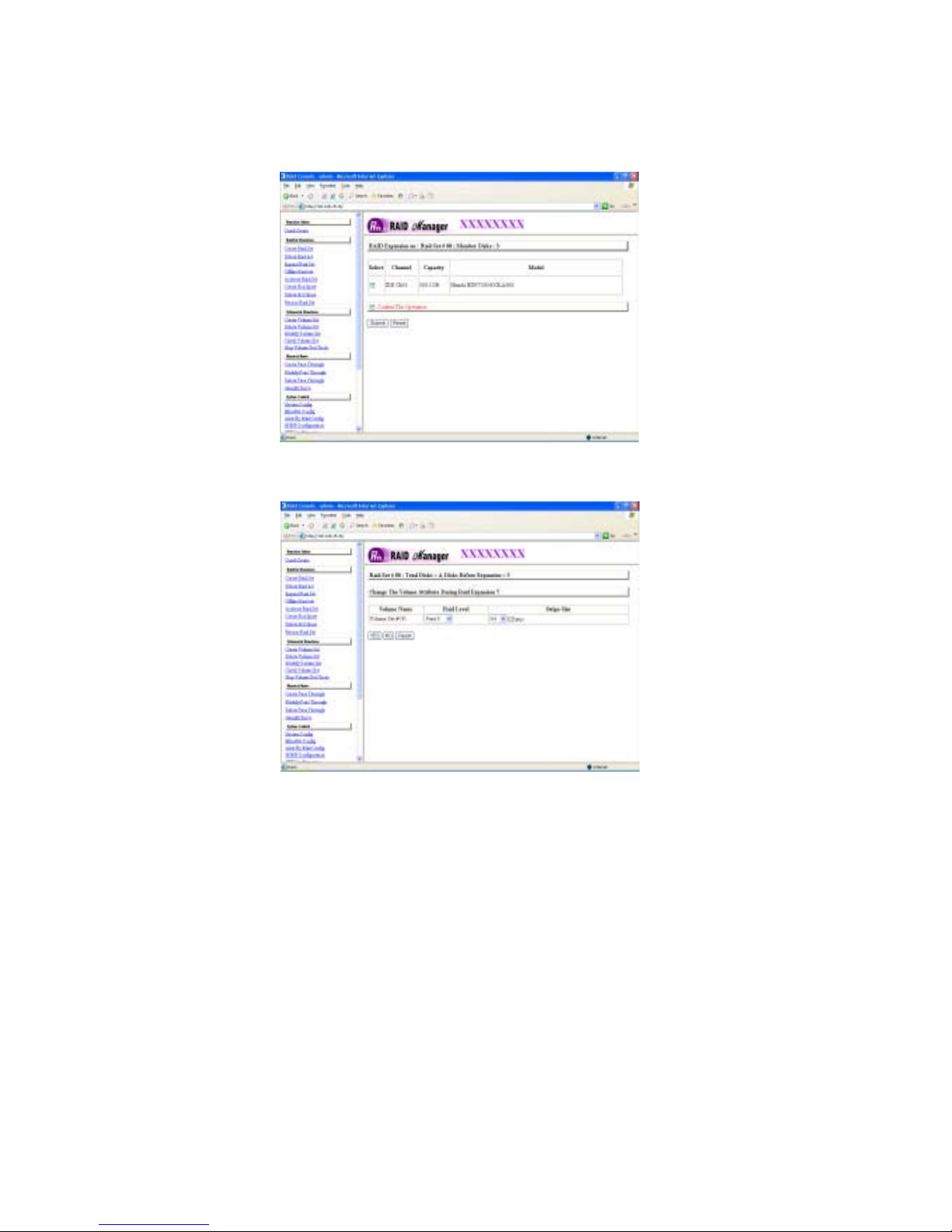
A migrating occurs when a disk is added to a raid set. Migration status is
displayed in the raid status area of the Raid Set information where the disk has
been added to a raid set. Migrating status is also displayed in the associated
volume status area of the volume set Information when a disk is added to a raid
set.
Page 55
3.6.4 Offline Raid Set
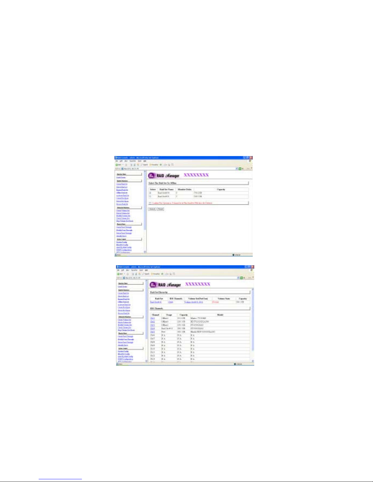
A user can move a Raid Set (group of disk drives) to another RAID system
with the power on. User can use the Offline Raid Set option to offline the
raid set. After user complete the offline function, the HDD State will change to
offline Mode.
To offline a raid set, click on the Offline Raid Set link. The “Select the RAID
SET to Offline” screen is displayed showing all raid set existing in the current
controller. Select the raid set number you wish to offline in the select column.
Check the Confirm the Operation, and then click on the Submit button in the
screen to offline the raid set. The drive slots of the RAID set will turn amber color
indicating the disk drives are ready to be removed from the RAID system.
Page 56
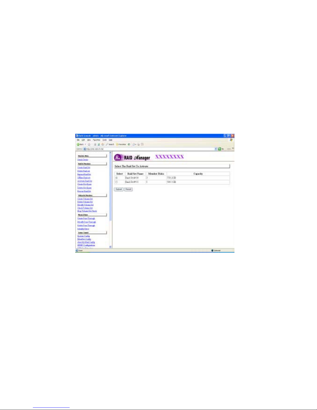
3.6.5 Activate Incomplete Raid Set
When one of the disk drive is removed in power off state or a disk drive has
failed after power cycling, on power up of the RAID system the raid set state
will change to incomplete state and will display on the front panel. If the user
wants to continue using to RAID set after the RAID subsystem is power on,
a user can use the “Activate Raid Set” option to active the raid set. After
user complete the function, the Raid State will change to a Degraded Mode.
To activate an incomplete the raid set, click on the “Activate Raid Set” link,
the “Select the RAID SET to Activate” screen is displayed showing all raid set
existing in the current controller. Select the raid set number you which to activate
in the select column.
Page 57
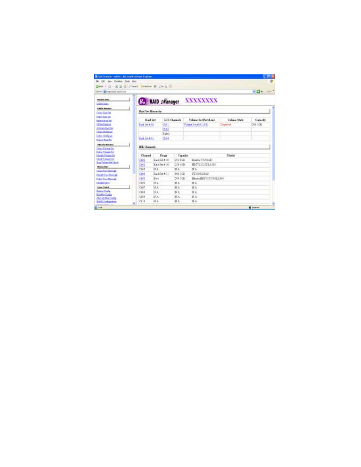
Click on the Submit button in the screen to activate the incomplete
raid set. The RAID se t will continue to work in degraded mode.
Page 58
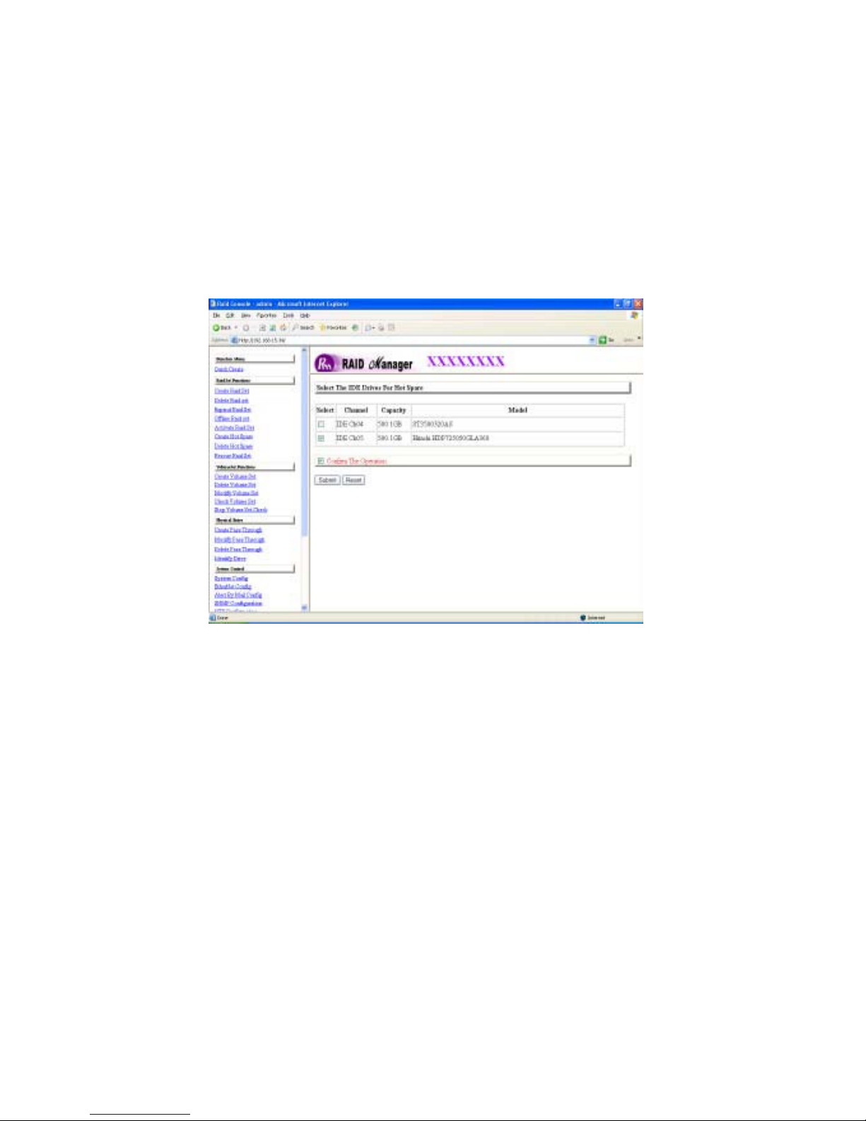
3.6.6 Create Hot Spare (Global only)
The “Create Hot Spare” option gives you the ability to define a global hot
spare.
When you choose the “Create Hot Spare” option in the Raid Set Function, all
the unused physical devices connected to the current controller wil l appear:
Select the target disk by clicking on the appropriate check box. Check the
Confirm the Operation, and click on the Submit button in the screen to
create the hot spare(s).
Page 59
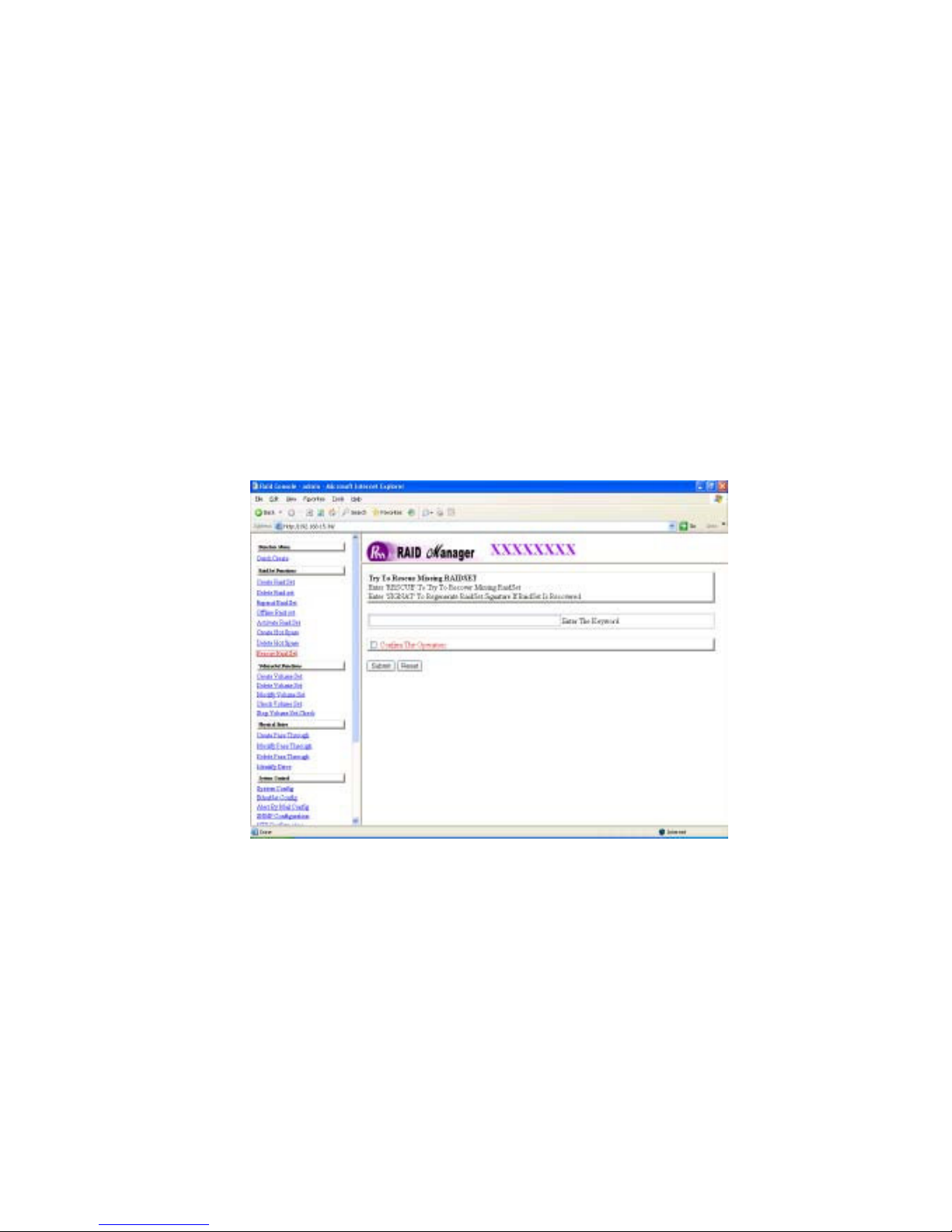
3.6.7 Delete Hot Spare
When you choose the “De let e Hot Spare” option in the Raid Set Function,
all the configured hot spare disk drives connected to the current controller wil l
appear.
Select the target Hot Spare disk to delete by clicking on the appropriate check
box. Check the Confirm the Operation, and click on the Submit button in
the screen to delete the hot spare(s).
3.6.8 Rescue Raid Set
If you need to recover a missing RAID Set, please contact a Partners Data Support
engineer for assistance.
Page 60

3.7 Volume Set Function
A volume set is seen by the host system as a single logical device. It is
organized in a RAID level with one or more physical disks. RAID level refers
to the level of data performance and protection of a volume set. A volume set
capacity can consume all or a portion of the disk capacity available in a
raid set. Multiple volume sets can exist on a group of disks in a raid set.
Additional volume sets created in a specified raid set will reside on all the
physical disks in the raid set. Thus each volume set on the raid set will have
its data spread evenly across all the disks in the raid set.
3.7.1 Create Volume Set
The following is the volume set features:
1.) Volume sets of different RAID levels may coexist on the same raid set.
2.) Up to 16 volume sets in a raid set can be created by the RAID subsystem
controller.
To create volume set from raid set system, go to the main menu and click
on the Create Volume Set link. The “Select the Raid Set” screen will show
all raid sets. Check on a raid set that you want to create and then click on the
Submit button.
The new create volume set allows user to select the Volume name, capacity,
RAID level, strip size, SAS Port/LUN, Cache mode, and tag queuing.
Page 61
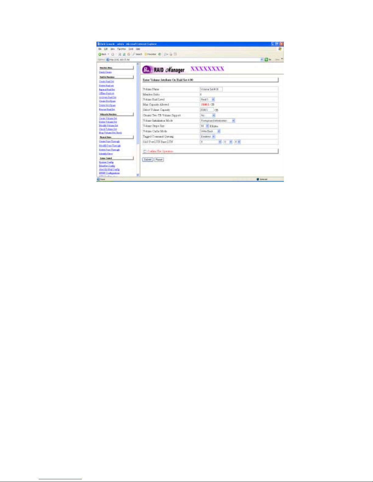
Volume Name:
The default volume name will always appear as Volume Set. #. You can rename the volume set name providing it does not exceed the 15 characters limit.
Raid Level:
Set the RAID level for the Volume Set by clicking of the pull down menu to view
available RAID levels.
The available RAID levels for the current Volume Set are displayed. Select a
RAID level by clicking on it.
Capacity:
The maximum volume size is displayed by default. Enter the desired volume
size to fit your application.
Greater Two TB Volume Support: If volume size i s over 2TB, it will be
provided three options for “Greater 2TB Volume Support”.
No: still keep the volume size with max = 2TB limitation.
Page 62

64bit LBA: the max size = 512TB, for UNIX , Linux 2.6> kernel, Windows 2003>.
4K Block: the max size = 16TB, just use with “basic disk manager “ under OS
Window 2000, 2003 or XP. Noted that can’t be used by with dynamic disk
manager.
Initialization Mode:
Set the “Initialization Mode” for the Volume Set. Foreground mode is faster
completion and background is instant available. No init mode is for rescuing
volume. If you try to Rescue Missing volume set, please contact a
Partners Data System support engineer for assistance.
Strip Size:
This parameter sets the size of the stripe written to each disk in a RAID 0, 1,
0+1, 5 or 6 logical drive. You can set the stripe size to 4KB, 8KB, 16KB, 32KB,
64KB, or 128KB.
A larger stripe size produces better read performance, especially if your
computer does mostly sequential reads. However, if you are sure that your
computer does random reads more often, select a small stripe size
Note: RAID level 3 can’t modify strip size.
Cache Mode:
The RAID subsystem supports Write-Through Cache and Write-Back Cache.
Tag Queuing:
The Enabled option is useful for enhancing overall system performance under
multi-tasking operating systems. The Command Tag (Drive Channel) function
controls the SAS command tag queuing support for each drive channel. This
function should normally remain enabled. Disable this function only when using
older SAS drives that do not support command tag queuing
SAS Port/LUN Base/LUN:
SAS Port: Two 3Gbps SAS channel can be applied to the internal RAID
subsystem
. Choose the SAS Port# option 0, 1 and 0&1 cluster.
Page 63
LUN Base: Each SAS device attached to the SAS card, as well as the card
itself, must be assigned a unique SAS ID number. A SAS channel can connect
up to 128 (0 to 127) devices. The RAID subsystem is as a large SAS device
and should be assign an LUN base from a list of SAS LUNs.
LUN: Each SAS LUN base can support up to 8 LUNs. Most SAS Channel
host adapter treats each LUN like a SAS disk.
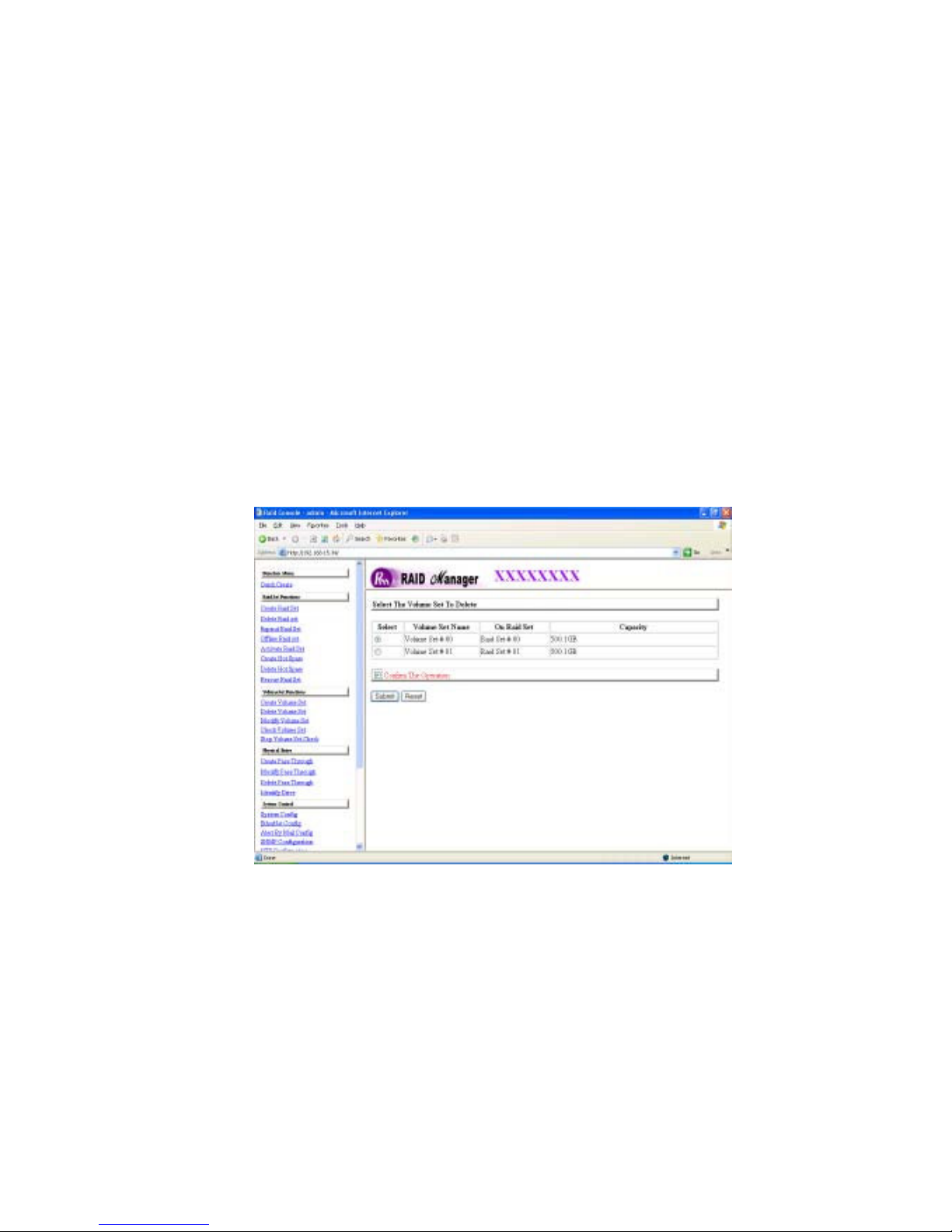
3.7.2 Delete Volume Set
To delete Volume Set from raid set system function, Go t o the main menu
and click on the Delete Volume Set link. The “ Select t he Volume Set to
Delete from RAID set” screen will show all raid sets. Se le ct th e raid set
containing the Volume Set you wish to delete and check the Confirm the
Operation and then click on the Submit button to show all volume sets in the
selected RAID set. S elec t th e volume set number and ch eck the
Confirm the Operation and then click on the Submit button to delete the
volume set.
Page 64

3.7.3 Modify Volume Set
To modify a volume set from a raid set:
(1). Click on the Modify Volume Set link from the main menu.
(2). Select the volume set from the list that you wish to modify. Click on the
Submit button.
The following screen appears.
Use this option to modify volume set configuration. To modify volume set attribute
values from raid set system function, move the cursor bar to the volume set attribute menu and click on it. The modify value screen appears. Move the cursor
bar to an attribute item, and then click on the attribute to modify the value. After
you complete the modification, Check the Confirm the Operation and click on
the Submit button to complete the action. User can modify all values except the
capacity.
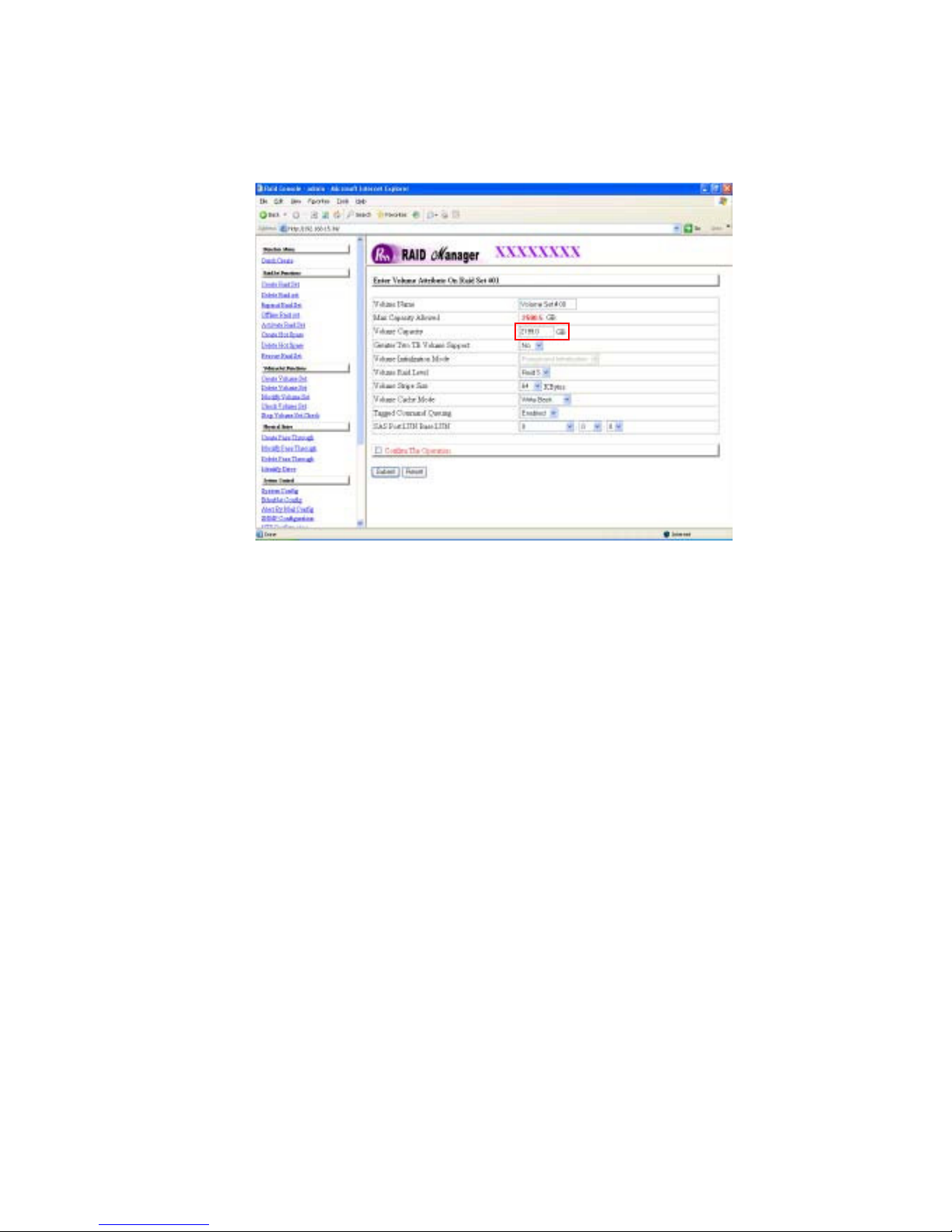
3.7.3.1 Volume Expansion
Volume Capacity (Logical Volume Concatenation plus Re-Stripe)
Use this raid set expands to expand a raid set, when a disk is added to your
system. (Refer to section 3.6.3)
The expand capacity can use to enlarge the volume set size or create another
volume set. The modify volume set function can support the volume set
expansion function. To expand volume set capacity value from raid set system
function, move the cursor to the volume set Volume capacity item and enter
the desired capacity size.
Check on the Confirm the Operation and click on the Submit button to
complete the action. The volume set start to expand.
Page 65
Page 66
3.7.4 Volume Set Migration
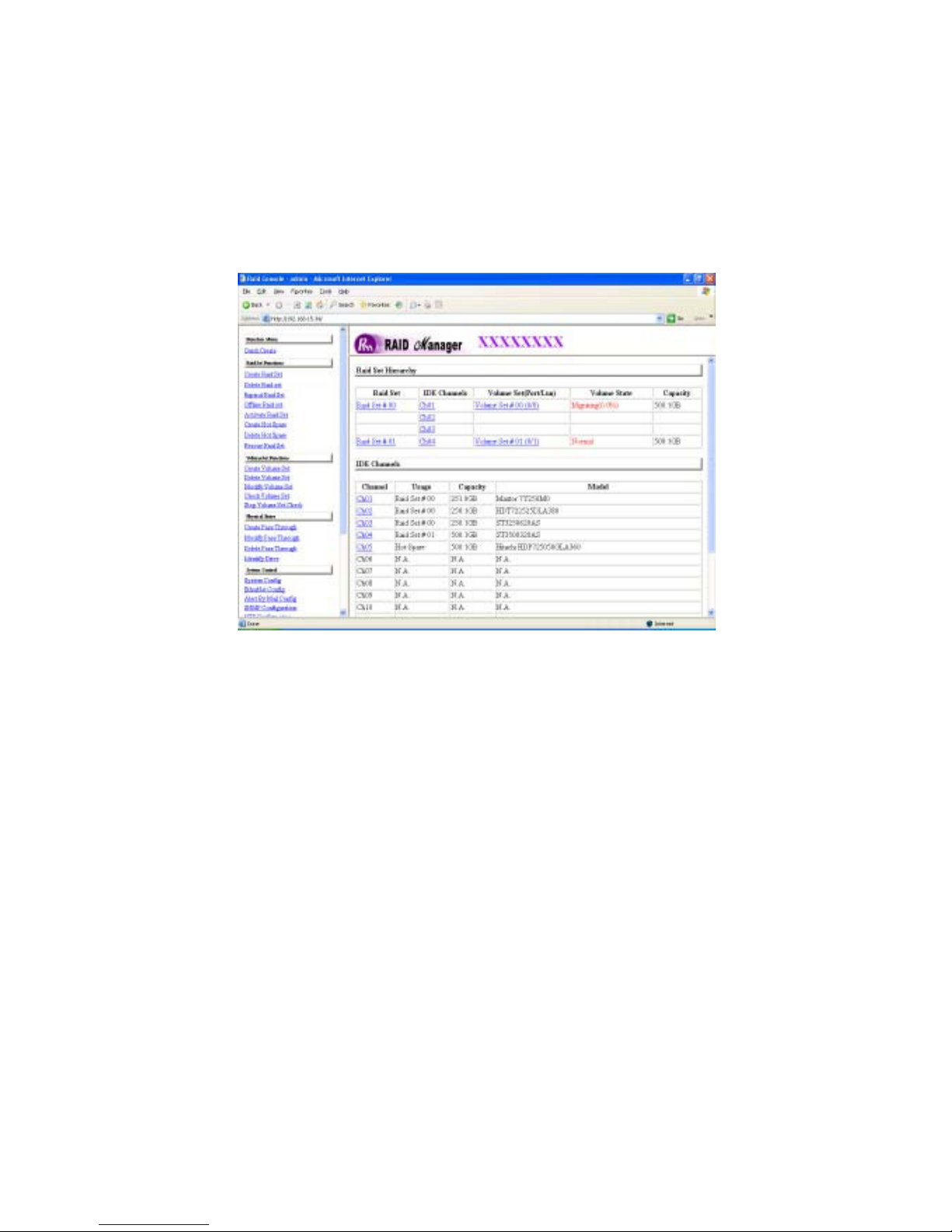
Migrating occurs when a volume set is migrating from one RAID
level to another, a volume set strip size changes, or when a disk is added
to a raid set. Migration status is displayed in the volume status area of the
Raid Set Hierarchy (Main Menu) screen when one RAID level to another, a
Volume set strip size changes or when a disk is added to a raid set.
Page 67
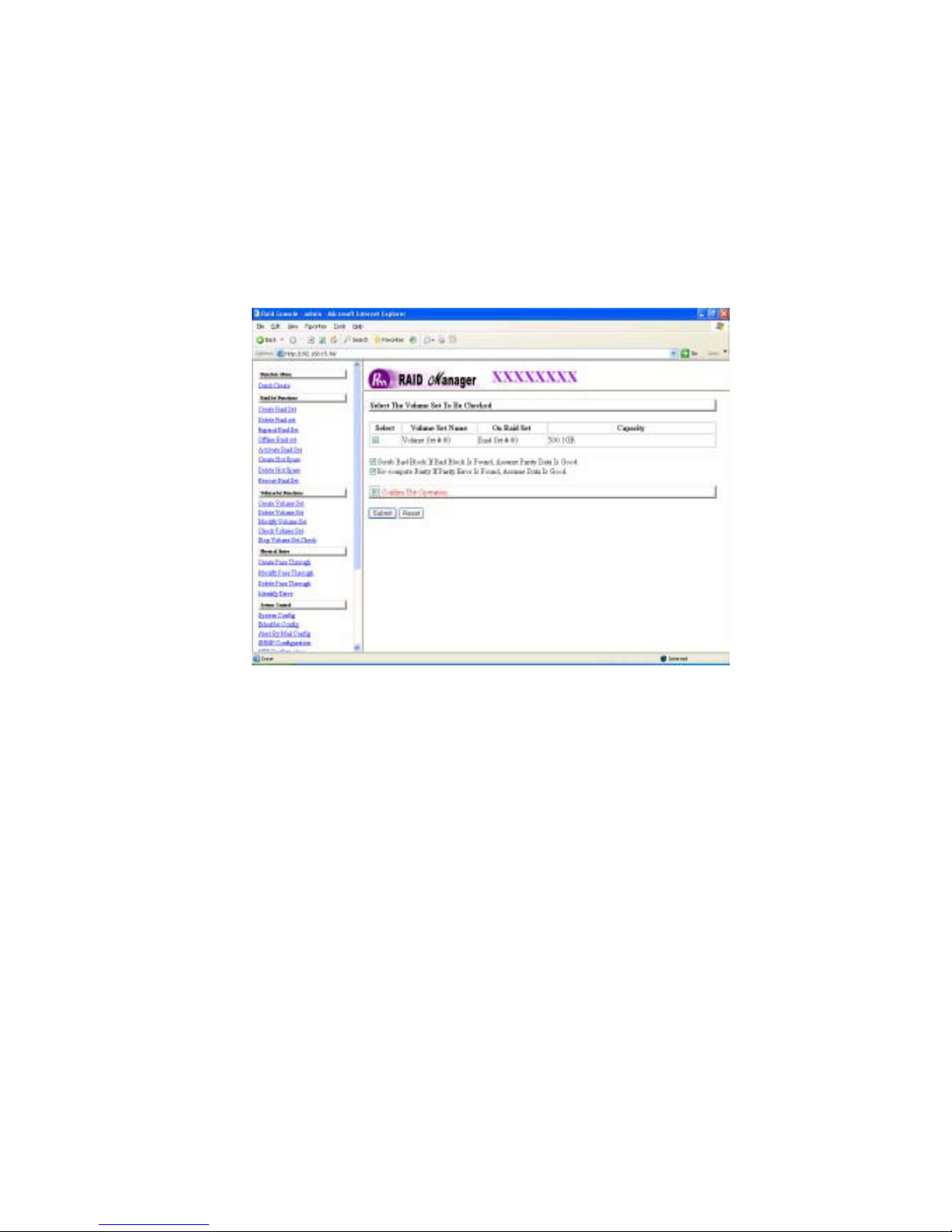
3.7.5 Check Volume Set
To parity check a volume set from a raid set:
(1). Click on the Check Volume Set link.
(2). Select the volume set from the list that you wish to check. Check the
Confirm the Operation and click on the Submit button.
Use this option to verify the correctness the redundant data (Parity) in a volume
set. For example, in a RAID Set with dedicated parity, volume set check means
computing the parity of the data disk drives and comparing the results to the
contents of the dedicated parity disk drive. The checking percentage can also
be viewed by clicking on Raid Set Hierarchy in the main menu.
Page 68
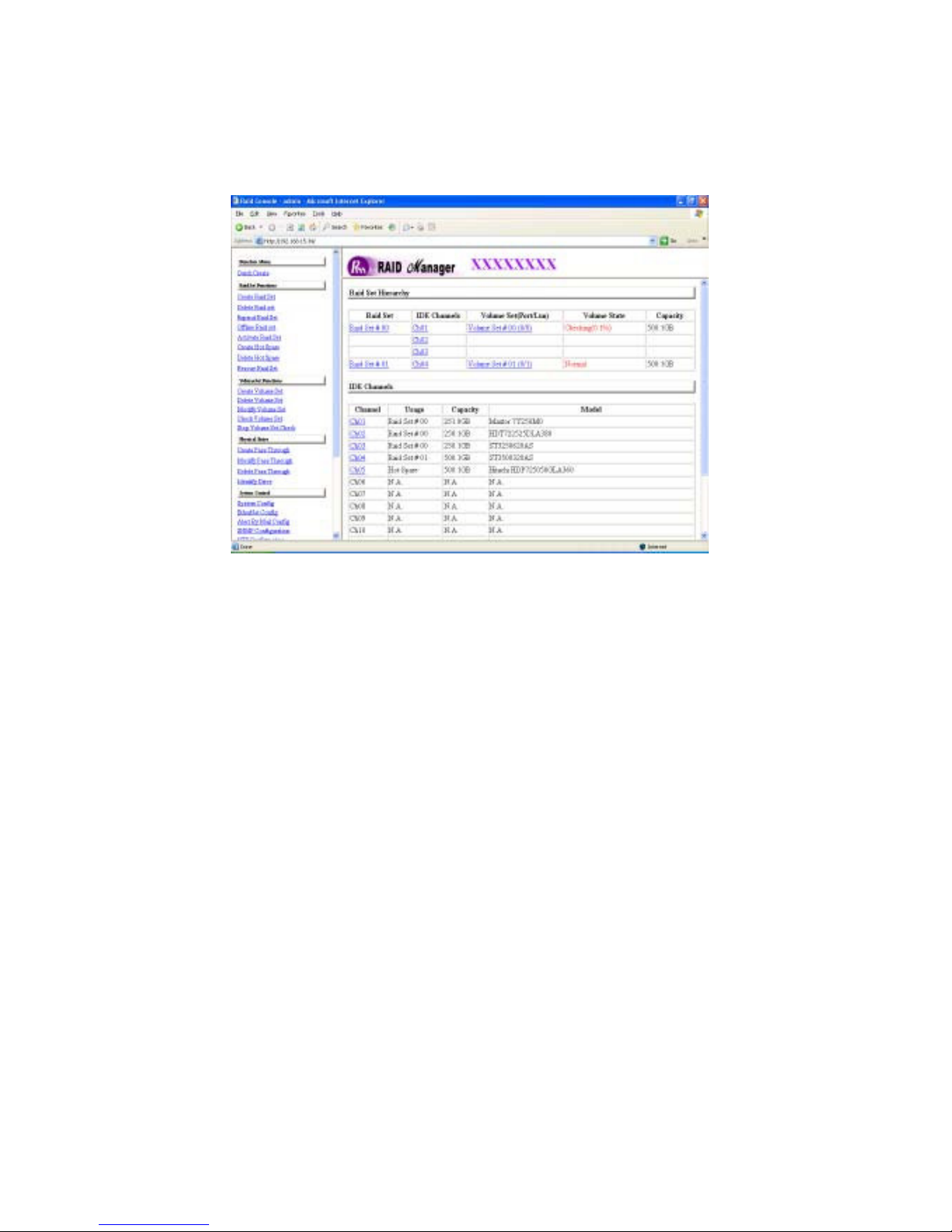
3.7.6 Stop Volume Set Check
Use this option to stop the Check Volume Set function.
Page 69
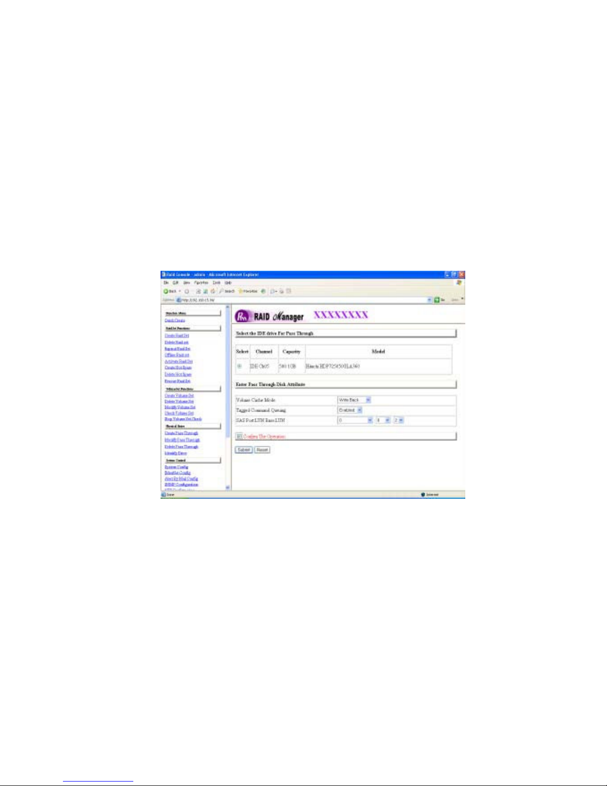
3.8 Physical Drive
Choose this option from the Main Menu to select a physical disk and to perform the operations listed below.
3.8.1 Create Pass-Through Disk
To create pass-through disk, go to the main menu and click on the Create
Pass-Through link. The relative setting function screen appears.
Disk is now not controlled by the internal RAID subsystem firmware and thus
cannot be a part of a volume set. The disk is available to the operating system
as an individual disk. It is typically used in a RAID system where the operating
system is on it and disk is desired to be not controlled by the RAID system’s
firmware. User can also select the cache mode, Tagged Command Queuing
and SAS Port/LUN Base/LUN # on this volume.
Page 70
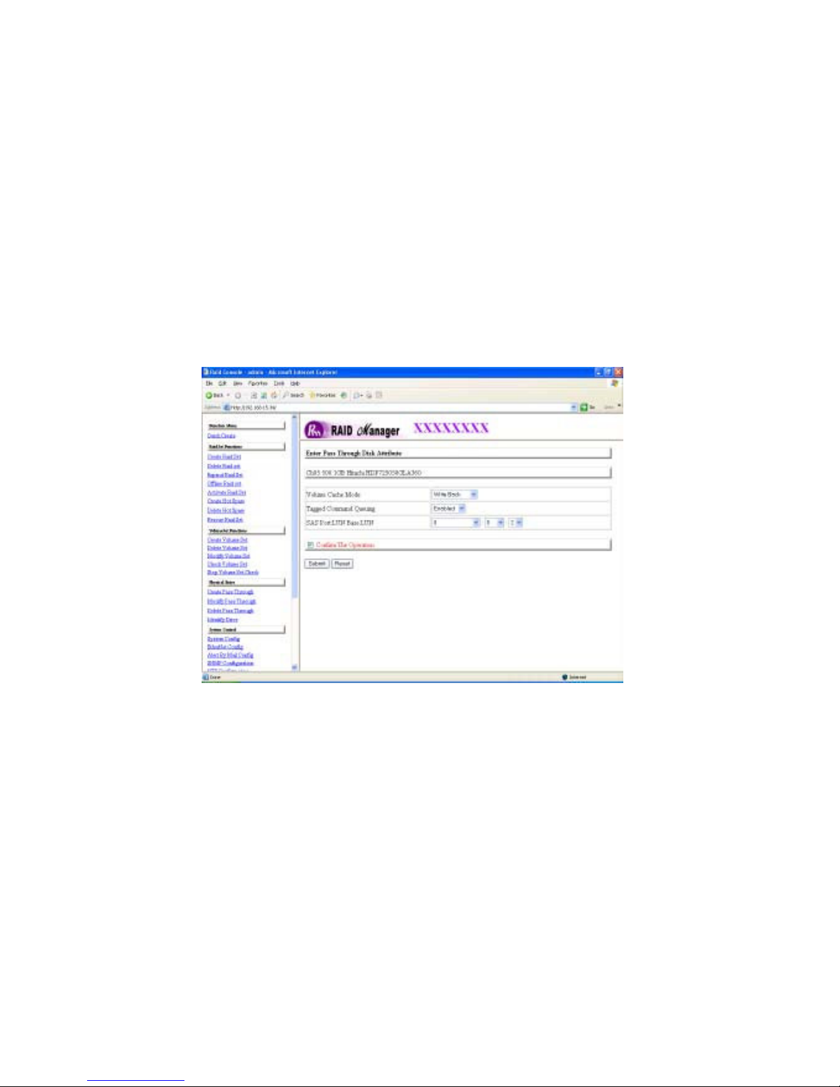
3.8.2 Modify Pass-Through Disk
Use this option to modify the Pass-Through Disk Attribute. User can modify the
cache mode, Tagged Command Queuing and SAS Port/LUN Base/LUN on an
existed pass through disk.
To modify the pass-through drive attribute from the pass-through drive pool,
move the cursor to and click on the Modify Pass-Through link. The Select
“The Pass Through Disk For Modification” screen appears, S el e ct the
Pass-Through Disk from the pass-through drive pool and click on the Submit
button to select drive.
The “ Enter Pass-Through Disk Attribute” screen appears, modify the drive
attribute values to your desired setting.
Page 71
3.8.3 Delete Pass-Through Disk
To delete pass-through drive from the pass-through drive pool, move the
mouse cursor bar to the main menus and click on Delete Pass Through link.
After you complete the selection, Check the Confirm the Operation and
click on the Submit button to complete the delete action.
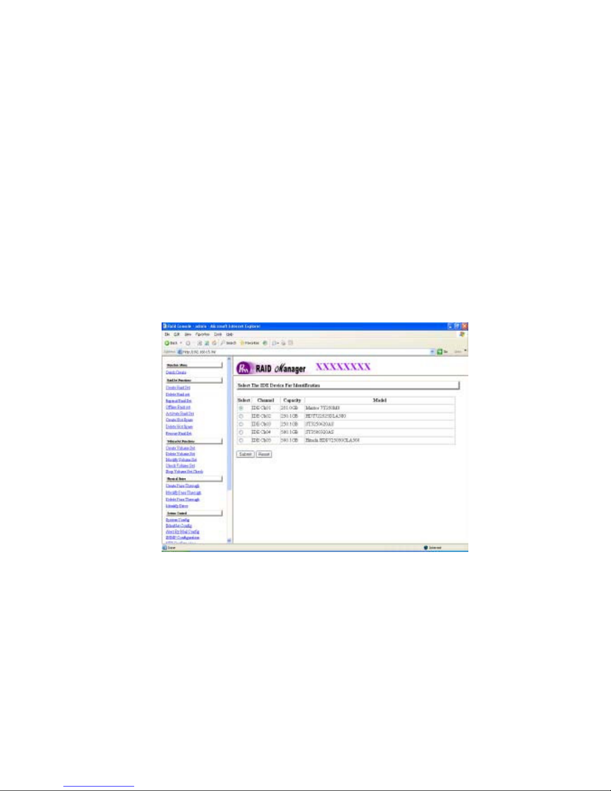
3.8.4 Identify Selected Drive
To prevent removing the wrong drive, the selected disk LED will light for
physically locating the selected disk when the Identify Selected Drive is
selected.
To identify the selected drive from the drives pool, move the cursor to and click
on Identify Selected Drive link. The “Select the IDE Device For
identification” screen appears, Select the IDE device from the drives pool to be
identified. After completing the selection, click on the Submit button to identify
selected drive. Drive slot led will flash to identify disk drive.
Page 72
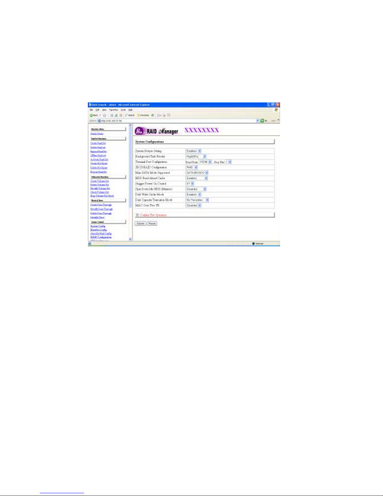
3.9 System Configuration
3.9.1 System Configuration
To set the raid system function, move the cursor bar to the main menu and
click on he Raid System Function link. The Raid System Function menu will
show all items. Select the desired function.
System Beeper Setting:
The Alert Beeper function item is used to Disabled or Enable the RAID subsystem controller alarm tone generator.
RAID Rebuild Priority:
The Raid Rebuild Priority is a relative indication of how much time the controller
devotes to a rebuild operation. The RAID subsystem allows user to choose the
rebuild priority (Ultra Low, Low, Medium, High) to balance volume set access
and rebuild tasks appropriately. For high array performance, specify a Low
value.
Page 73

Terminal Port Configuration:
Speed setting values are 1200, 2400, 4800, 9600, 19200, 38400, 57600, and
115200.
Stop Bits values are 1 bit and 2 bits.
Note: Parity value is fixed at None.
Data Bits value is fixed at 8 bits.
JBOD/RAID Configuration
The RAID subsystem supports JBOD and RAID configuration.
Maximum SATA Mode Supported:
The 16 SATA drive channel can support up to SATA ll, which runs up to 300MB/s.
NCQ is a command protocol in Serial ATA that can only be implemented on native
Serial ATA hard drives. It allows multiple commands to be outstanding within a
drive at the same time. Drives that support NCQ have an internal queue where
outstanding commands can be dynamically rescheduled or re-ordered, along with
the necessary tracking mechanisms for outstanding and completed portions of
the workload. RAID subsystem allows user to choose the SATA Mode: SATA150,
SAT150+NCQ, SAT300, SATA300+NCQ.
HDD Read-Ahead Cache:
This option allows the users to disable the cache of the HDDs on the RAID
subsystem. To some HDD models, disabling the cache in the HDD is
necessary to prove the RAID subsystem functions correctly.
Stagger Power-On Control:
This option allows the power supplier to power up in order each HDD on the
RAID subsystem. In the past, all the HDDs on the RAID subsystem are
powered up altogether at the same time. The power transfer time (lag time)
from the last HDD to the next one can be set within the range of 0.4 to 6.0.
Page 74

Spin Down Idle HDD (Minutes):
This option is to spin down hard drives after they have been idle for a selectable amount of time. The setting values are Disabled, 1(For Testing), 3, 5, 10, 15,
20, 30, 40, 50, and 60.
Disk Write Cache Mode:
The RAID subsystem supports auto, enabled and disabled. When the RAID subsystem with BBM (battery backup module) the auto option will be Enabled disk
write cache. Otherwise, the auto option will be Disable disk write cache.
Disk Capacity Truncation Mode:
This RAID subsystem use drive truncation so that drives from differing vendors
are more likely to be able to be used as spares for each other. Drive truncation
slightly decreases the usable capacity of a drive that is used in redundant
units.
Multiples Of 10G: If you have 120 GB drives from different vendors; chances
are that the capacity varies slightly. For example, one drive might be 123.5 GB,
and the other 120 GB. This drive Truncation mode Multiples of 10G uses the
same capacity for both of these drives so that one could replace the other.
Multiples Of 1G: If you have 123 GB drives from different vendors; chances
are that the capacity varies slightly. For example, one drive might be 123.5 GB,
and the other 123.4 GB. This drive Truncation mode Multiples of 1G uses the
same capacity for both of these drives so that one could replace the other.
No Truncation: RAID system performs no truncation to the disk capacity.
MAC Over Two TB:
Use this option to enable volume size over 2TB in MAC O/S.
Page 75
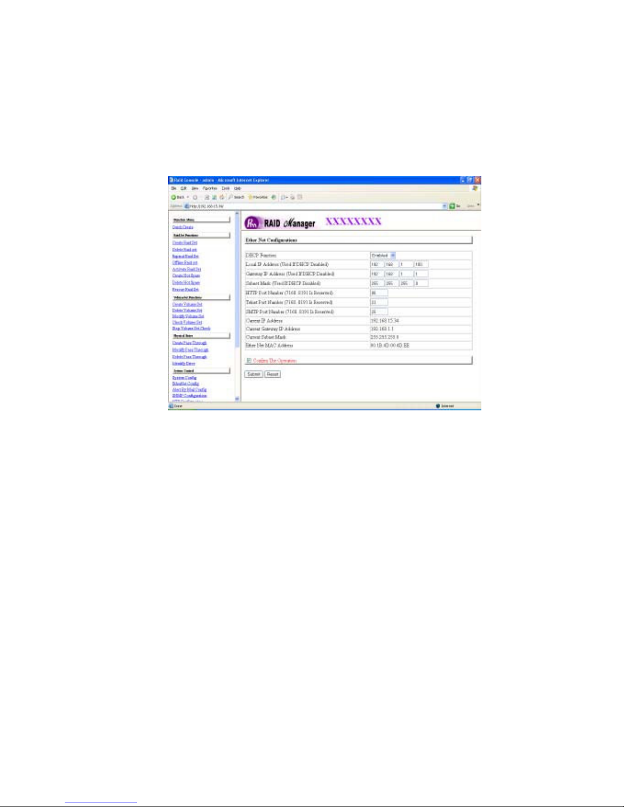
3.9.2 EtherNet Config
To set the EtherNet function, go to the main menu and click on the EtherNet
Config link. The Raid System EtherNet Function menu will show all items.
Select the desired setting, check the “Confirm the Operation” and then click the
Submit button.
Page 76
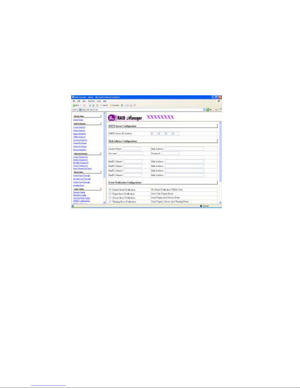
3.9.3 Alert by Mail Config
To set the Event Notification function, go to the main menu and click on the Alert
by Mail Config link. The Raid System Event Notification Function menu will show
all items. Select the desired setting, check the “Confirm the Operation” and then
click the Submit button. When an abnormal condition occurs, an error message
will be emailed to the administrator that a problem has occurred. Events are
classified to 4 levels (urgent, serious, warning, message).
Page 77
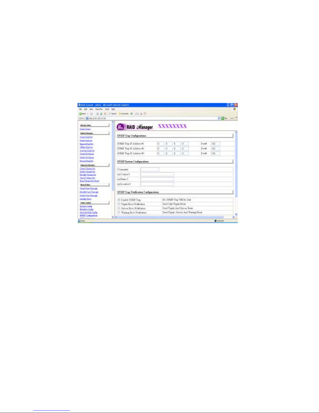
3.9.4 SNMP Configuration
The SNMP gives users independence from the proprietary network management
schemes of some manufacturers and SNMP is supported by many WAN and LAN
manufacturers enabling true LAN/ WAN management integration.
To set the SNMP function, go to the main menu and click on he SNMP
Configuration link. The “Raid System SNMP Function” menu will show all
items. Select the desired setting.
SNMP Trap Configurations: Type the SNMP Trap IP Address. The Port default is 162.
SNMP System Configuration:
Community: The default is Public.
(1) sys Contact.0; (2 )sys Location.0; (3) sys Name.0: SNMP parameter (31
bytes max). If this 3 categories are selected during initial setting then
when an error occurs SNMP will send out a message that includes the 3
categories within the message. This allows user to easily define which
RAID unit is having problem. Once this setting is done, alert by mail
configuration will also work in the same way.
Page 78
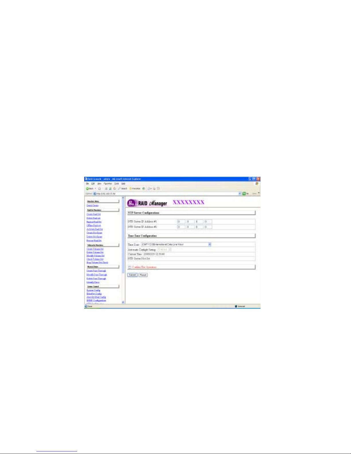
SNMP Trap Notification Configurations: Select the desired function.
After you complete the addition, Check the Confirm the Operation and click
on the Submit button to complete the action.
3.9.5 NTP Configuration
NTP stands for Network Time Protocol, and it is an Internet protocol used to
synchronize the clocks of computers to some time reference. NTP is an Internet
standard protocol. You can directly type your NTP Server IP Address to have
the RAID subsystem can work with it.
To set the NTP function, g o to the main menu and click on the NTP
Configuration link. The Raid System NTP Function menu will show all items.
Select the desired setting, check the “Confirm the Operation” and then click the
Submit button.
.
Page 79
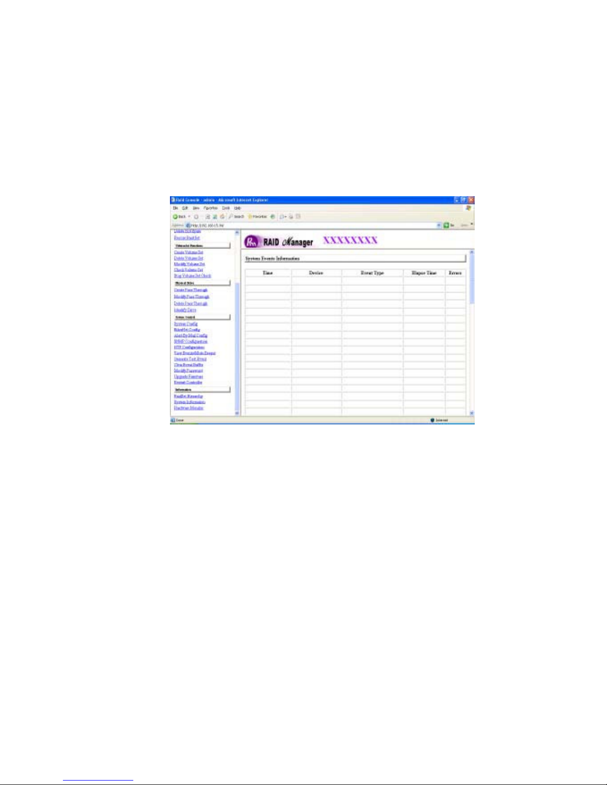
3.9.6 View Events
To view the RAID subsystem controller’s information, go to the main menu and
click on the System Information link. The “Raid Subsystem events
Information” screen appears.
Choose this option to view the system events information: Time, Device, Event
type, Elapse Time and Errors are displayed. The RAID system does not built
the real time clock. The Time information is the relative time from the RAID
subsystem power on.
Page 80
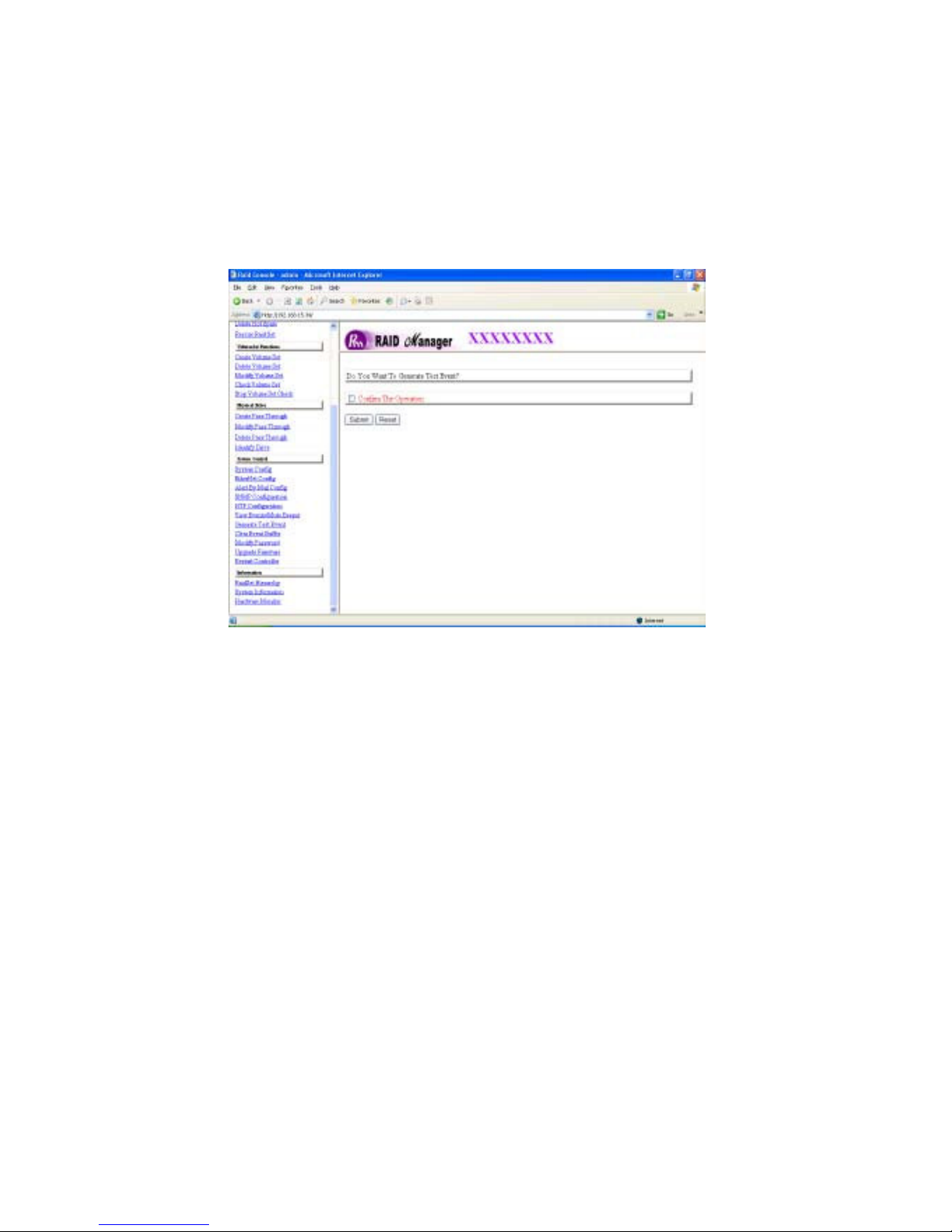
3.9.7 Generate Test Events
If you want to generate test events, go to the main menu and click on he
Generate Test Events link. Check the Confirm the Operation, and click on
the Submit button in the screen to create the hot spares. Then click
View Events/Mute Beeper link to view the test event.
on the
Page 81
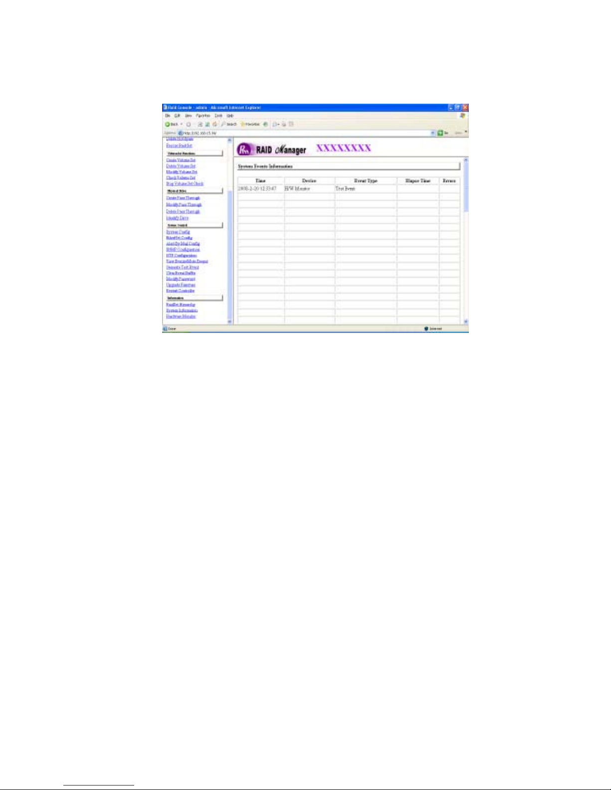
3.9.8 Clear Events Buffer
Use this feature to clear the entire events buffer information.
3.9.9 Modify Password
To set or change the RAID subsystem password, go to the main menu and click on
the Modify Password link. The “Modify System Password” screen appears.
Page 82
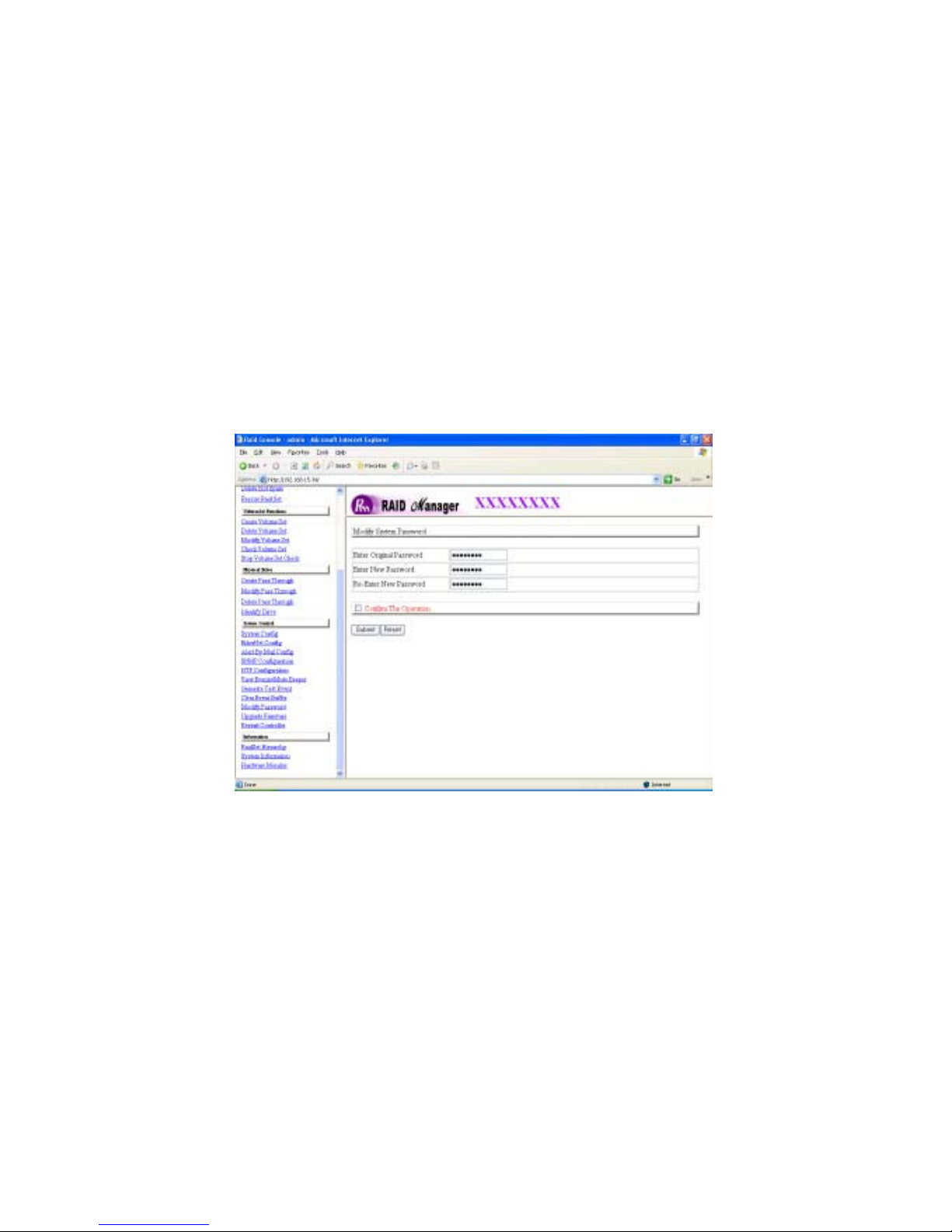
The password option allows user to set or clear the raid subsystem’s
password protection feature. Once the password has been set, the user can
only monitor and configure the raid subsystem by providing the correct password.
The password is used to protect the internal RAID subsystem from
unauthorized entry. The controller will check the password only when
entering the Main menu from the initial screen. The RAID subsystem will
automatically go back to the initial screen when it does not receive any
command in ten seconds.
To disable the password, press the Enter key only in both the Enter New
Password and Re-Enter New Password column. Once the user confirms
the operation and clicks the Submit button. The existing password will be
cleared. No password checking will occur when entering the main menu from
the starting screen. If a password is lost please contact Partners data Systems
to reset your password to default.
3.9.10 Upgrade Firmware
Please reference the section 4.2 for more information.
Page 83
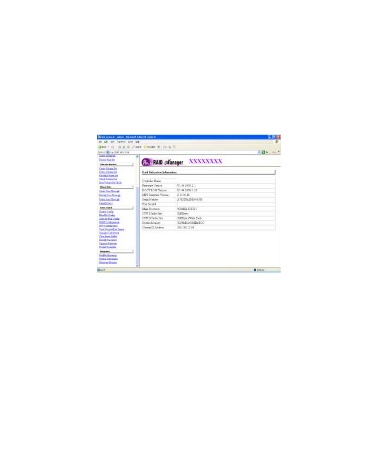
3.10 Information Menu
3.10.1 Raid Set Hierarchy
Use this feature to view the internal raid subsystem current raid set, current
volume set and physical disk configuration.
3.10.2 System Information
To view the RAID subsystem controller’s information, go to the main menu and
click on the System Information link. The “Raid Subsystem Information”
screen appears.
Use this feature to view the raid subsystem controller’s information. The controller
name, firmware version, serial number, main processor, CPU data/Instruction
cache size and system memory size/speed appear in this screen.
Page 84
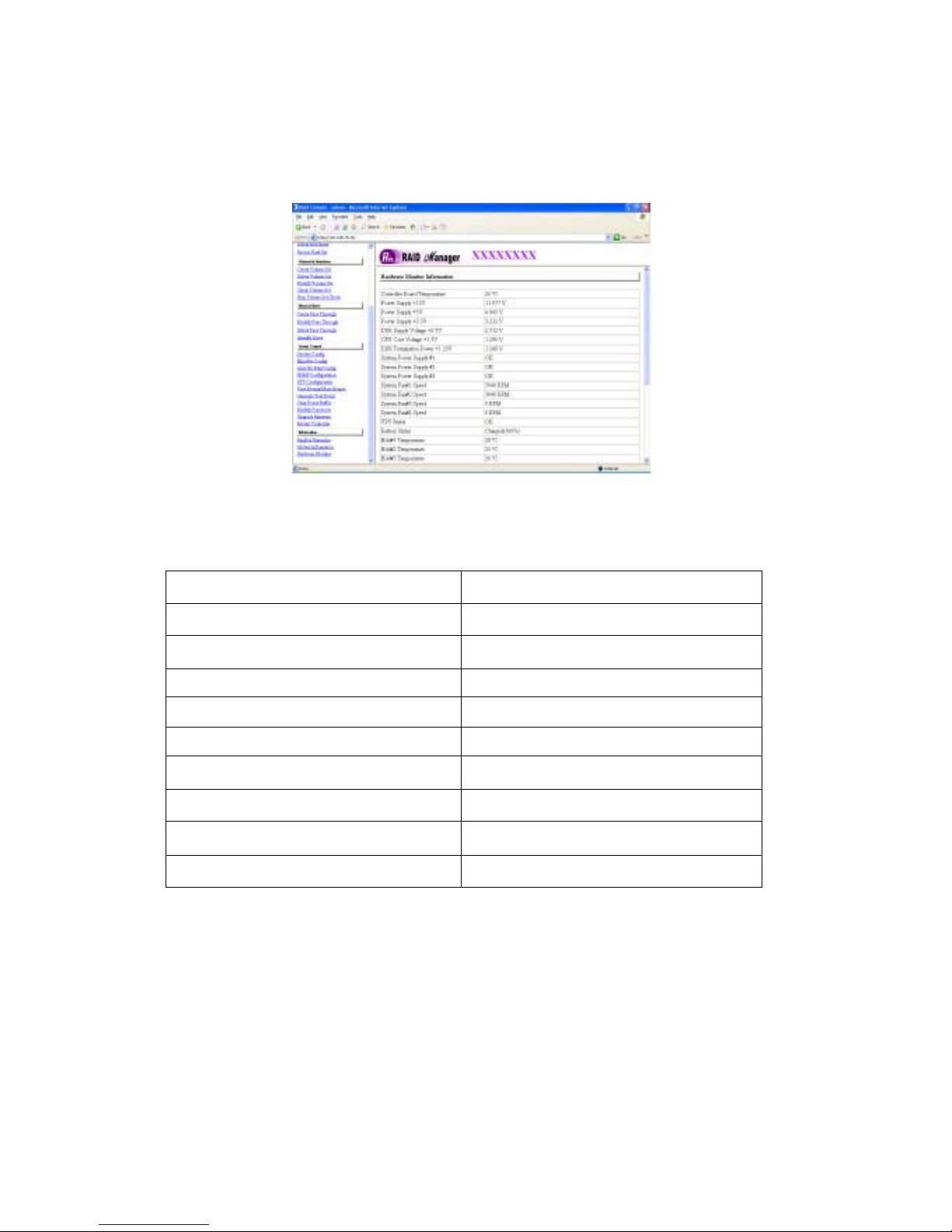
3.10.3 Hardware Monitor
To view the RAID subsystem controller’s hardware monitor information, go to the
main menu and click the Hardware Monitor link. The “Hardware Information”
screen appears.
The Hardware Monitor Information provides the temperature, fan speed (chassis
fan) and voltage of the internal RAID subsystem. All items are also unchangeable.
The warning messages will indicate through the LCD, LED and alarm buzzer.
Item
Warning Condition
Controller Board Temperature
HDD Temperature
Controller Fan Speed
Power Supply +12V
Power Supply +5V
Power Supply +3.3V
DDR Supply Voltage +2.5V
CPU Core Voltage +1.3V
DDR Termination Power +1.25V
> 60 Celsius
> 55 Celsius
< 1500 RPM
< 10.5V or > 13.5V
< 4.7V or > 5.4V
< 3.0V or > 3.6V
< 2.25V or > 2.75V
< 1.17V or > 1.43V
< 1.125V or > 1.375V
Page 85
3.11 Creating a New RAID or Reconfiguring an Existing
RAID
You can configure raid sets and volume sets using Quick Create or Raid Set
Functions/Volume Set Functions configuration method. Each configuration
method requires a different level of user input. The general flow of operations
for raid set and volume set configuration is:
Step
1
2
3
4
5
Action
Designate hot spares/pass-through (optional).
Choose a configuration method.
Create raid set using the available physical drives.
Define volume set using the space in the raid set.
Initialize the volume set and serve volume set to the HOST OS.
Page 86

Chapter 4
Array Maintenance
This chapter describes more information about your Disk Array. The
following items are described in detail.
• Updating Firmware
• Hot Swap Components
4.1 Upgrading the Firmware
Upgrading Flash Firmware Programming Utility
Since the RAID subsystem controller features flash firmware, it is not necessary to
change the hardware flash chip in order to upgrade the RAID firmware. The
user can simply re-program the old firmware through the RS-232 port or Web
GUI interfaces. New releases of the firmware are available in the form of a DOS
file and can be downloaded from the Partners Data Systems support webpage. The
file available at the support webpage .zip file that contains the following:
• XXXXVVV.bin Firmware Binary and the XXXXVVV-boot.bin (where
“XXXX” refers to the model name and “VVV” refers to the firmware version)
• README.TXT that contains the history information of the firmware
changes and important firmware notes. Read this file first before upgrading
the firmware.
These files must be extracted from the compressed file and copied to one
directory in drive A or C. The boot.bin file must be installed first before
the .bin file is installed. See the Readme.txt file for important notes
regarding the upgrade.
Establishing the Connection for the RS-232
The firmware can be downloaded to the RAID subsystem controller by using an
ANSI/VT-100 compatible terminal emulation program or Remote web browser
management. You must complete the appropriate installation procedure before
proceeding with this firmware upgrade. Whichever terminal emulation program
is used must support the ZMODEM file transfer protocol.
Page 87
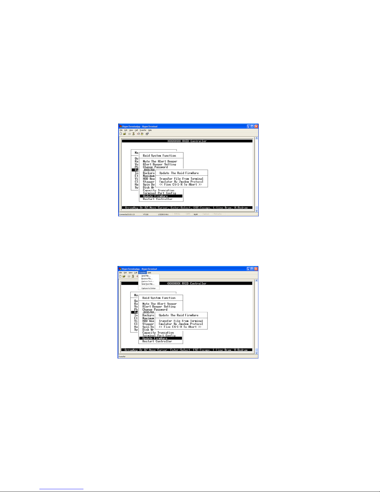
4.1.1 Upgrading Firmware through ANSI/VT-100 Terminal Emulation
1. From the Main Menu, scroll down to Raid System Function and press Enter
key.
2. Choose the Update Firmware and press Enter key.. The “Update the Raid
Firmware dialog box appears. You then have 20secs to start the firmware
upload or the RAID system will time out the operation. If so, start over again with
selecting Upgrade Firmware.
3. Go to the terminal emulator tool bar and select Transfer and click on “Send
File”.
Page 88
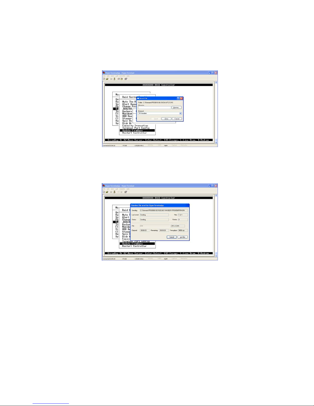
4. Select ZMODEM modem under Protocol. ZMODEM as the file transfer protocol
of your terminal emulation software.
5. Click the Browse button and browse to the location where the firmware files
are located. Select the XXXXVVV-boot.bin file first.
6. Click Send button and upload should start. If not start procedure over again.
Page 89
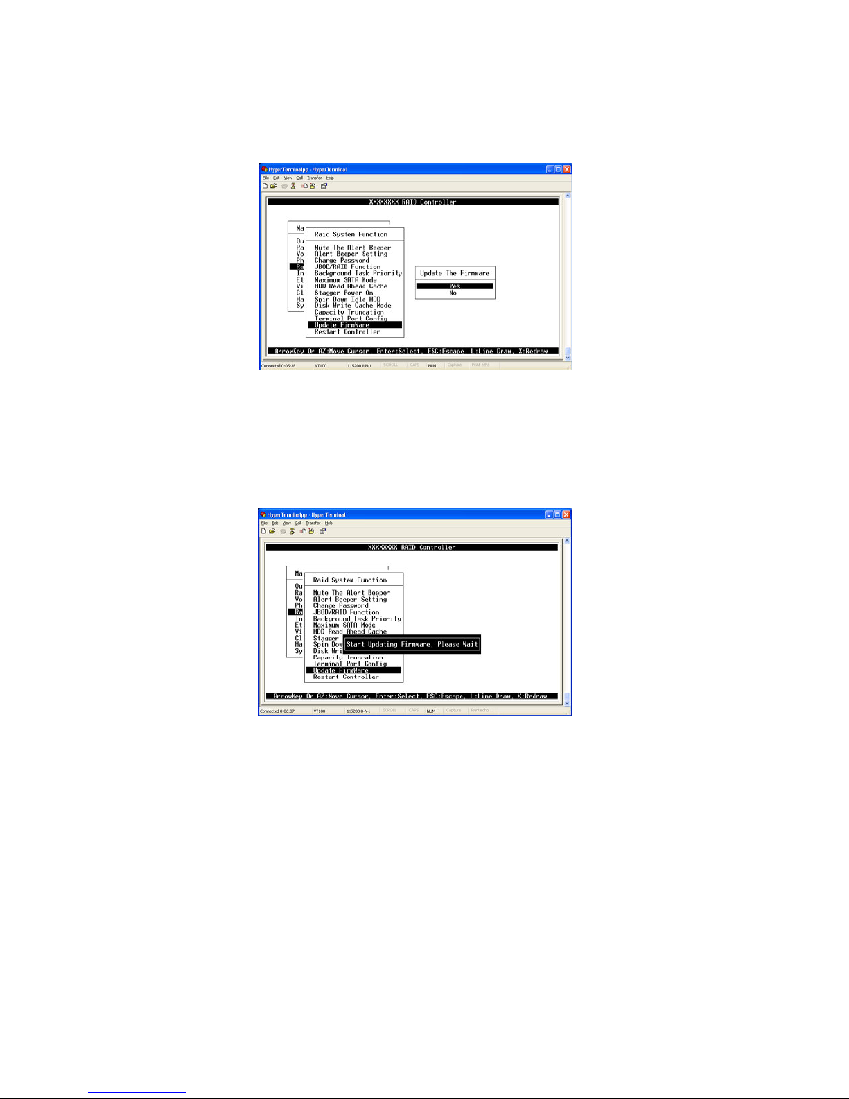
7. When the firmware completes downloading, the confirmation screen appears.
Select Yes and press Enter key to start programming of the flash ROM.
8. Flash programming starts and will display “Start Updating
Firmware, Please Wait”.
Page 90
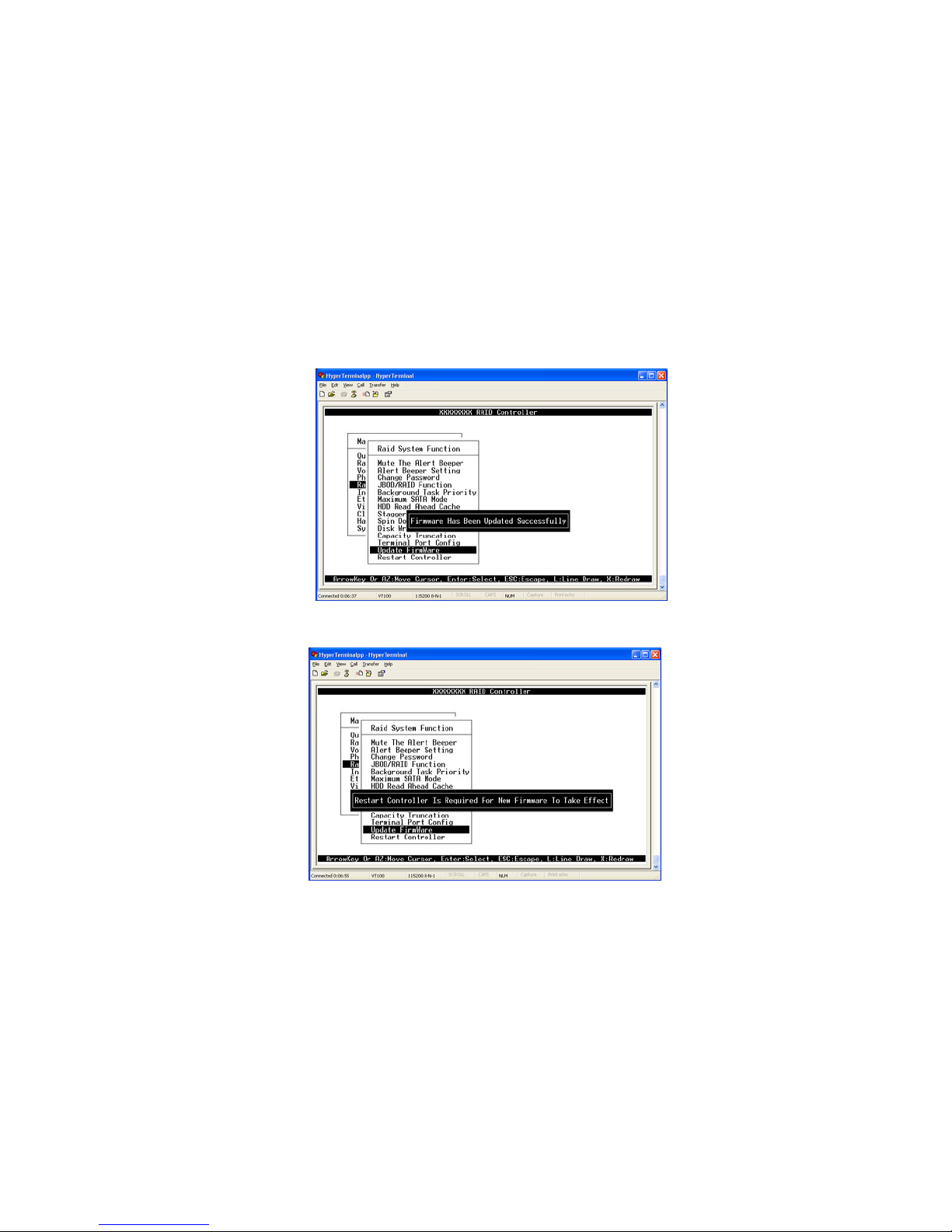
9. The boot.bin file will take approximately 3-5 seconds to complete.
10. After the firmware upgrade is complete, “Firmware
Has Been Updated Successfully” will be displayed.
11.) Repeat upgrade steps again for the 2nd firmware file XXXXVVV.bin. This file
will talk about 30 seconds load. Wait for the message
“Firmware
Has Been
Updated Successfully” to be displayed and then press Enter key. The
“Restart Controller is Required for new Firmware to Take effect” message
will appear. Next, either power cycle RAID system or select Restart Controller.
After the RAID system finish rebooting the upgrade is complete. Go to the
System Information screen to verify upgrade is complete.
Page 91
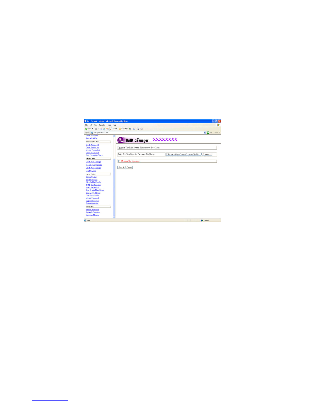
4.1.2 Upgrading Firmware through the Web Browser Management
1. To upgrade the RAID subsystem firmware, go to the main menu and click on the
Upgrade Firmware link. The “Upgrade the Raid System Firmware” screen
appears.
2. Click the Browse button and browse to the location where the firmware files
are located. Select the XXXXVVV-boot.bin file first.
3. Click the Confirm the Operation and press the Submit button.
4. The Web Browser begins to download the firmware binary to the controller
and start to update the flash ROM.
The boot.bin file will take approximately 3-5
seconds to complete.
Page 92
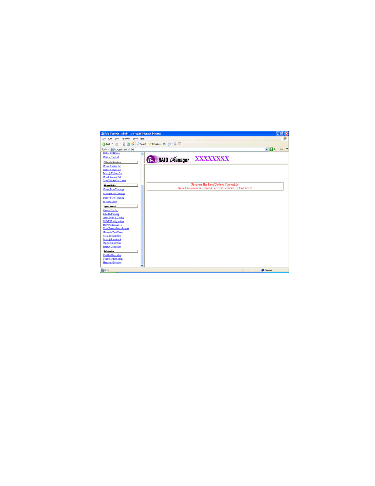
5. After the firmware upgrade is complete, the web GUI will display “Firmware
Has Been Updated Successfully”.
6. Repeat the upgrade steps again for the 2nd firmware file XXXXVVV.bin. This
file will talk about 30 seconds load. Wait for the message
“Firmware
Has Been
Updated Successfully, Restart Controller is required for new Firmware to
Take effect” message will appear. Next, either power cycle RAID system or
select Restart Controller. After the RAID system finish rebooting the upgrade is
complete. Go to the System Information screen to verify upgrade is complete.
Page 93
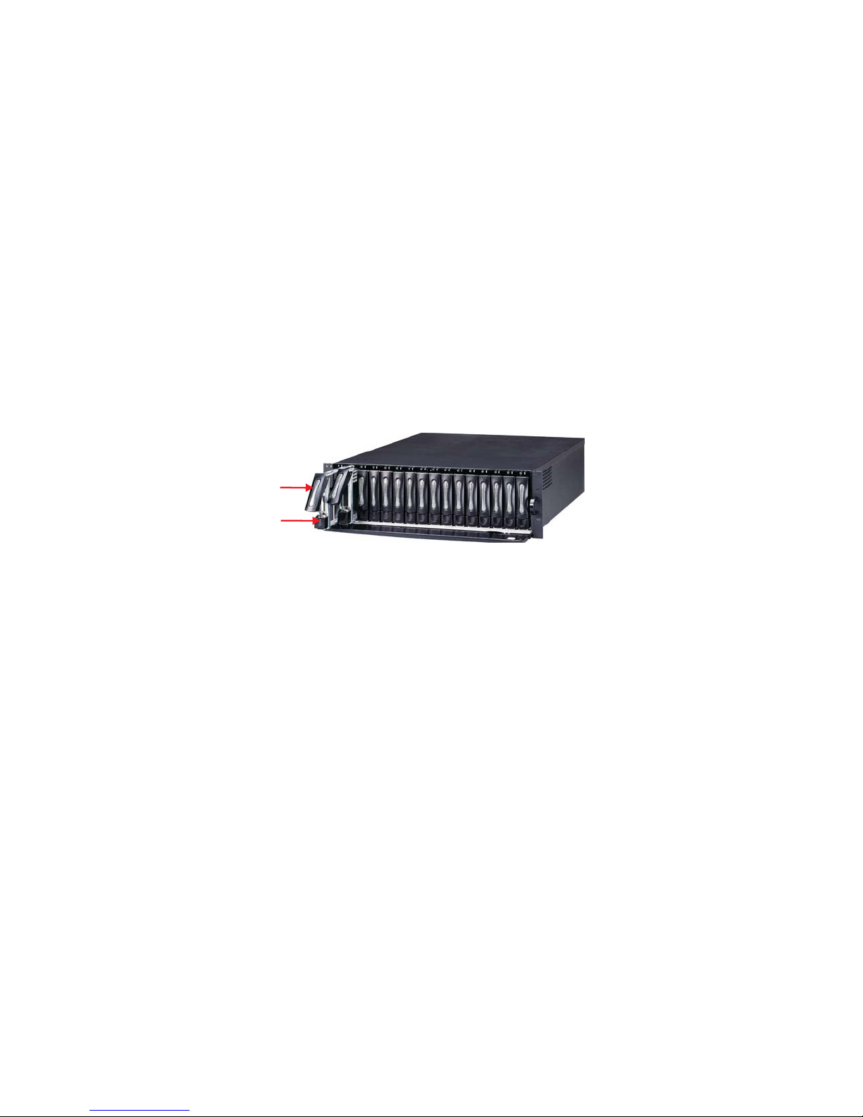
4.2 Hot Swap Components
The disk array supports hot-swappable disk trays, power supply modules and
cooling fan unit. The following sections describe how to remove and install the
“Hot-Swap” parts without interrupting the data access while the disk array is on.
4.2.1 Replacing a disk
To replace a disk, perform the following steps (Refer to 2.5 Installing hard
disks)
1. Open the tray lever by sliding the latch and wait for the drive
to spin down. The disk LED on the front panel will turn from green to
red indicating the disk is powered down.
2. Lift the lever to disengage the disk tray from the slot.
3. Gently pull the disk tray out of the slot.
4. Replace the HDD.
5. Slide the tray into a slot until it clicks into place. The HDD status LED will
turn green on front panel.
6. Press the lever in until you hear the latch click into place.
Page 94
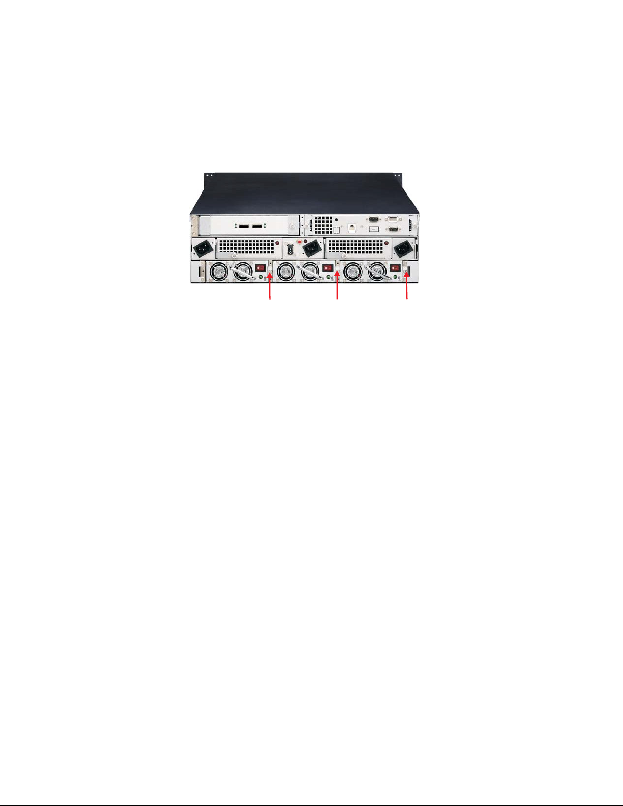
4.2.2 Replacing a Power Supply
1. Remove the screws located at the corners of the power supply. Place
the screws in a safe place as you will need them later when you install a
new power supply.
2. Use the handle to pull out the defective power supply.
3. Replace it with a 300W power supply.
4. Slide the new power supply in until it clicks into place.
5. Replace the screws you removed in step 1.
6. When you replace a new power supply unit, you should then push the
power supply reset switch to stop the buzzer alarm. The new power supply unit
will link with the other unit immediately and will start working after you press
the power supply reset switch, and the buzzer warning noise will stop.
Page 95
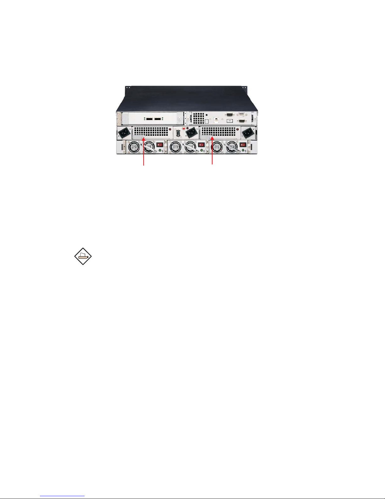
4.2.3 Replacing a Fan
1. Unscrew the fan holder.
2. Disconnect the fan cable connects between the backplane and the fan.
3. The fans are attached to the fan holder. Remove the screws on the
corners of the defective fan. Place the screws on a safe place as you
will need them later when you install a new fan.
Note:
We r ecomm end t hat you rem ov e the fan ho ld er from th e
subsystem. This allows easy installation and unlimited workspace
when replacing the fan.
4. Install a new fan using the screws you removed in step 3.
5. Replace the fan holder.
6. Reconnect the fan cable connects.
Page 96
Appendix A
Technical Specification
RAID processor
RAID level
Cache memory
No. of channels (host+disk)
Host bus interface
Data transfer
Back Plane Board
Hot swap disk bays
Hot swap power supply
Cooling fan
On-line expansion
Multiple RAID selection
Failed disk auto rebuild
Array Roaming
Bad block auto-remapping
Intel 80321 RISC 64-bit
0, 1, 3, 5, 6, 0+1 and JBOD
Up to 1024MB DDR SDRAM ECC
Un-buffered
2+16
Two 4x mini SAS (3Gb/s) ports
Up to 300MB/sec per channel
SATA II
16
3
2 (blower)
Yes
Yes
Yes
Yes
Yes
End
Online RAID level migration
Audible alarm
Host Independent
Failed drive indicators
Yes
Yes
Yes
Yes
 Loading...