

Page 1
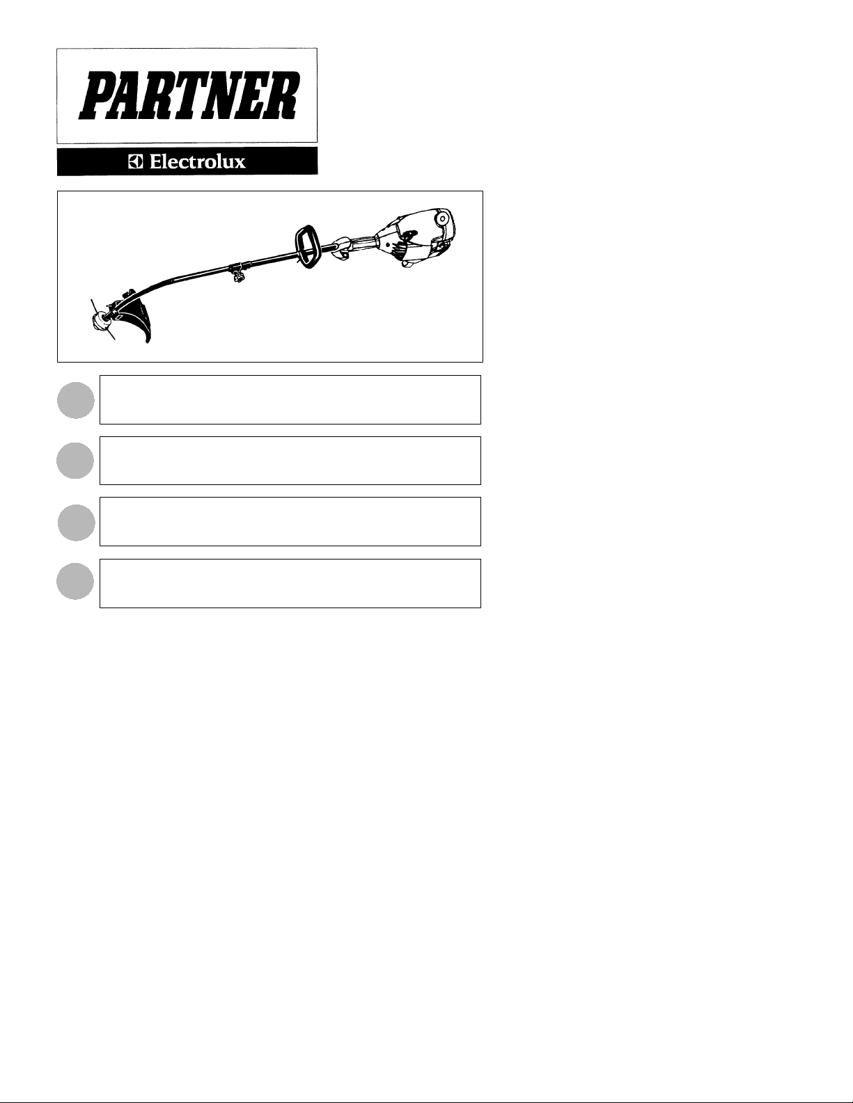
T280
INSTRUCTION MANUAL
IMPORT ANT INFORMATION
GB
sure you understand them before using this unit. Retain these instructions for future
reference.
: Please read these instructions carefully and make
MANUEL D’INSTRUCTIONS
RENSEIGNEMENTSIMPORTANTS:
FR
atentivement les instructions et assurez--vous de les avoir comprises. Conservez
les instructions pour référence ultérieure.
Avant d’utilisercet ap pareil, veu illez lire
BETRIEBSANWEISUNG
WICHTIGE INFORMA TION:
DE
Geräts aufmerksam durch. Verwenden Sie es erst, wenn Sie sicher sind, daß Sie
alle Anweisungen verstanden haben und gut aufbewahren .
Lesen Sie diese Hinweise zur Handhabung des
MANUAL DE INSTRUCCIONES
INFORMACIÓN IMPORTANTE:
ES
asegúrese de entenderlas antes de utilizar esta aparato. Conservelas instrucciones para la referencia en el futuro.
Lea atentamente las instrucciones y
530164505 1/16/04
Page 2
Trimmer
Head
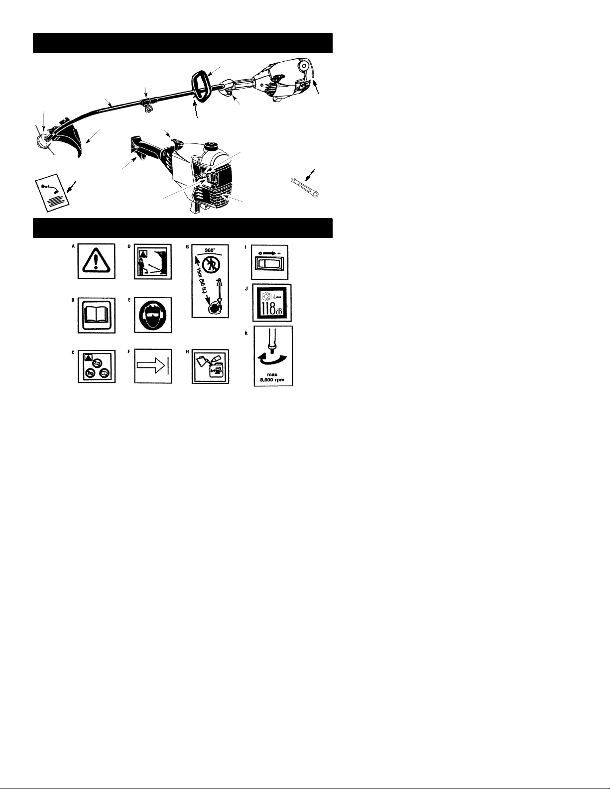
IDENTIFICATION (WHAT IS WHAT?)
Assist Handle
Coupler
Shaft
ON/OFF Switch
Primer Bulb
Manual
Shield
Throttle Trigger
Starter
Handle
Assist handle adjustment
Fuel tank
Wrench
Choke
Lever
Muffler
IDENTIFICATION OF SYMBOLS
A.
WARNING!
serious or even fatal injury.
B. Readandunderstandtheinstruction manual before using the trimmer.
C. Never use blades with this tool.
D.
WARNING!
injured. Always wear eye protection.
E. Always use:
Ear protection
Protective glasses or visor
F. Assist handle to be positioned only below the arrow.
G. Theoperator of the machine must insure that noonecomes within a 15 meterradius
while working.Whenseveral operatorsareworking withinthesame areaa safety dis-
tance of at least 15 meters must be observed.
H. Use unleaded or quality leaded petrol andtwo--stroke oil mixed at a ratio of 2.5%.
I. Engine ON/OFF Switch.
J. Sound power level
K. Max speed of output axle, rpm
Thistrimmercanbe dangerous!Careless or improperusecan cause
The trimmer line can throw objects violently. You can be blinded or
2
Page 3
SAFETY RULES
WARNING:
appliances, basic safety precautions should always be followed to reduce the risk of fire and
serious injury. Read andfollow all instructio ns.
This power unit can be dangerous! Operator is
responsible for following instructions andwarnings on unit and in manual. Read entire instruction manual before using unit! Be thoroughly familiarwiththecontrolsandthe properuse ofthe
unit. Restrict the use of this unit to persons who
read, understand, and follow instructions and
warnings on unit and in manual. Never allow
children to operate this unit.
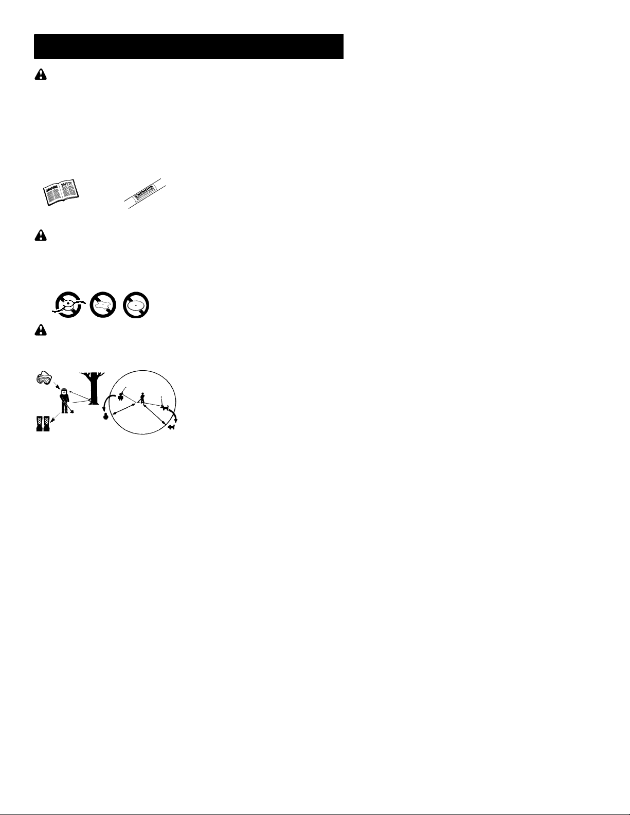
INSTRUCTION
MANUAL
DANGER:
trimmer attachment. Never use flailing devices with any attachment. This unit (when
usedwithsuppliedlinetrimmer attachment)is
designedfor line trimmer useonly.Useofany
other accessories with line trimmer attachmentwill increase the risk of injury.
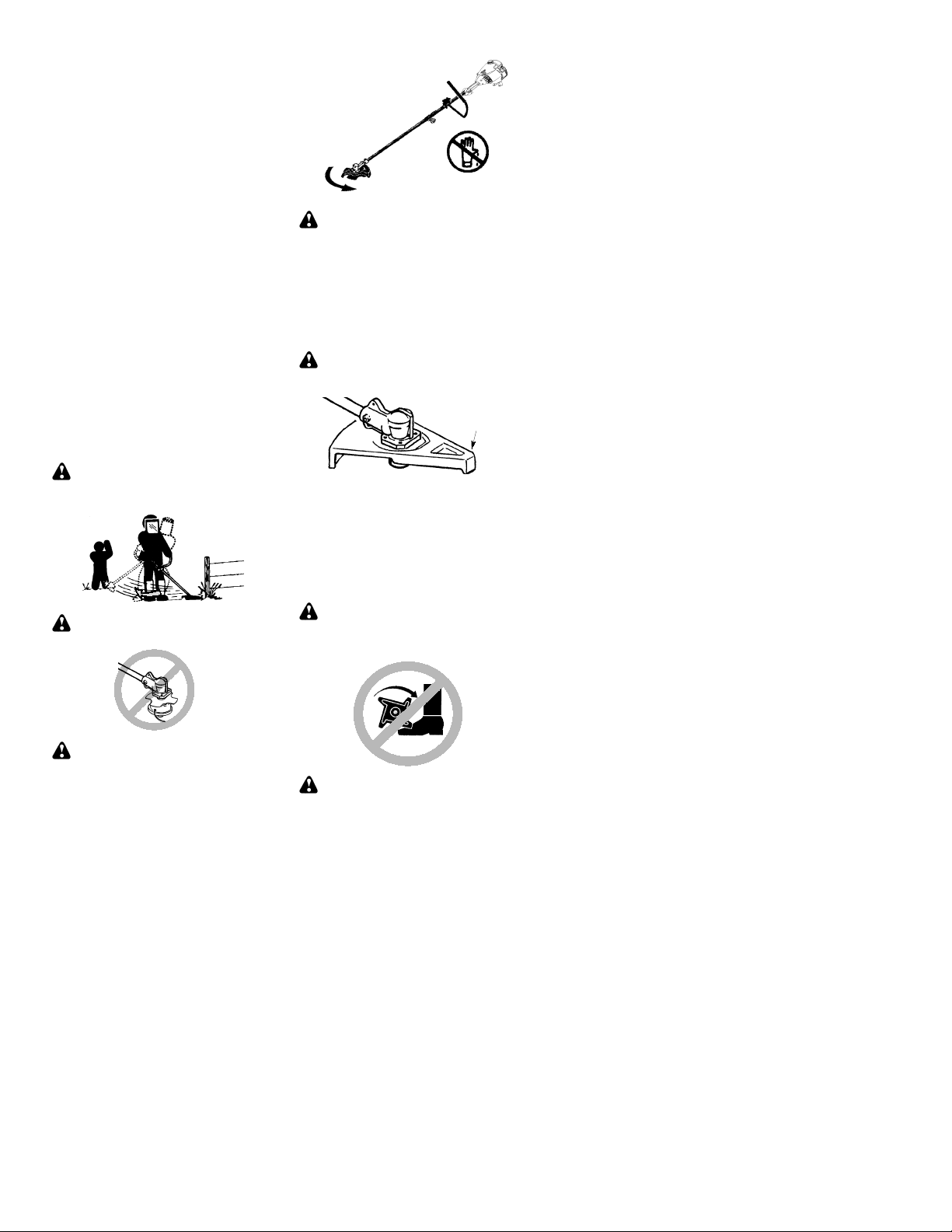
WARNING:
jects violently.Youand otherscan beblinded/
injured. Wear safety glasses and leg protection. Keep body parts clear of rotating line.
Safety Glasses or similar eye protection
Boots
Keepchildren, bystanders, and animals 15 meters away. If approached stop unit immediately.
If situations occur which are not covered in
this manual, usecare andgoodjudgement.If
youneedassistance,contactyourauthorized
service dealer.
OPERATORSAFETY
S Dress properly. Always wear safety
glasses or similar eyeprotection when operating, or performing maintenance, on
your unit (safety glasses are available).
Eye protection should be marked Z87.
S Always wear faceordust mask if operation
is dusty.
When using gardening
SAFETY INFORMATION
ON THE UNIT
Never use blades with line
Trimmer line throws ob-
Hazard Zone
15 meters
S Always wear heavy, long pants, long
sleeves, boots,andgloves. Wearingsafety
leg guards is recommended.
S Always wear foot protection. Do not go
barefoot or wear sandals. Stay clear of
spinning line.
S Securehair aboveshoulderlength. Secure
or remove loose clothing or clothing with
loosely hanging ties, straps, tassels, etc.
They can be caught in moving parts.
S Being fully covered also helps protect you
from debris and pieces of toxic plants
thrown by spinning line.
S Stay Alert. Do not operatethis unit when you
aretired,ill, upsetor und er theinflue nce ofalcoho l,drugs,or medicat ion. Watch wha tyou
are doing; use common sense.
S Wear hearing protection.
S Never start or run inside a closed room or
building. Breathing exhaust fumes can kill.
S Keep handles free of oil and fuel.
S Always keep engine on the right handside
of your body.
S Hold the unit firmly with both hands.
S Keep trimmer head (or other optional at-
tachment)belowwaistlevelandaway from
all parts of your body. Do not raise engine
above your waist.
S Keepall partsofyour body away from muf-
fler and spinning line (or other optional attachment). Keep engine below waist level.
A hot muffler can cause serious burns.
S Keepfirmfootingandbalance. Donotover-
reach or use from unstable surfaces such
as ladders, trees, steep slopes, rooftops,
etc.
S Use only in daylight or good artificial light.
S Use only for jobs explained in this manual
(or manuals for optional attachments).
UNIT / MAINTENANCESAFETY
S Disconnect the spark plug before performing
maintenance except carburetor adjustments.
S Look for and replace damaged or loose
parts before each use. Look for and repair
fuelleaksbeforeuse.Keepingoodworking
condition.
S Replace trimmer head parts that are
chipped, cracked, broken, or damaged in
any other way beforeusing the unit.
S Maintain unit according to recommended
procedures. Keep cutting line at proper
length.
S Use only 2mmdiameterPartner! brand line.
Neverusewire,rope, string,etc.
S Installrequiredshield properly beforeusing
the unit. Use only specified trimmer head;
make sure it is properly installed and securely fastened.
S Make sure unit is assembled correctly as
shown in this manual.
S Make carburetor adjustments with lower
endsupportedto preventlinefromcontacting any object.
3
Page 4
S Keepothers awaywhenmakingcarburetor
adjustments.
S Use only recommended Partner! acces-
sories andreplacement parts.
S Have all maintenance and service not ex-
plained in this manual performedby anauthorized service dealer.
FUEL SAFETY
S Mix and pour fuel outdoors.
S Keep away from sparks or flames.
S Use a container approvedforfuel.
S Donotsmoke or allow smoking nearfuelor
the unit.
S Avoidspillingfu el oroil. Wipeupall fuel spills.
S Move at least 3 meters away from fueling
site before starting engine.
S Stop engine and allow to cool before re-
moving fuel cap.
S Always store gasoline in a container ap-
proved for flammable liquids.
TRANSPORTINGAND STORAGE
S Allow theengineto cool; secure unit before
storing or transporting in vehicle.
S Emptyfueltankbefore storing ortransport-
ingtheunit.Useupfuel leftinthecarburetor
by starting engine and letting it run until it
stops.
S Storeunit and fuelinan areawherefuel va-
pors cannot reach sparks or open flames
from water heaters, electric motors or
switches, furnaces, etc.
S Storeunit so linelimiter cannotaccidentally
cause injury.Unitcanbe hungbythe shaft.
S Store the unit out of the reach of children.
SPECIAL NOTICE:
tions throughprolonged use of gasoline powered hand tools could cause blood vessel or
nerve damage in the fingers, hands, and
joints of people pronetocirculation disorders
or abnormal swellings. Prolongeduse in cold
weatherhasbeenlinked tobloodvesseldamagein otherwisehealthypeople. Ifsymptoms
occur such as numbness, pain, loss of
strength, change in skin color or texture, or
loss of feeling in the fingers, hands, orjoints,
discontinuetheuse ofthis toolandseekmedical attention. An anti-vibration system does
not guarantee the avoidance of these problems. Users who operate power tools on a
continual and regular basis must monitor
closely theirphysical conditionandthe condition of this tool.
Exposure to vibra-
LINE TRIMMERSAFETY
WARNING:
trimmed before each use. Remove objects
(rocks, broken glass, nails, wire, etc.) which
canbe thrownby orbecomeentangledinline.
Hard objects can damage the trimmer head
and be thrown causing serious injury.
S Use only for trimming, scalping, mowing and
sweeping. Do not use for edging, pruning or
hedge trimming.
S Cut from your right to your left. Cutting on
leftsideof theshield will throwdebrisaway
from the operator.
Inspect the area to be
ADDITIONAL SAFETY RULES
FOR OPTIONAL ATTACHMENTS
WARNING:
mentused,read entireinstruction manualbefore use andfollow all warnings and instructions in manual and on attachment.
WARNING:
installed when using edger or brushcutter attachments. Attachhandlebarabovearrowon
safetylabel onthe upper shaft(engineendof
unit). If your edger or brushcutterattachment
doesnot include ahandlebar,a handlebaraccessory kit (#530071451) is available from
your authorized service dealer.
EDGER SAFETY
WARNING:
edged before each use. Remove objects
(rocks, broken glass, nails, wire, etc.) which
can be thrown by the blade or can wrap
around the shaft.
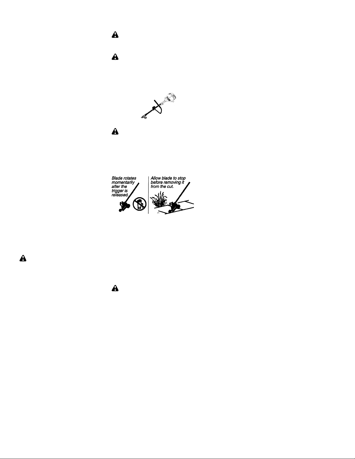
S Blade rotates momentarily after the trigger
is released. The blade can seriously cut
you or others.
S Allow blade to stop before removing it from
the cut.
S Throw away blades thatare bent, warped,
cracked, broken or damaged in any other
way. Replace parts that are cracked,
chipped, or damagedbeforeusing the unit.
S Do not attempt to remove cut material nor
hold material to be cut when the engine is
running or when cutting blade is moving.
S Always keepthe wheeland depthadjusting
skid in contact with the ground.
S Always push the unit slowly over the
ground. Stay alert for uneven sidewalks,
holes in the terrain, large roots, etc.
S Always use thehandlebarwhenusingedg-
er attachment.
BLOWER/VACUUMSAFETY
WARNING:
ing unit. Remove all debris and hard objects
such as rocks, glass, wire,etc.that can ricochet, be thrown, or otherwise cause injury or
damage during operation.
4
Foreach optional attach-
Ensure handlebar is
Handlebar
Inspect the area to be
Inspectareabeforestart-
Page 5
S Do not set unit on any surface except a
clean, hard area while engine is running.
Debris such as gravel, sand, dust, grass,
etc., could be picked up by the air intake
andthrownout throughdischarge opening,
damagingunit, property,or causingserious
injury tobystanders or operator.
S Never place objects inside the blower
tubes, vacuum tubes or blower outlet. Always direct the blowing debris away from
people, animals, glass, and solid objects
such as trees,automobiles,walls,etc. The
forceofair cancauserocks, dirt,or sticksto
be thrown or to ricochet which can hurt
people or animals, break glass, or cause
other damage.
S Never run unit without the proper equip-
ment attached. When using your unit as a
blower, always install blower tubes.
S Check air intake opening, blower tubes or
vacuum tubes frequently, always with engine stoppedand spark plugdisconnected.
Keepventsand discharge tubesfreeof debris which can accumulate and restrict
proper air flow.
S Neverplaceanyobjectinair intakeopening
as this could restrict proper air flow and
cause damage to the unit.
S Neverusefor spreading chemicals, fertiliz-
ers,or othersubstances whichmaycontain
toxic materials.
S Toavoidspreadingfire,do notuse nearleaf
or brush fires, fireplaces, barbecue pits,
ashtrays, etc.
BRUSHCUTTERSAFETY
DANGER:
away from material it does not cut. Blade
thrust can cause amputation of arms or legs.
WARNING:
as a fastening device for the blade.
Blade can thrust violently
Donotuse trimmer head
Stop coasting
blade by contact
with cut material.
WARNING:
before each use. Remove objects (rocks,
broken glass, nails, wire, etc.) which can be
thrown or become entangled in the blade or
trimmer line.
S Throw away and replace blades that are
bent,warped,cracked, brokenordamaged
in any otherway .
S Installrequiredshield properly beforeusing
the unit. Use the metal shield for all metal
blade use.
WARNING:
tachments that provide a metal shield with
proboscis nose.
S Useonly specified bladeandmakesure itis
properly installed and securely fastened.
S Cut from your left to your right. Cutting on
the right side oftheshield will throwdebris
away from the operator.
S Always use the handlebar and a properly
adjustedshoulder strapwithblade(see ASSEMBLYinstructions inbrushcutterattachment instruction manual).
Inspectthearea tobe cut
Only use brushcutterat-
Proboscis
nose
CULTIVATOR SAFETY
WARNING:
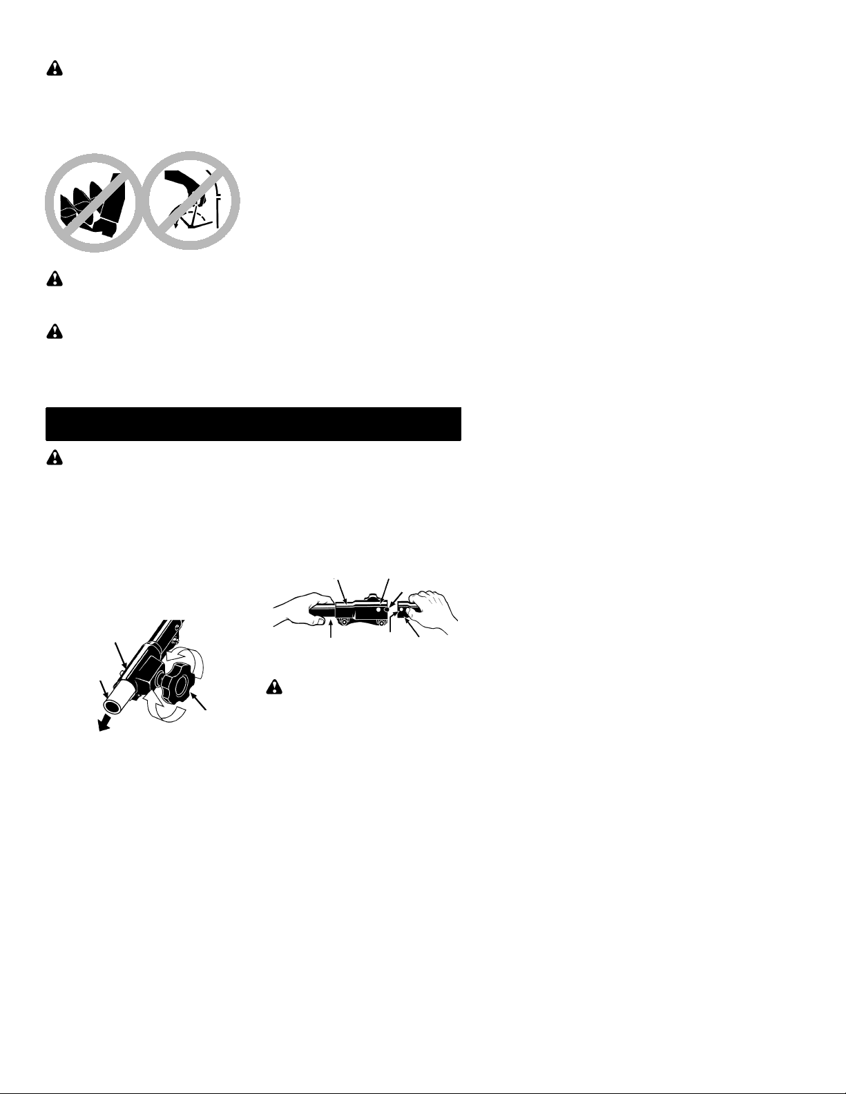
serious injury. Keep away from rotating tines.
Stop the engine and disconnect the spark plug
before unclogging tines or making repairs.
Rotating tines can cause
WARNING:
spin after the throttle is released or engine is
turnedoff. The coasting blade can throw objects or seriously cut you if accidentally
touched. Stop the blade by contacting the
right handside of the coastingbladewith material already cut.
The blade continues to
WARNING:
cultivated beforestarting theunit. Removeall
debris and hard and sharp objects such as
rocks, vines, branches,rope,string, etc.
5
Inspect the area to be
Page 6

S Avoid heavy contact with solid objects that
might stop the tines. If heavy contact occurs, stop the engine and inspect the unit
for damage.
S Neveroperate thecultivatorwithout thetine
cover in place and properly secured.
S Keep the tines and guard clear of debris.
S After striking a foreign object, stop the en-
gine,disconnectthe sparkplugandinspect
thecultivator fordamage. Repairbeforerestarting.
S Disconnect attachment from the drive en-
gine before cleaning the tines with a hose
and water to remove any build--up. Oil the
tines to prevent rust.
S Always wear gloves when servicing or
cleaning the tines. The tines become very
sharp from use.
S Do not run unit at high speed unless culti-
vating.
HEDGE TRIMMERSAFETY
DANGER:
HANDS AWAY FROM BLADE
moves momentarily after the trigger is released. Do notattemptto clear away cut material whentheblade is in motion. Make sure
the switch is in the OFF position, the spark
plug wire is disconnected, and the blade has
stopped moving before removing jammed
materialfromthecuttingblade. Donot grabor
hold the unit by the cutting blade.
RISK OF CUT; KEEP
-- Blade
touch. Toprevent serious injury, always stop
engine and ensure blade/chain has stopped
moving, disconnect spark plug, and wear
gloves when changing or handling the blade
or chain.
WARNING:
chain can cause injury while it continues to
move after the engine is stopped. Maintain
propercontrolofthe unit until the blade/chain
has completely stopped moving. Keep
hands, face and feet at a distance from all
movingparts. Donotattempttotouch orstop
the blade or chain when it is moving.
WARNING:
causesevereheadinjury. Wear headprotectionwhenoperating this unit with a polepruner attachment.
Acoastingblade/rotating
Falling objects can
Blades move
momentarily
after the
trigger is
released.
WARNING:
starting the unit. Remove all debris and hard
objects such as rocks, glass, wire, etc. that
can ricochet, be thrown, or otherwise cause
injury or damageduring operation.
S Do not use a cutting blade that is bent,
warped, cracked, broken or damaged in
any other way. Have worn or damaged
parts replaced by your authorized service
dealer.
S Always keep unit in front of your body.
Keep all parts of your body away from the
cutting blade.
S Keepthecuttingbladeandairventsclear of
debris.
Allow blades to stop
before removing
them from the cut.
Inspect the area before
POLE PRUNER SAFETY
WARNING:
rotating chain can cause severe injury. Inspect theunitbeforeuse. Donot operateunit
withabent,crackedordullbladeor dullchain.
Keepawayfromthe blade/chain.Thereciprocating blade/rotating chain is sharp. Do not
The reciprocating blade/
WARNING:
do not use more than one boom extension
with a pole prunerattachment.
WARNING:
from power lines or electrical wires.
S Only use forpruning limbs or branches up
to 4 inches in diameter.
S Do not operate the unit faster than the
speedneededto prune. Donotrun theunit
at high speed when not pruning.
S Always stop the unit when work is delayed
orwhen walkingfromonecuttinglocation to
another.
S Ifyou strike orbecomeentangledwithafor-
eign object, stop the engine immediately
and check for damage. Have any damage
repaired by an authorized service dealer
before attempting further operations. Discard bladesthatare bent, warped,cracked
or broken.
S Stopthe unit immediately if you feel exces-
sive vibration. Vibrationis a sign oftrouble.
Inspect thoroughly for loose nuts, bolts or
damage beforecontinuing. Contact an authorized service dealer for repair or replacement of affected parts as necessary.
6
Topreventseriousinjury,
Keep the pruner away
Page 7
SNOW THROWERSAFETY
WARNING:
away from the rotor when starting or running
the engine. Never attempt to clear the rotor
with the engine/motor running. Stop engine
anddisconnect spark plug beforeunclogging
snowordebris fromdischargechuteor when
adjusting vanes.
WARNING:
charge chute. Rocks or debris could be
throwninto theeyesand faceand cause serious injury or blindness.
WARNING:
the unit is to be used. Remove objects that
could be thrown or damage the unit. Some
objects may be hidden by fallen snow -- be
alert for thepossibility.
S Direct material discharge away from glass
enclosures, automobiles, etc.
Keep hands and feet
Never lean over dis-
Inspect the area where
ASSEMBLY
S Do not run engine at high speed while not
removing snow.
S Be attentive when using the snowthrower,
and stay alert for holes in the terrain and
other hidden hazards.
S Make sure the rotor will spin freely before at-
taching the snowthrower to the powerhead.
S Iftherotorwillnotrotatefreelyduetofrozen
ice, thaw theunit before thoroughly before
attempting to operate under power.
S Keep the rotor clear of debris.
S Do notthrowsnownearotherpeople. The
snow thrower could propel small objectsat
high speed causing injury.
S After striking a foreign object, stop the en-
gine,disconnectsparkplugandinspectthe
snowthrower for damage and repair if necessary before restarting unit.
S Neveroperatethe snowthrower nearglass
enclosures,automobilesand trucks.Never
attempt to use the snowthrower on a roof.
S Never operate the snowthrower near win-
dow wells, dropoffs,etc.
S Neverdischargesnowonto public roads or
near moving traffic.
S Clear snow from slopes by going up and
down; never across. Use caution when
changingdirections.Neverclear snowfrom
steep slopes.
S Let snowthrower run for a few minutes after
clearing snow so moving parts do not freeze.
S Look behind and use care when backing
up. Exercisecautionto avoidslippingorfalling, especially when operating in reverse.
S Know how to stop quickly.
WARNING:
repeatall steps toensureyourunitisproperly
assembled and all fasteners are secure.
Examine parts for damage. Do not usedamaged parts.
It is normal for the fuel filter to rattle in the
empty fuel tank.
Findingfueloroil residue onmufflerisnormal
due to carburetor adjustments and testing
done by the manufacturer.
If received assembled,
INSTALLINGTRIMMERA TTACHMENT
CAUTION:
ment,placetheunit ona flat surface for stability.
1. Loosen the coupler by turning the knob
counterclockwise.
Shipping
protector
When installing trimmer att ach-
Coupler
TIGHTEN
LOOSEN
Knob
2. Remove shipping protector from coupler.
3. Remove the shaft cap from the trimmer
attachment (if present).
4. Position locking/release button of attachment into guide recess of coupler.
5. Pushtheattachment intothe coupler until
the locking/release buttonsnaps into the
primary hole.
6. Beforeusing theunit,tightenthe knobsecurely by turning clockwise.
Coupler Primary Hole
Upper
Shaft
WARNING:
release button is locked in the primary hole
andthe knob is securely tightened beforeoperatingthe unit. Allattachmentsaredesigned
to be used in the primary hole.
7
Guide Recess
Locking/
Release
Button
Make sure the locking/
Lower
Attachment
Page 8
For optional attachments, see the ASSEMBLY section of the applicable attachment instruction manual.
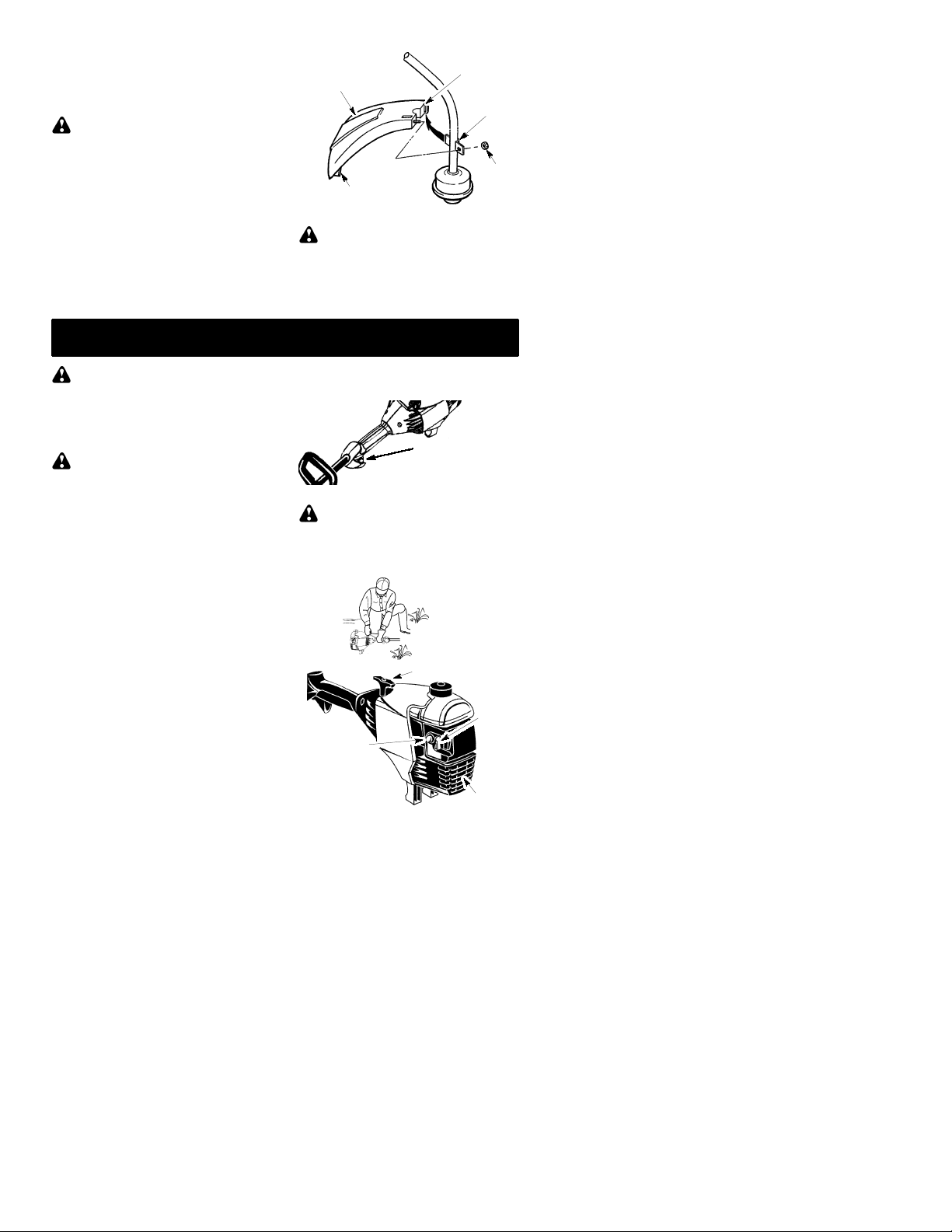
ATTACHING THE SHIELD
WARNING:
erly installed. The shield provides partial
protection from the risk of thrown objects to
theoperatorand others and is equippedwith
a line limiter which cuts excessline. Theline
limiter (on underside of shield) is sharp and
can cut you.
1. Remove nut from shield.
2. Insert bracket into slot on shield.
3. Pivot shield until boltpasses throughhole
in bracket.
4. Reinstall nut and tighten securely with
wrench (provided).
Theshieldmustbeprop-
OPERATION
Shield
Line Limiter Blade
Slot
Bracket
Nut
ADJUSTINGTHE HANDLE
WARNING:
dle, be sure it remains between the trigger
and the safety label. Assist handle must be
positioned only below the arrow.
1. Loosen wing nut on handle.
2. Rotate the handle on the shaft to an upright position; retightenwing nut.
When adjusting the han-
WARNING:
information in the safety rules before you begin.Ifyoudo not understandthe safety rules,
do not attempt to fuel your unit. Contact an
authorized service dealer .
Be sure to read the fuel
FUELING ENGINE
WARNING:
when refueling.
This engine is certified to operate on unleaded
gasoline. Before operation, gasoline must be
mixedwith agoodquality2-cycleair-cooledengine oil. We recommend Partner! brand oil
mixed at a ratio of 40:1 (2.5%). A 40:1 ratio is
obtained by mixing 5 liters of unleadedgasoline
with 0,125 liter of oil. DONOT USEautomotive
oil or boat oil. These oils will cause engine damage. When mixing fuel, follow instructions
printed on oil container. Once oil is added to
gasoline, shake container momentarily to assure that the fuel is thoroughly mixed. Always
read and follow the safety rules relating to fuel
before fueling your unit.
IMPORTANT
Experience indicates that alcohol blended
fuels (called gasohol or using ethanol or
methanol)can attractmoisturewhichleadsto
separationand formationof acids duringstorage. Acidic gas can damage the fuel system
ofanengine whileinstorage.T oavoid engine
problems,emptythefuel system beforestoragefor 30 days or longer.Drainthegas tank,
starttheengineandletitrununtil thefuel lines
andcarburetorareempty.Use fresh fuelnext
season. Never use engine or carburetor
cleanerproductsinthe fueltank orpermanent
damage may occur.
Remove fuel cap slowly
HOW TO STOP YOUR UNIT
S To stop the engine, move the ON/OFF
switch to the OFF position.
ON/OFF Switch
HOW TO STARTYOURUNIT
WARNING:
the muffler. A hot muffler can cause serious
burns.
Avoid any contact with
STARTING A COLD ENGINE (or a
warm engine after running out of fuel)
Starting Position
Starter Handle
Choke
Lever
Primer Bulb
Muffler
8
Page 9
1. Set unit on a flat surface.
2. MoveON/OFFswitch tothe ON position.
3. Slowly press the primer bulb 6 times.
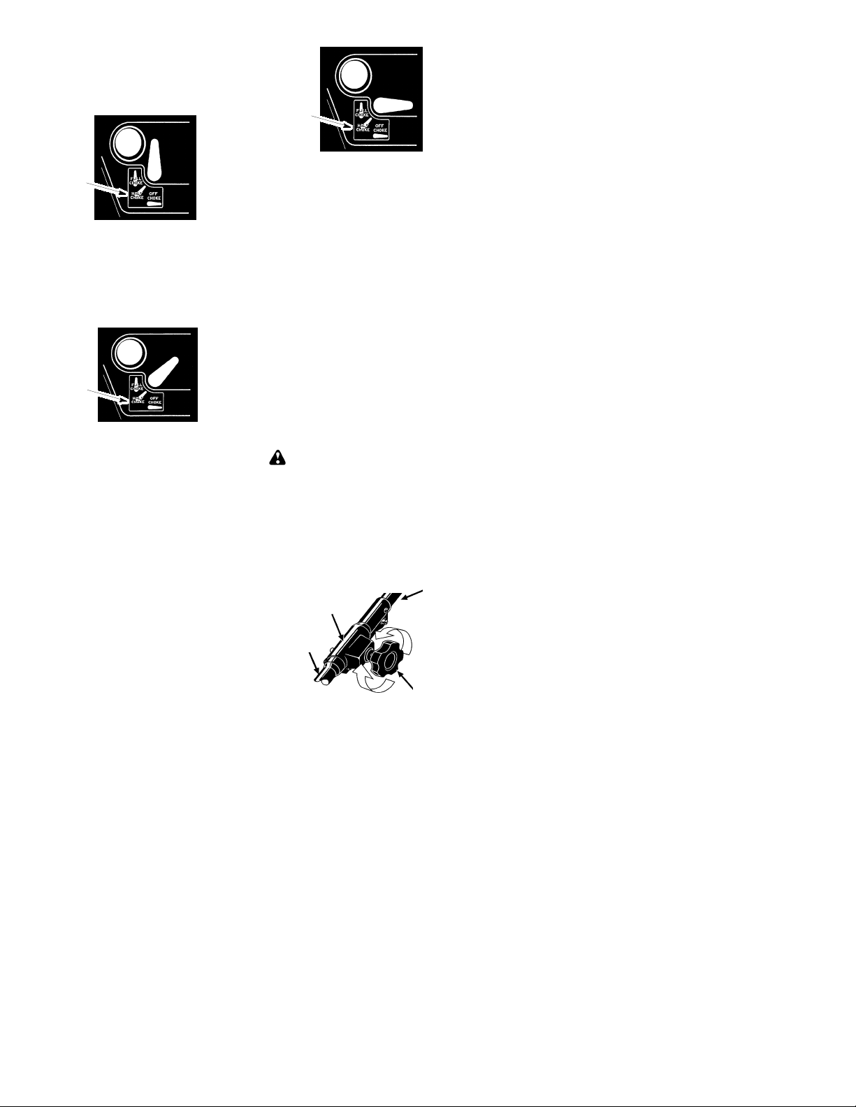
4. Move choke lever to FULL CHOKE position
byaligninglever withpositionshownondecal (see illustra tion below ) .
Choke
position
decal
Choke
position
decal
5. Squeeze and hold trigger through all re-
mainingsteps.
6. Pull starter rope handle sharply until enginesoundsas if it is trying tostart, butdo
not pull rope more than 6 times.
7. As soonasengine sounds as if it is trying
to start, move choke lever to HALF
CHOKE by aligning lever with position
shownon d ecal (see illustration below ) .
Choke
position
decal
8. Pullstarterrope sharplyuntilengineruns,
but no more than 6 pulls. If the engine
doesn’t start after 6 pulls (at the HALF
CHOKE position), move the choke lever
to the FULL CHOKE position and press
theprimer bulb6times.Squeeze andhold
thethrottletrigger andpull thestarterrope
2moretimes.Movethe chokelever tothe
HALF CHOKE position and pull the starter rope until theengineruns,but no more
than 6 pulls.
NOTE:
probably flooded. Proceed toSTARTING
A FLOODED ENGINE.
9. Once the engine starts, allow it to run 10
seconds, then move the choke lever to
OFF CHOKE by aligning lever with position shown on decal (see following illustration). Allow the unit to run for 30
moresecondsatOFFCHOKE beforereleasing the throttle trigger.
NOTE:
verin theOFF CHOKEposition,movethe
choke levertothe HALFCHOKEposition
andpull the ropeuntil engineruns, but no
more than 6 pulls.
If engine still doesn’t start, it is
If engine dies with the choke le-
STARTING A WARM ENGINE
1. MoveON/OFFswitch tothe ON position.
2. Move the choke lever to the HALF
CHOKE position.
3. Squeeze and hold the throttle trigger.
Keep throttle trigger fully squeezed until
the engine runs smoothly.
4. Pullstarterrope sharplyuntilengineruns,
but no more than 5 pulls.
5. Allow engine to run 15 seconds, then
movethechoke lever tothe OFFCHOKE
position.
If engine has not started, pull starter
NOTE:
rope5morepulls. Ifenginestill doesnotrun,it
is probably flooded.
ST ARTING A FLOODED ENGINE
Flooded engines can be started by placing
thechoke lever in theOFF CHOKE position;
then, pull the rope to clear the engine of excessfuel.Thiscouldrequirepullingthestarter
handle many times depending on how badly
the unit is flooded.
If the unit still doesn’t start, refer to TROUBLESHOOTING TABLE.
OPERATING THE COUPLER
This model is equipped with a coupler which
enables optional attachments to be installed.
WARNING:
connect sparkplug beforeremovingorinstalling attachments.
Always stopunitanddis-
REMOVINGTRIMMERATTACHMENT (OR OTHER OPTIONAL ATTACHMENTS)
CAUTION:
tachments, place the unitona flat surfacefor
stability.
1. Loosen the coupler by turning the knob
counterclockwise.
Lower
Attachment
Whenremovingor installingat-
Upper Shaft
Coupler
LOOSEN
TIGHTEN
Knob
9
Page 10
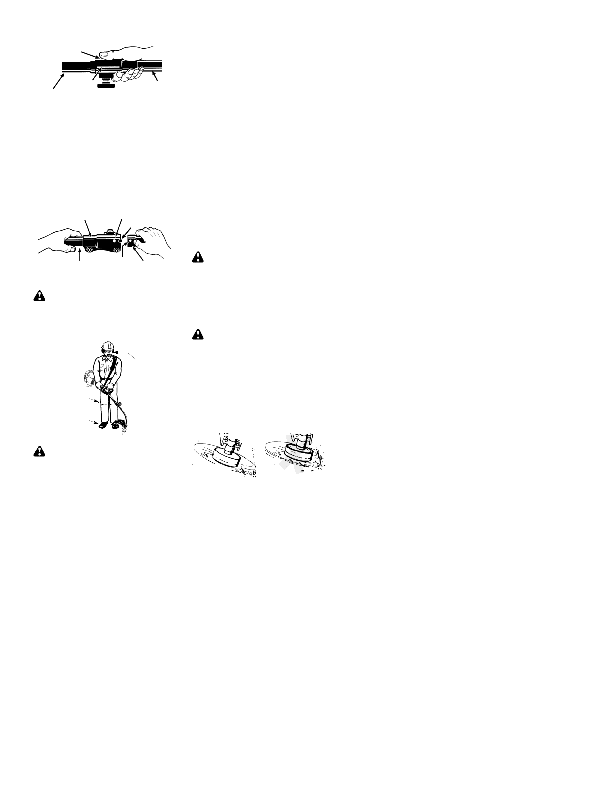
2. Press and hold the locking/release button.
Locking/Release
Button
Lower Attachment
3. While securelyholdingtheengineandup-
Coupler
per shaft, pull the attachment straight out
of the coupler.
Upper Shaft
INSTALLINGOPTIONALATTACHMENTS
1. Remove the shaft cap from the attachment(if present).
2. Position locking/release button of attachment into guide recess of coupler.
3. Pushtheattachment intothe coupler until
the locking/release buttonsnaps into the
primary hole.
4. Beforeusing theunit,tightenthe knobsecurely by turning clockwise.
Coupler
WARNING:
release button is locked in the primary hole
andthe knob is securely tightened beforeoperating the unit.
Upper
Shaft
Primary Hole
Locking/
Release
Guide Recess
Attachment
Button
Make sure the locking/
OPERA TINGPOSITION
ALWAYS WEAR:
Eye Protection
Long Pants
Heavy Shoes
Cut from your right to your left.
Always release the throttle trigger and allow the
engine to return to idle speed when not cutting.
To stop engine:
S Release the throttle trigger.
S Move theON/OFFswitch to the OFF posi-
tion.
TRIMMERLINEADVANCE
Thetrimmer linewill advanceapproximately2
in. (5cm)eachtime the bottomofthe trimmer
headis tappedonthe ground with theengine
running at full throttle.
Themost efficientline lengthis themaximum
length allowed by the line limiter.
Always keep theshield in placewhenthetool
is being operated.
To advance line:
S Operate the engine at full throttle.
S Holdthe trimmer headparallelto andabove
the grassy area.
S Tap the bottom of the trimmer head lightly on
thegroundonetime.Approximately5cmof
line will be advanced with each tap.
Always tap the trimmer head on a grassy
area. Tappingon surfaces such as concrete
or asphalt can cause excessive wear to the
trimmer head.
If the line is worn down to 5 cm or less, more
than one tap will be required to obtain the
most efficient line length.
WARNING:
line.Other sizesandshapesof linewill notadvanceproperlyand will resultin impropercuttinghead functionor cancause seriousinjury.
Do not use other materials such as wire,
string, rope, etc. Wire can break off during
cutting and become adangerousmissile that
can cause serious injury.
Use only 2 mm diameter
CUTTINGMETHODS
WARNING:
do not crowd the line when cutting around
hardobjects (rock, gravel, fence posts, etc.),
whichcandamagethetrimmer head,become
entangled in the line, or be thrown causing a
serious hazard.
S Thetip of the line does the cutting. Youwill
achieve the best performance and mini-
mum line wearbynotcrowdingtheline into
the cutting area. Theright andwrongways
are shown below.
Tip of the Line
Does The Cutting
Useminimum speedand
Line Crowded Into
Work Area
WARNING:
tion and hearing protection. Never lean over
the trimmer head. Rocks or debris can ricochet or be thrown into eyes and face and
cause blindness or other serious injury.
Do not run the engine at a higher speed than
necessary . The cutting line will cut efficient ly
when the engine is run at less than full throttle.
At lower speeds, there is less engine noise and
vibration.Thecuttinglinewill lastlongera ndwill
be less likely to “weld” onto the spool.
Always wear eyeprotec-
Right Wrong
S The line will easily remove grass and
weedsfrom aroundwalls, fences,treesand
flower beds, but it also can cut the tender
bark of trees or shrubs and scar fences.
S For trimming or scalping, use less than full
throttle to increase line life and decrease
head wear,especially:
10
Page 11
S During light duty cutting.
S Near objects around which the line can-
wrap such as small posts, trees or fence
wire.
S Formowingor sweeping,usefull throttlefor
a good clean job.
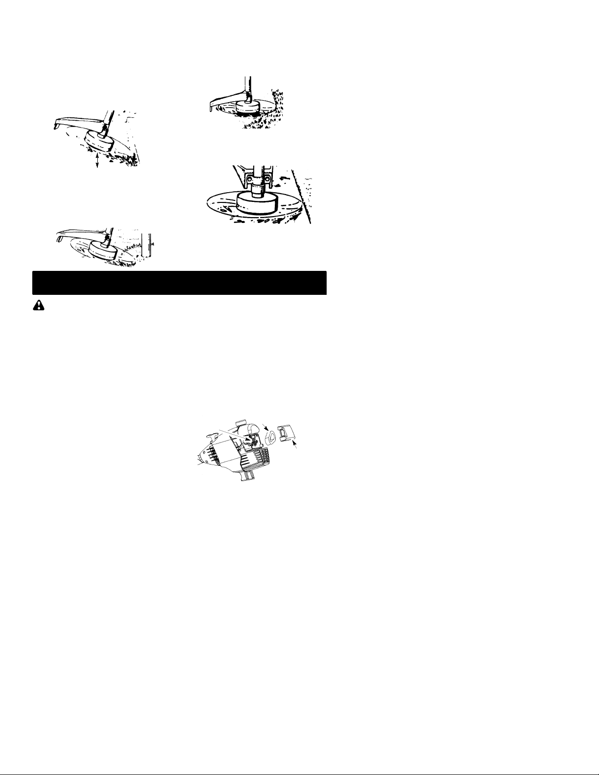
TRIMMING -- Hold the bottom of the trimmer
headabout 80mm above the ground and at an
angle. Allow only the tip of the line to make contact. Do not force trimmer line into work area.
Trimming
80 mm above
ground
SCALPING -- The scalping technique re-
movesunwantedvegetation.Hold thebottom
of the trimmer head about 80 mm above the
groundandatanangle.Allowthe tipof theline
to strike the ground around trees, posts,
monuments, etc. This technique increases
line wear.
Scalping
MAINTENANCE
MOWING -- Your trimmer is ideal for mowing
in places conventional lawn mowers cannot
reach. In the mowing position, keep the line
parallel to the ground. Avoid pressing the
head into the ground as this can scalp the
ground and damage the tool.
Mowing
SWEEPING --Thefanning actionof therotating line can be used for a quick and easy
clean up. Keep the line parallel to and above
the surfaces being swept and move the tool
from side to side.
Sweeping
WARNING:
plug before performing maintenance except
for carburetor adjustments.
Disconnect the spark
CHECK FOR LOOSE
FASTENERSAND PARTS
S Spark Plug Boot
S Air Filter
S Housing Screws
S Assist Handle Screw
S Debris Shield
CHECK FOR DAMAGED OR
WORN PARTS
Contact an authorized service dealer for replacement of damaged or worn parts.
S ON/OFF Switch -- Ensure ON/OFF switch
functions properly by moving the switch to
the OFF position. Make sure engine stops;
then restart engine and continue.
S Fuel Tank -- Discontinue use of unit if fuel
tank shows signs of damage or leaks.
S Debris Shield -- Discontinue use of unit if
debris shield is damaged.
INSPECTAND CLEAN UNIT AND
LABELS
S After each use, inspect complete unit for
loose or damaged parts. Clean the unit and
labels using a damp cloth with a mild deter-
gent.
S Wipe off unit with a clean dry cloth.
CLEAN AIR FILTER
A dirty air filter decreases engine performance and increases fuel consumption and
harmful emissions. Always clean after every
5 hours of operation.
1. Clean the cover andtheareaaroundit to
keep dirt from falling into the carburetor
chamber when the cover is removed.
2. Remove parts as illustrated.
Donotcleanfilteringasoline orother
NOTE:
flammablesolventtoavoidcreatingafirehazard or producing harmful evaporative emissions.
3. Wash the filter in soap and water.
4. Allow filterto dry.
5. Replace parts.
Button
11
Air Filter
Air Filter
Cover
Page 12
REPLACE SPARK PLUG
Replace the spark plug each year to ensure
the engine starts easier and runs better.Set
spark plug gap at 0,6 mm. Ignition timing is
fixed and nonadjustable.
SERVICE AND ADJUSTMENTS
1. Twist, then pull off spark plug boot.
2. Removesparkplug fromcylinderanddiscard.
3. Replace with Champion RCJ-6Y spark
plug and tighten securely with a 19 mm
socket wrench.
4. Reinstall thespark plug boot.
REPLACINGTHELINE
1. Move the ON/OFF switch to the OFF
position.
2. Disconnect the spark plug lead wire.
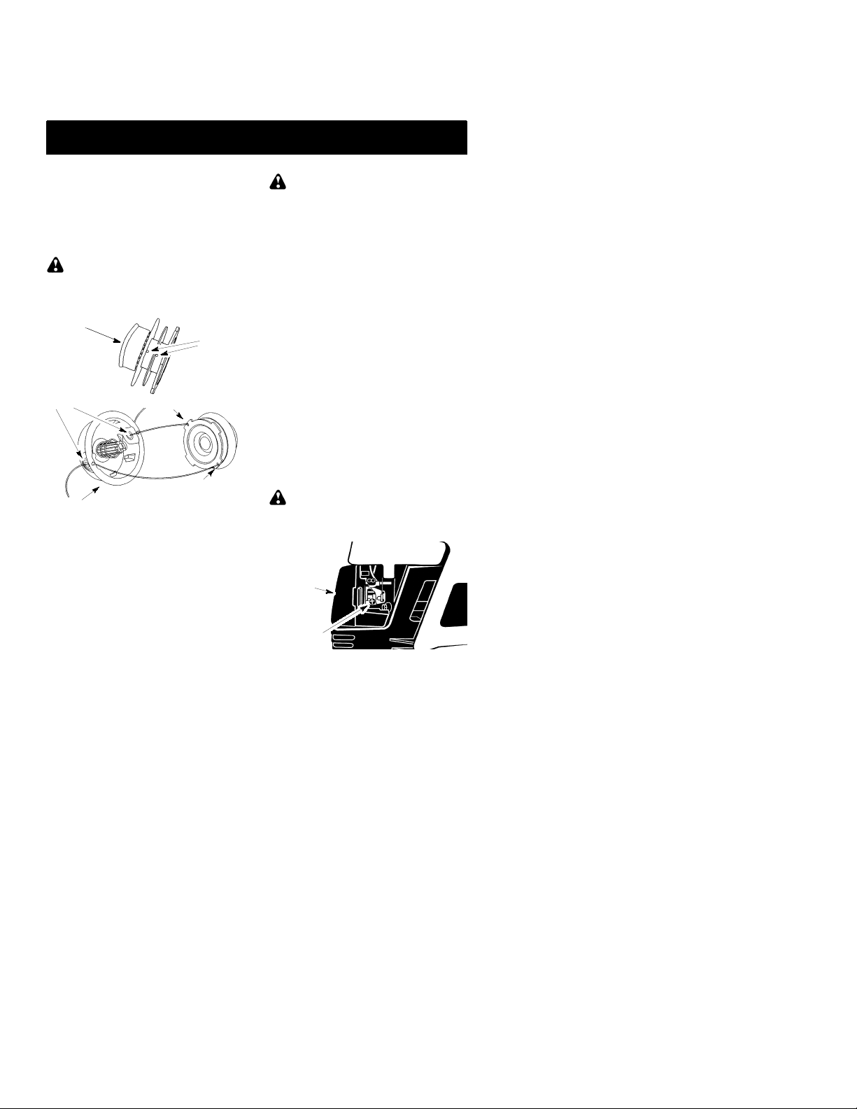
3. Removespoolbyfirmly pullingontapbutton. Clean entire surface of hub and
spool.Replacewith apre-woundspool,or
cut twolengthsof 4meters of2 mm diameter Partnerr brand line.
WARNING:
string,etc.,whichcanbreak offandbecome a
dangerous missile.
4. Insert ends ofthelineabout1 cm into the
small hole on the inside of spool.
Spool
Line exit holes
Hub
5. Wind the line evenly and tightly onto the
spool. Wind inthe direction of the arrows
found on the spool.
6. Pushtheline into the notches,leaving 7-12 cm unwound.
7. Inserttheline into the the exit holes in the
hubas shownin the illustration.
8. Align the notches with the line exit holes.
9. Push spool into hub until it snaps into
place.
10. Pull the linesextendingoutside of thehub
to release them from the notches.
Never use wire, rope,
Small
Holes
Line in Notch
Line in Notch
CARBURETOR ADJUSTMENT
WARNING:
making idle speedadjustments. The trimmer
headwill be spinningduring most of this procedure. Wear yourprotectiveequipmentand
observe all safety precautions. After making
adjustments, the trimmer head must not
move/spin at idle speed.
The carburetor has been carefully set at the
factory.Adjustments may benecessary ifyou
notice any of thefollowing conditions:
S Engine will not idle when the throttle is re-
leased.
S The trimmer head moves/spins at idle speed.
Make adjustments with the unit supported so
the cutting attachment is off the ground and
will not make contact with any object. Hold
theunit byhandwhile runningandmakingadjustments. Keep all parts of your bodyaway
from the cutting attachment and muffler.
Idle Speed Adjustment
Allow engineto idle.Adjustspeed untilengine
runswithouttrimmer headmoving orspinning
(idle speed too fast) or engine stalling (idle
speed too slow).
S Turn idle speed screw clockwise to in-
creaseenginespeedif enginestalls ordies.
S Turnidle speed screw counterclockwise to
decrease engine speed if trimmer head
moves or spins at idle speed.
WARNING:
after each adjustment. The trimmer head
must not move or spin at idle speed to avoid
serious injury to the operator or others.
Air Filter
Cover
Idle Speed
Screw
Ifyou requirefurtherassistance orareunsure
about performing this procedure, contact an
authorized service dealer .
Keep others away when
Recheck the idle speed
12
Page 13

STORAGE
WARNING:
steps after each use:
S Allowenginetocoolbeforestoring ortrans-
porting.
S Store unit and fuel in awell ventilated area
where fuel vapors cannot reach sparks or
open flames from water heaters, electric
motors or switches, furnaces, etc.
S Emptyfueltankbefore storing ortransport-
ing the unit.
S Store unit and fuel well out of the reach of
children.
S Store unit with all guards in place. Position
unit so that any sharp object cannot accidentally cause injury.
SEASONALSTORAGE
Prepareunit forstorageat endofseason or if
it will notbe used for 30 days or more.
If your unitis to bestoredfor a period of time:
S Clean the entire unit before lengthy stor-
age.
S Store in a clean dry area.
S Lightly oil external metal surfaces.
Perform the following
ENGINE
S Removesparkplugand pour1 teaspoonof
40:1,2-cycleengineoil (air cooled) through
the spark plug opening. Slowly pull the
starter rope 8 to 10 times to distribute oil.
S Replacesparkplugwith newone ofrecom-
mended type and heat range.
S Clean air filter.
S Check entire unit for loose screws, nuts,
and bolts. Replace any damaged, broken,
or worn parts.
S At the beginning of the next season, use
only freshfuel havingthepropergasolineto
oil ratio.
OTHER
S Do not store gasoline from one season to
another.
S Replaceyourgasoline canifit startstorust.
13
Page 14
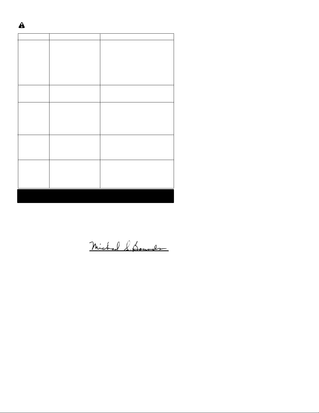
TROUBLESHOOTING T ABLE
WARNING:
recommended remedies below except remedies that require operation of the unit.
Always stopunit anddisconnect sparkplugbeforeperformingall ofthe
TROUBLE CAUSE REMEDY
Enginewill not
start.
Enginewill
not idle
properly.
Enginewill not
accelerate,
lacks power,
or dies under
a load.
Engine
smokes
excessively.
Engine runs
hot.
1. ON/OFF switch in OFF
position.
2. Engine flooded.
3. Fuel tank empty.
4. Spark plug not firing.
5. Fuel not reaching
carburetor.
6. Carburetor requires
adjustment.
1. Carburetorrequires
adjustment.
2. Crankshaft seals worn.
3. Compression low.
1. Air filter dirty.
2. Spark plug fouled.
3. Carburetor requires
adjustment.
4. Carbon build-up on
muffler outlet screen.
5. Compression low.
1. Choke partially on.
2. Fuel mixture incorrect.
3. Air filter dirty.
4. Carburetor requires
adjustment.
1. Fuel mixture incorrect.
2. Spark plug incorrect.
3. Carburetorrequires
adjustment.
4. Carbon build-up on
muffler outlet screen.
1. Move ON/OFF switch to ON position.
2. See “Starting a Flooded Engine” in
Operation Section.
3. Fill tank with correct fuel mixture.
4. Install new spark plug.
5. Check for dirty fuel filter; replace.
Check for kinked or split fuel line;
repair or replace.
6. Contact an authorized service dealer.
1. See “Carburetor Adjustment” in
Service and Adjustments Section.
2. Contact an authorized service dealer.
3. Contact an authorized service dealer.
1. Clean or replace air filter.
2. Clean or replace plug
and regap.
3. Contact an authorized service dealer.
4. Contact an authorized service dealer.
5. Contact an authorized service dealer.
1. Adjust choke.
2. Empty fuel tank and refill with
correct fuel mixture.
3. Clean or replace air filter.
4. Contact an authorized service dealer.
1. Empty fuel tank andrefill with
correct fuel mixture.
2. Replace with correct spark plug.
3. Contact an authorized service dealer.
4. Contact an authorized service dealer.
DECLARATION OF CONFORMITY
relating to 2000/14/EC
EC Declaration of Conformity relating to 2000/14/EC
We, Electrolux Home Products,Inc., Texarkana, TX, 75501, USA, Tél. : +1 903 223
4100,declare undersole responsibility thatthe Partnermodel T280grass trimmer was
assessed in accordance with Annex V of the DIRECTIVE and from serial numbers
2003--246N00001 and onwards, conforms to the provisions of the DIRECTIVE. The
cuttingwidthis 431 mm. Themeasuredsound poweris 108dB andthe guaranteedsound
power is 118 dB.
Texarkana 03--09--03
Michael S. Bounds, Director
Product Safety and Standards
14
Page 15

DECLARATION OF CONFORMITY
relating to 98/37/EC
EC Declaration of Conformity (Directive 98/37/EC,Annex II, A) (Only applies to
Europe)
We, Electrolux Home Products, Inc., Texarkana,TX, 75501, USA, Tél. : +1 903 223
4100,Declare under sole responsibility that the Partnermodel T280 grass trimmerfrom
serial numbers 2003--246N00001 and onwards, follows the provisions of the
DIRECTIVES: 98/37/EC (machinery) and 89/336/EEC (electromagnetic compatibility),
including amendments and is in conformity with the following standards: EN 292--2, EN
ISO 11806 andCISPR 12.
SMP, TheSwedishMachinery TestingInstitute, Fyrisborgsgatan3 S--75450Uppsala,
Sweden, has carried out voluntary type approval. The certificate(s) are numbered:
SEC/04/1009
Texarkana 03--09--03
.
Michael S. Bounds, Director
Product Safety and Standards
TECHNICAL DATA SHEET
M
ODEL: T280
ENGINE
Displacement, cm
Maximum enginepower, measured in
accordance with ISO 8893, kW 0,7
ENGINE ROTATIONALSPEEDS
At maximum engine power,rpm 10000
Recommended maximum speed, rpm 8260
Recommended speed idling, rpm 3000
FUEL AND LUBRICATION SYSTEM
Fuel tank volume capacity, cm
Fuel consumption at maximum engine power,
measured in accordance with ISO 8893,g/h 399
Specified fuel consumption at max. enginepower,
measured in accordance with ISO 8893,g/kWh 435
WEIGHT
Without cutting attachment or shield, empty tank, kg 5
CUTTING ATTACHMENT
Cutting head assembly, part number #530058831
NOISE LEVELS (Octave Band Analysis100--10000hz 1/3 Octave)
SOUND PRESSURE LEVELS in accordance with ISO/EN 11806
measured in accordance with EN 27917,dB(A) 95,6
SOUND POWER LEVELSin accordance with ISO/EN 11806
measured in accordance with ISO/EN 10884,dB(A) 105,7
VIBRATION LEVELS measured in accordance with ISO 7916
FRONT HANDLE
Idling, m/s
Racing, m/s
REAR HANDLE
Idling, m/s
Racing, m/s
3
3
2
2
2
2
28
325
9,18
7,33
20,1
10,1
YEAR OF CONSTRUCTION: 2004
MANUFACTURER’S ADDRESS: Electrolux Home Products, Inc.
104 Warren Road
Augusta, GA 30907
15
 Loading...