

Partner SP-800 Service Manual

POS Terminal
SP-800
Service Manual


i
Copyright
This publication, including all photographs, illustrations and software, is protected under international
copyright laws, with all rights reserved. Neither this manual, nor any of the material contained herein, may be
reproduced without written consent of the author.
Disclaimer
The information in this document is subject to change without notice. The manufacturer makes no representa-
tions or warranties with respect to the contents hereof and specically disclaims any implied warranties of
merchantability or tness for any particular purpose. The manufacturer reserves the right to revise this publi-
cation and to make changes from time to time in the content hereof without obligation of the manufacturer to
notify any person of such revision or changes.
Trademark recognition
All product names used in this manual are the properties of their respective owners and are acknowledged.
Federal Communications Commission (FCC)
This equipment has been tested and found to comply with the limits for a Class A digital device, pursuant to
Part 15 of the FCC Rules. These limits are designed to provide reasonable protection against harmful interference in a residential installation. This equipment generates, uses, and can radiate radio frequency energy
and, if not installed and used in accordance with the instructions, may cause harmful interference to radio
communications. However, there is no guarantee that interference will not occur in a particular installation. If
this equipment does cause harmful interference to radio or television reception, which can be determined by
turning the equipment off and on, the user is encouraged to try to correct the interference by one or more of
the following measures:
Reorient or relocate the receiving antenna.
Increase the separation between the equipment and the receiver.
Connect the equipment onto an outlet on a circuit different from that to which the receiver is connected.
Consult the dealer or an experienced radio/TV technician for help.
Shielded interconnect cables and a shielded AC power cable must be employed with this equipment to ensure
compliance with the pertinent RF emission limits governing this device. Changes or modications not expressly approved by the system’s manufacturer could void the user’s authority to operate the equipment.
Declaration of conformity
This device complies with part 15 of the FCC rules. Operation is subject to the following conditions:
This device may not cause harmful interference, and
This device must accept any interference received, including interference that may cause undesired operation.

ii
About this manual
The service manual provides service information for the SP-800. This manual is designed to help train service
personnel to locate and x failing parts on the machine.
This manual consists of the following sections:
Chapter 1 Getting Started:
This section covers unpacking and checking the package contents, and identifying components.
Chapter 2 BIOS Setup Utility:
The BIOS chapter provides information on navigating and changing settings in the BIOS Setup
Utility.
Chapter 3 Installing Drivers and Software:
This chapter provides information for installing drivers.
Chapter 4 Locating the Problem:
Refer to this chapter to locate the failing part or cause of the problem that requires servicing.
Chapter 5 Replacing Field Replaceable Units (FRUs):
This chapter provides drawings and instructions to replace all FRUs.
Appendix: Optional Components, Exploded Diagram, and Parts List:
The appendix includes an exploded diagram of the machine and the parts list and order number for
each part.
Safety information
Before servicing the machine, read the safety information under “Safety and precautions” on page 45.
Revision history
Version 1.0, October 2011

iii
TABLE OF CONTENTS
CHAPTER 1 GETTING STARTED ................................................ 1
Unpacking the machine .................................................................................1
Identifying components .................................................................................2
CHAPTER 2 BIOS SETUP ............................................................ 5
About the Setup Utility ...................................................................................5
Entering the Setup Utility ..........................................................................6
BIOS navigation keys ................................................................................6
Using BIOS ...............................................................................................7
Main Screen ...................................................................................................8
Advanced Settings .........................................................................................9
IDE Conguration ....................................................................................10
Primary/ Secondary IDE Master ..............................................................11
MPS Conguration ...................................................................................12
SuperIO Conguration .............................................................................13
Hardware Health Conguration ...............................................................14
ACPI Conguration ..................................................................................15
USB Conguration ...................................................................................16
Boot Settings Conguration .........................................................................17
Boot Device Priority .................................................................................18
Hard Disk Drives ......................................................................................19
Boot Settings Conguration .....................................................................20
Chipset Settings ...........................................................................................21
North Bridge Chipset Conguration .........................................................22
South Bridge Chipset Conguration ........................................................23
Security Settings ..........................................................................................24
Exit Menu .....................................................................................................25
CHAPTER 3 INSTALLING DRIVERS AND SOFTWARE ............ 27
Driver auto installation..................................................................................27
Intel Chipset Driver.......................................................................................28
Intel Chipset Graphics Driver .......................................................................30
LAN Driver ....................................................................................................32
Touch Screen Driver.....................................................................................34
Calibrating the touchscreen .....................................................................37

iv
CHAPTER 4 LOCATING THE PROBLEM .................................. 39
General checkout guidelines ........................................................................39
Cash drawer checkout .................................................................................39
LCD symptoms .............................................................................................40
Touch screen symptoms ..............................................................................41
Power symptoms..........................................................................................41
Network symptoms .......................................................................................41
USB symptoms ............................................................................................42
Peripheral-device symptoms ........................................................................42
Boot symptoms ............................................................................................42
Mainboard jumper ........................................................................................43
Mainboard connectors..................................................................................44
Inverter connectors ......................................................................................44
CHAPTER 5 REPLACING FIELD REPLACEABLE UNITS (FRUs)
..................................................................................................... 45
Safety and precautions ................................................................................45
Before you begin ..........................................................................................46
Replacing parts ............................................................................................46
HDD .............................................................................................................47
IO Panel Cover.............................................................................................48
Stand Base Back Cover ...............................................................................48
Stand Base...................................................................................................49
Back Cover...................................................................................................50
Speaker ........................................................................................................51
Power Button................................................................................................51
COM4 port and PS/2 Port ............................................................................52
I/O Shield .....................................................................................................52
Memory ........................................................................................................53
Battery ..........................................................................................................53
Mainboard ....................................................................................................54
Inverter .........................................................................................................54
Panel Bracket ...............................................................................................55
Waterproof Seal, Touch Panel, Touch Cover, LCD Panel ............................56
APPENDIX PART LIST AND SPECIFICATION ........................... 57
Part list for aluminum cover..........................................................................59
Part list for plastic cover ...............................................................................60
Specications ...............................................................................................61

v
LIST OF FIGURES
Figure 1.1 Unpacking the machine ......................................................... 1
Figure 1.2 Front-right view ...................................................................... 2
Figure 1.3 Rear view ............................................................................... 3
Figure 1.4 SP-800 I/O connectors........................................................... 4
Figure 2.1 Main BIOS screen .................................................................. 6
Figure 2.2 Main Screen ........................................................................... 8
Figure 2.3 Advanced Settings Screen ..................................................... 9
Figure 2.4 IDE Conguration sub-menu................................................ 10
Figure 2.5 Primary/ Secondary IDE Master sub-menu ..........................11
Figure 2.6 MPS Conguration sub-menu .............................................. 12
Figure 2.7 SuperIO Conguration sub-menu ........................................ 13
Figure 2.8 Hardware Health Conguration sub-menu........................... 14
Figure 2.9 ACPI Settings sub-menu ...................................................... 15
Figure 2.10 USB Conguration sub-menu ............................................ 16
Figure 2.11 Boot Settings screen .......................................................... 17
Figure 2.12 Boot Device Priority sub-menu .......................................... 18
Figure 2.13 Hard Disk Drives sub-menu ............................................... 19
Figure 2.14 Boot Settings Conguration sub-menu .............................. 20
Figure 2.15 Chipset Settings screen ..................................................... 21
Figure 2.16 North Bridge Chipset Conguration sub-menu .................. 22
Figure 2.17 South Bridge Chipset Conguration sub-menu.................. 23
Figure 2.18 Security Settings screen .................................................... 24
Figure 2.19 Exit Menu screen ............................................................... 25
Figure 4.1 Connecting a cash drawer ................................................... 40
Figure 4.2 SP-800 mainboard jumper ................................................... 43
Figure 4.3 SP-800 mainboard connectors ............................................ 44
Figure 4.4 Inverter connectors .............................................................. 44
Figure 6.1 Exploded diagram main parts .............................................. 57
Figure 6.2 Exploded peripheral parts .................................................... 58

vi
1
CHAPTER 1
GETTING STARTED
This chapter describes how to unpack and identifying components on the device. The following topics are
described.
• Unpacking the machine on page 1
• Identifying components on page 2
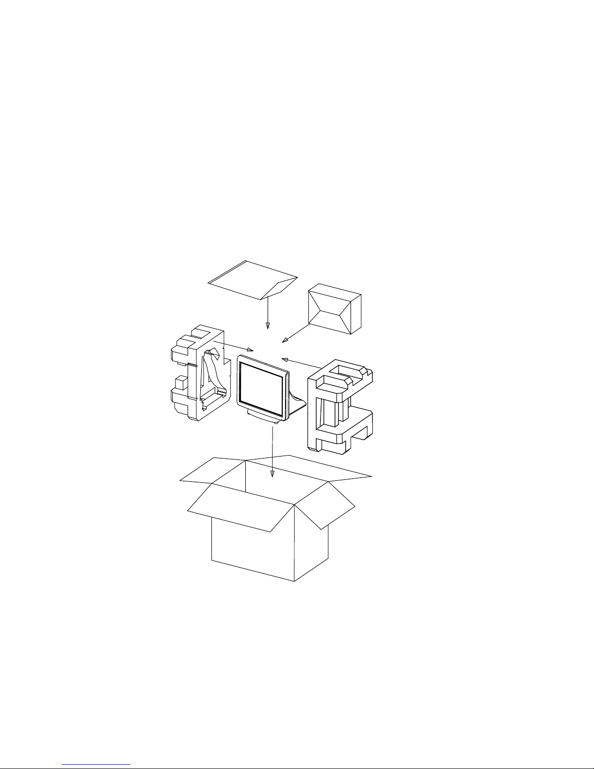
Unpacking the machine
It is a good idea to save the packaging materials and shipping box in case that machine needs to be returned
for service. Please un-pack and re-pack the machine terminal as shown in Figure 1.1.
Figure 1.1 Unpacking the
machine
PE bag
Accessories box
EPE/L
EPE/R
Carton
2 C H A P T E R 1 G E T T I N G S T A R T E D
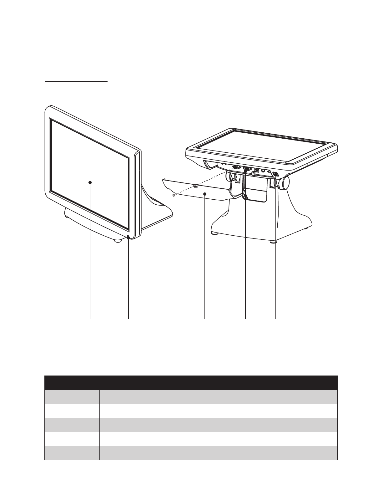
Identifying components
This section describes the parts and connectors on the machine.
1 2
Figure 1.2 Front-right view
Component Description
1 15-inch TFT LCD
2 LED Power Indicator
3 IO Panel Cover
4 IO Panel
5 Power Button
43 5
Front-right view
3
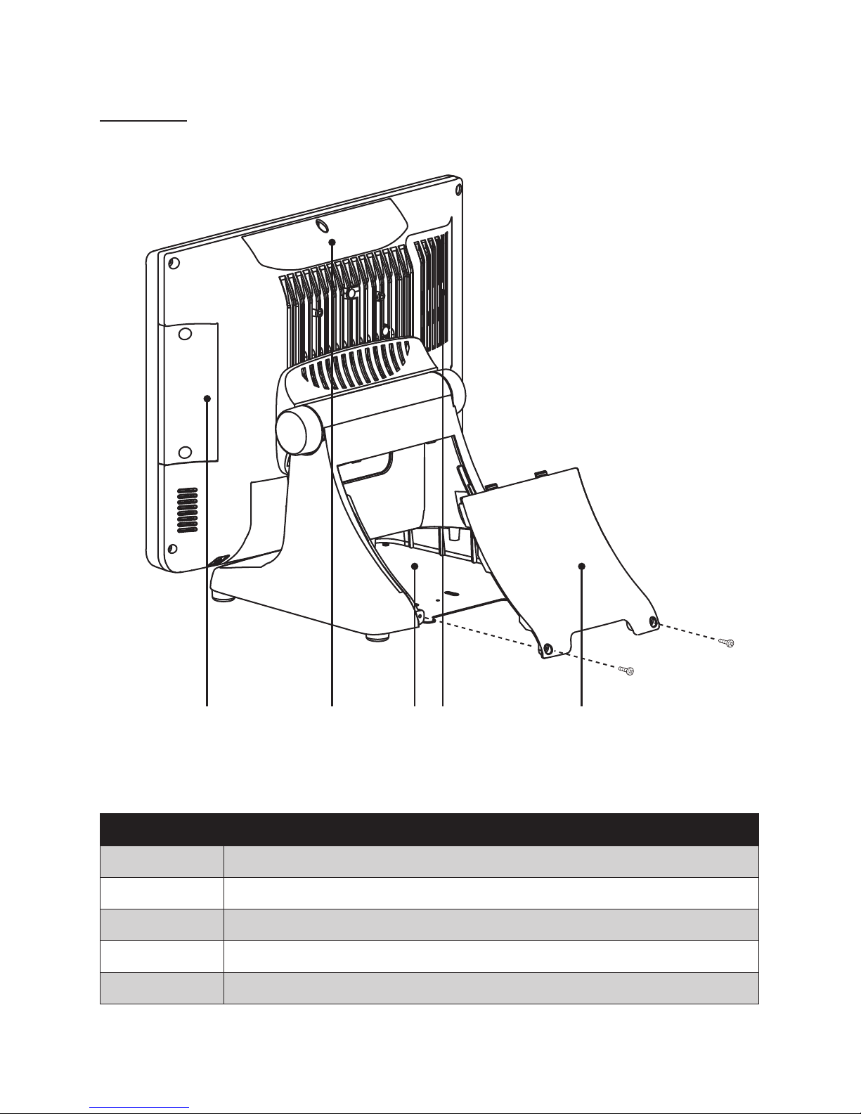
Rear view
1 2 43 5
Figure 1.3 Rear view
Component Description
1 MSR (optional) Slot
2 VFD Customer Display (optional) Slot
3 Cable Compartment
4 HDD Compartment
5 Cable Compartment Cover
4 C H A P T E R 1 G E T T I N G S T A R T E D
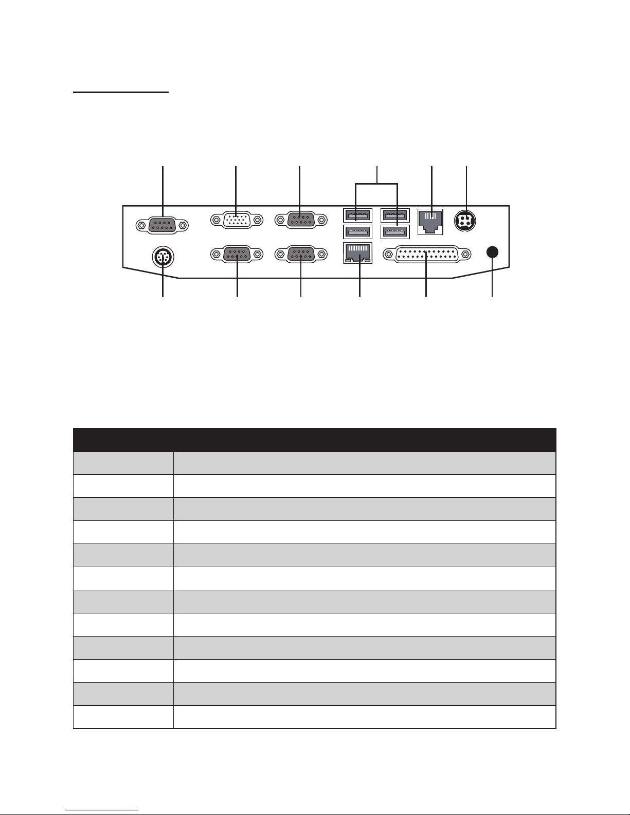
I/O connectors
Figure 1.4 SP-800 I/O connectors
6321 4 5
7 8 9 10 11 12
Connector Description
1 COM 4 port
2 VGA port
3 COM 1 port
4 USB ports
5 RJ-11 cash drawer port
6 DC 12V input connector
7 PS/2 port
8 COM 3 port
9 COM 2 port
10 LAN jack
11 Parallel port
12 DC 12V output connector (for Partner LCD Monitor)

5
CHAPTER 2
BIOS SETUP
The primary function of the BIOS (Basic Input and Output System) is to identify and initiate component
hardware. The BIOS parameters are stored in non-volatile BIOS memory (CMOS). CMOS contents don’t get
erased when the computer is turned off. The following topics are described in this chapter.
• About the Setup Utility on page 5
• Main Screen on page 8
• Advanced Settings on page 9
• Boot Settings Conguration on page 17
• Chipset Settings on page 21
• Security Settings on page 24
• Exit Menu on page 25
About the Setup Utility
The BIOS Setup Utility enables you to congure the following items:
• Hard drives, diskette drives, and peripherals
• Video display type and display options
• Password protection from unauthorized use
• Power management features
This Setup Utility should be used for the following:
• When changing the system conguration
• When a conguration error is detected and you are prompted to make changes to the Setup Utility
• When trying to resolve IRQ conicts
• When making changes to the Power Management conguration
• When changing the User or Supervisor password
6 C H A P T E R 2 B I O S S E T U P
Entering the Setup Utility
When you power on the system, BIOS enters the Power-On Self Test (POST) routines. POST is a series of
built-in diagnostics performed by the BIOS. After the POST routines are completed, the following message
appears:
Press DEL to run Setup
Press the delete key <Delete> to access the BIOS Setup Utility:
BIOS navigation keys
The BIOS navigation keys are listed below.
Key Function
← → Select screens
↑ ↓ Select items
+ – Modies the selected eld’s values
Enter Go to sub screen
F1 Displays a screen that describes all key functions
F10 Saves the current conguration and exits Setup
Esc Exits the current screen
Figure 2.1 Main BIOS screen

7
Using BIOS
When you start the Setup Utility, the main screen appears. The main screen of the Setup Utility displays a list
of the options that are available. A highlight indicates which option is currently selected. Use the cursor arrow
keys to move the highlight to other options. When an option is highlighted, execute the option by pressing
<Enter>.
Some options lead to pop-up dialog boxes that prompt you to verify that you wish to execute that option.
Other options lead to dialog boxes that prompt you for information.
Some options (marked with a triangle ►) lead to sub screens that enable you to change the values for the
option. Use the cursor arrow keys to scroll through the items in the sub screen.

8 C H A P T E R 2 B I O S S E T U P
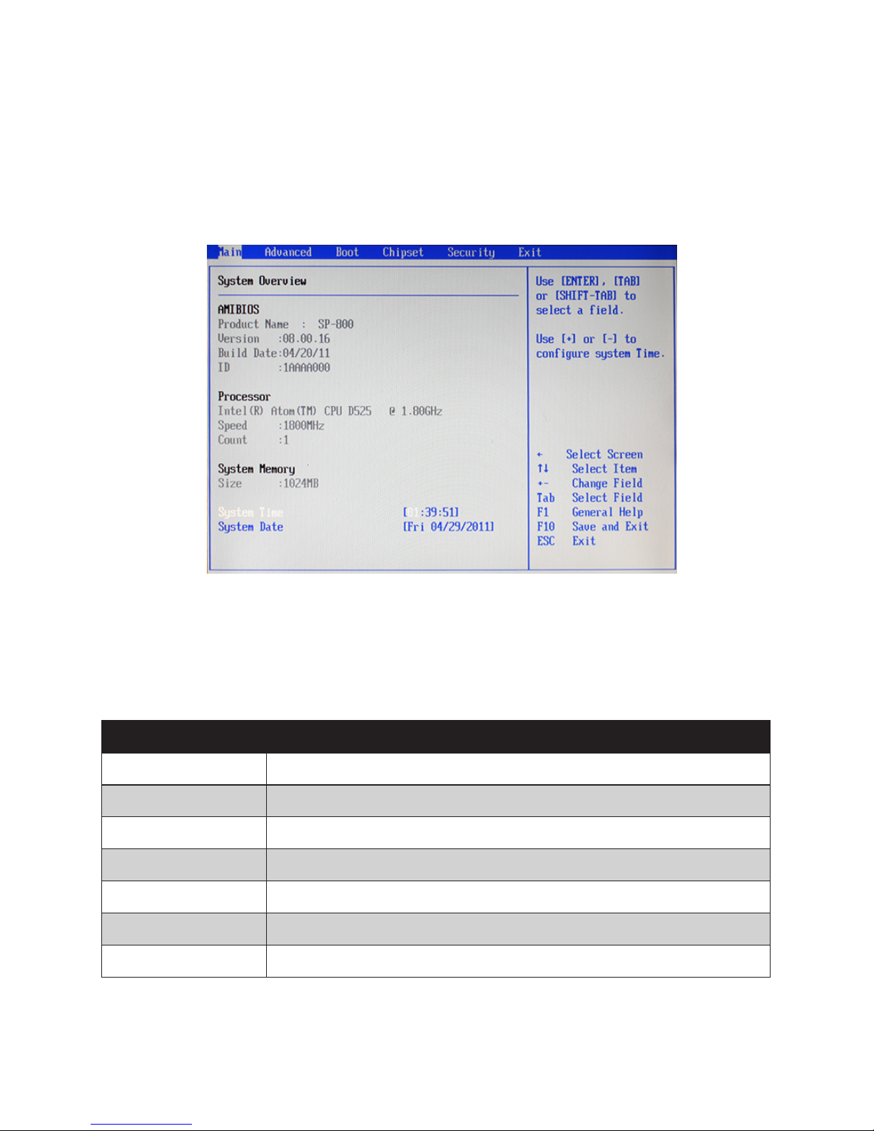
Main Screen
This screen includes System BIOS Information, Processor, System memory and displays the System Time
and System Date.
System Overview
This screen displays System BIOS Information, Processor, System memory, System Time and System Date.
System Time/ System Date
The System Time and System Date items show the current date and time held by the machine. If you are
running a Windows OS, these items are automatically updated whenever you make changes to the Windows
Time and Date Properties utility.
Figure 2.2 Main Screen
9
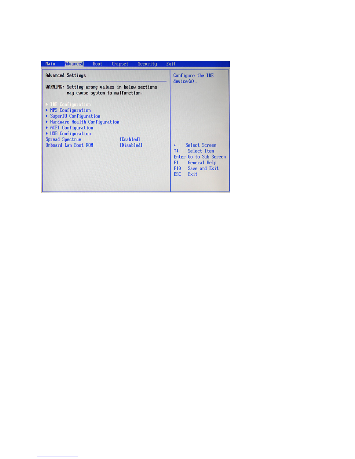
Advanced Settings
This setup screen includes sub-menus for IDE Conguration, USB Conguration, ACPI Congurations, MPS
Congurations, Super IO Congurations and Hardware Health Conguration.
Spread Spectrum
When the motherboard clock generator pulses, the extreme values (spikes) of the pulses creates EMI
(Electromagnetic Interference). The Spread Spectrum function reduces the EMI generated by modulating the
pulses so that the spikes of the pulses are reduced to atter curves. If you do not have any EMI problem, leave
the setting at Disabled for optimal system stability and performance.
Onboard LAN Boot ROM
This feature allows users to enable or disable the onboard Lan boot ROM to boot system.
Figure 2.3 Advanced
Settings Screen
10 C H A P T E R 2 B I O S S E T U P
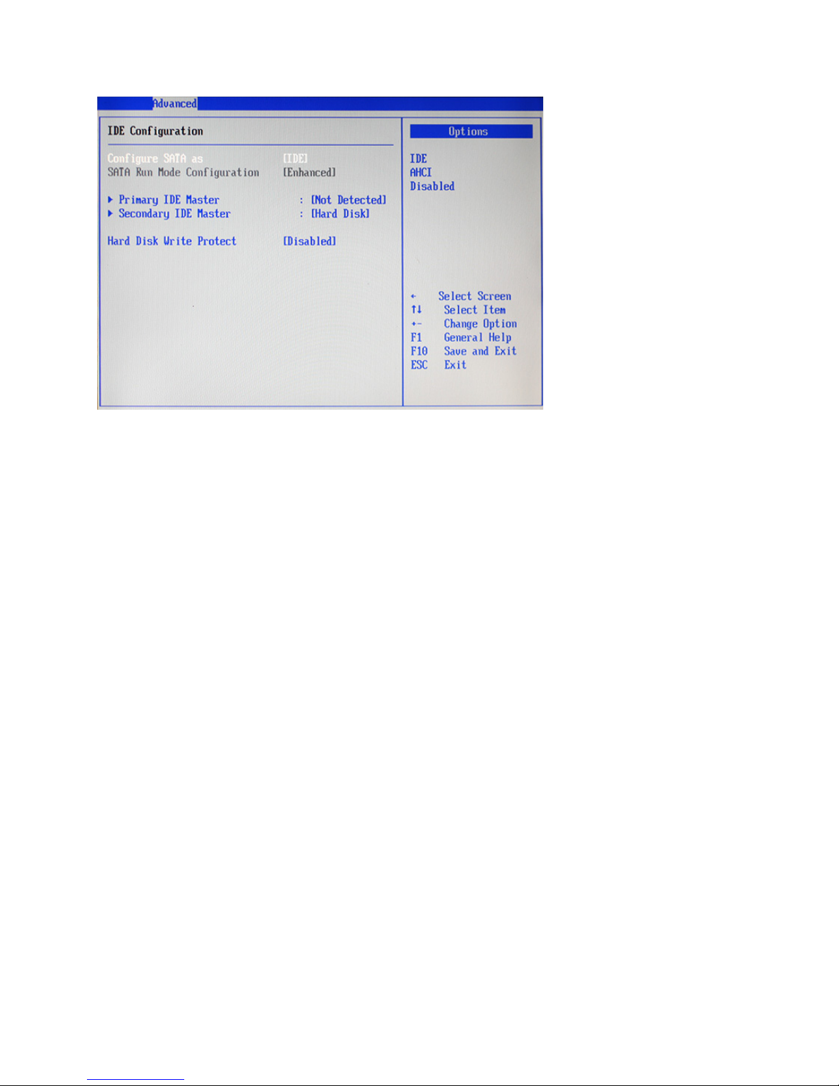
IDE Conguration
Hard Disk Write Protect
This item will be effective only if the device is accessed through BIOS.
Figure 2.4 IDE
Conguration sub-menu
11
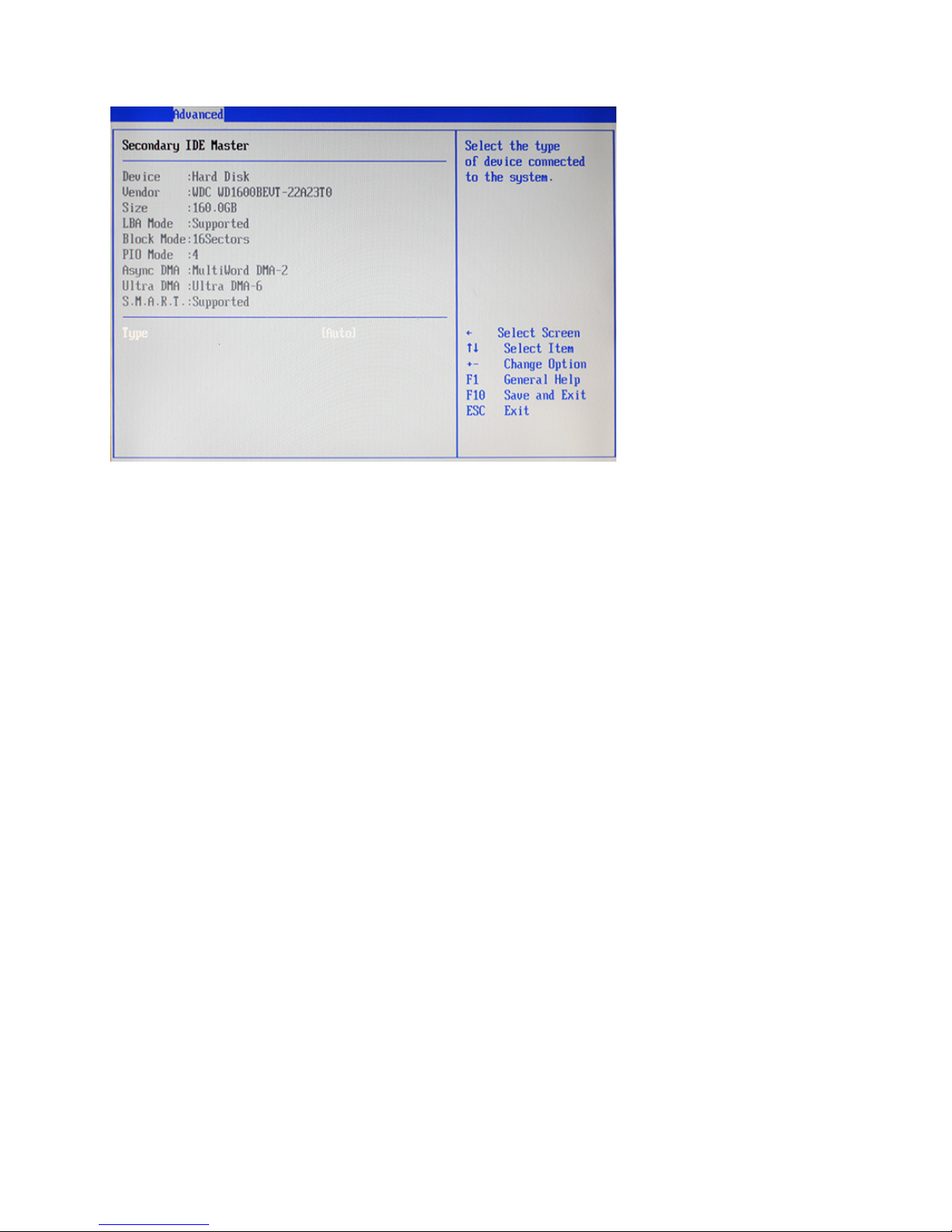
Primary/ Secondary IDE Master
Type
Select [Auto] to automatically detect hard disk drive. If auto detection is successful, the BIOS Setup
automatically lls in the correct values for the remaining elds on this sub-menu. If the auto detection fails, it
may due to that the hard disk is too old or too new. If the hard disk was already formatted on an older system,
the BIOS Setup may detect incorrect parameters. In these cases, select [User] to manually enter the IDE hard
disk drive parameters.
LBA/Large Mode
This allows user to select the LBA/Large mode for a hard disk > 512 MB under DOS and Windows; for
Netware and UNIX user, select [Off] to disable the LBA/Large mode.
Block (Multi-Sector Transfer)
Set this item to [On] will enhance hard disk performance by reading or writing more data during each transfer.
PIO Mode
This item is used to select the IDE PIO (Programmable I/O) mode program timing cycles between the IDE
drive and the programmable IDE controller. As the PIO mode increases, the cycle time decreases.
DMA Mode
This allows user to select the Direct Memory Access (DMA) mode.
S.M.A.R.T.
This item is used to enable monitoring of hard disks that support the S.M.A.R.T. (Self-Monitoring And
Reporting Technology) feature, which can allow the hard disk to report, under some circumstances,
impending failures of the hard disk.
32Bit Data Transfer
It allows user to enable 32-bit access to maximize the IDE hard disk data transfer rate.
Figure 2.5 Primary/
Secondary IDE Master
sub-menu
12 C H A P T E R 2 B I O S S E T U P
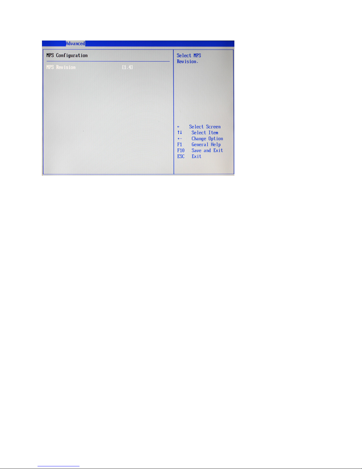
MPS Conguration
MPS Revision
This item allows user to select the version of the Multi-Processor Specication (MPS).
Figure 2.6 MPS
Conguration sub-menu
13
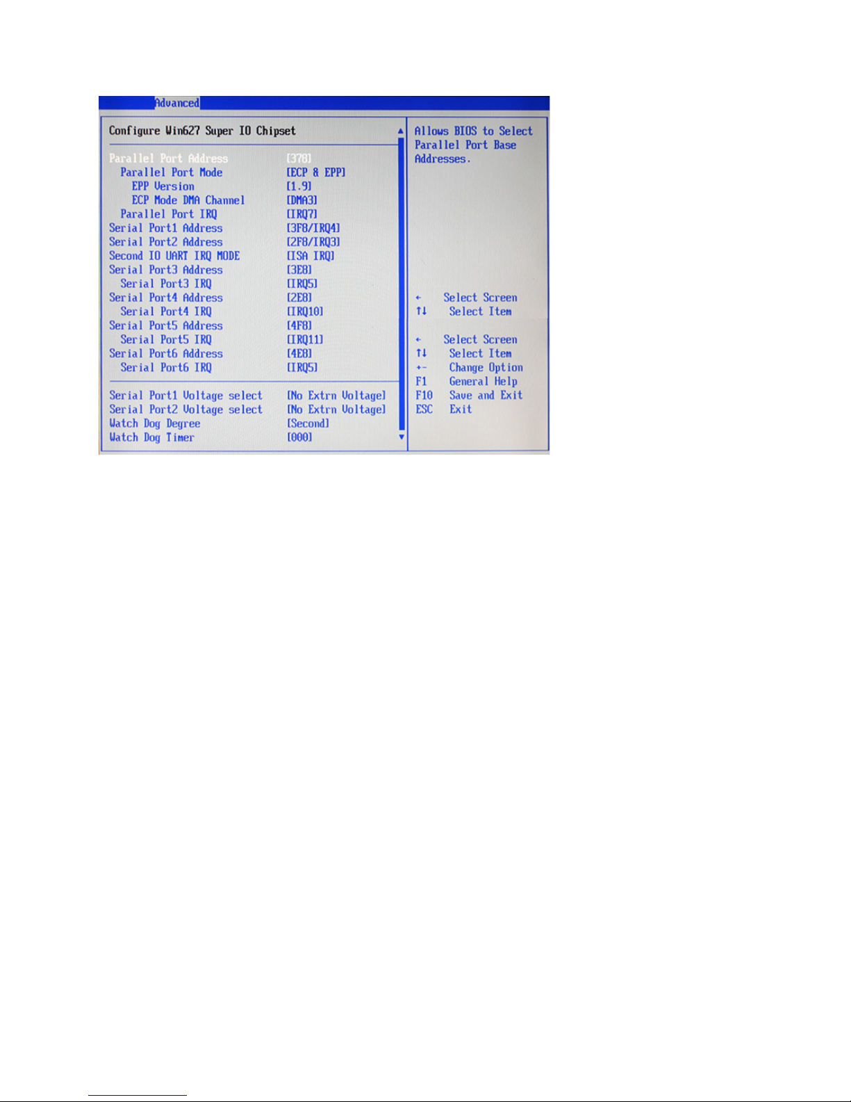
SuperIO Conguration
Parallel Port Address
This item allows user to select the I/O address for the parallel port.
Parallel Port Mode
This item allows user to select the parallel port mode.
EPP Version
This item allows user to select the version of EPP.
ECP Mode DMA Channel
These items are used to assign the DMA channel for the ECP mode.
Parallel Port IRQ
This item allows user to select the IRQ for the parallel port.
Serial Port1/ 2/ 3/ 4/ 5/ 6 Address
These items are used to assign the I/O address for the serial port 1/ 2/ 3/ 4/ 5/ 6.
Serial Port3/ 4/ 5/ 6 IRQ
These items are used to assign the IRQ for the serial port 3/ 4/ 5/ 6.
Serial Port1/ 2 Voltage select
These items are used to select the voltage for the serial port 1/ 2.
Watch Dog Degree
This item allows you to select the degree for the Watch Dog function.
Watch Dog Timer
When select any time period, the Watchdog Timer will be enabled after that time period passes, every time the
system boots up. It will monitor the time taken for each task performed by the operating system. Any timeout
will cause it to reboot the computer.
Figure 2.7 SuperIO
Conguration sub-menu
 Loading...