

Partner SP-600-A Service Manual
POS Terminal
SP-600-A
Service Manual


i
Copyright
This publication, including all photographs, illustrations and software, is protected under international
copyright laws, with all rights reserved. Neither this manual, nor any of the material contained herein, may be
reproduced without written consent of the author.
Disclaimer
The information in this document is subject to change without notice. The manufacturer makes no representa-
tions or warranties with respect to the contents hereof and specically disclaims any implied warranties of
merchantability or tness for any particular purpose. The manufacturer reserves the right to revise this publi-
cation and to make changes from time to time in the content hereof without obligation of the manufacturer to
notify any person of such revision or changes.
Trademark recognition
All product names used in this manual are the properties of their respective owners and are acknowledged.
About this manual
The service manual provides service information for the SP-600-A. This manual is designed to help train
service personnel to locate and x failing parts on the machine.
This manual consists of the following sections:
Chapter 1 Getting Started:
This section covers unpacking and checking the package contents, and identifying components.
Chapter 2 BIOS Setup Utility:
The BIOS chapter provides information on navigating and changing settings in the BIOS Setup
Utility.
Chapter 3 Installing Drivers and Software:
This chapter provides information for installing drivers.
Chapter 4 Locating the Problem:
Refer to this chapter to locate the failing part or cause of the problem that requires servicing.
Chapter 5 Replacing Field Replaceable Units (FRUs):
This chapter provides drawings and instructions to replace all FRUs.
Appendix: Optional Components, Exploded Diagram, and Parts List:
The appendix includes an exploded diagram of the machine and the parts list and order number for
each part.
Safety information
Before servicing the machine, read the safety information under “Chapter 5 - Safety and precautions” .
Revision history
Version 1.0, September 2013

ii
FCC Statement
This device has been tested and found to comply with the limits for a Class A digital device, pursuant to part
15 of the FCC Rules, these limits are designed to provide reasonable protection against harmful interference
when the device is operated in a commercial environment. This device generates, uses and can radiate frequency energy and, if not installed and used in accordance with this manual, may cause harmful interference
to radio communications. Operation of this device in a residential area is likely to cause harmful interference
in which case the user will be required to correct the interference at his/her own expense.
FCC WARNING
Changes or modications not expressly approved by the party responsible for compliance could void the
user’s authority to operate the device.
Best Management Practice (BMP) for Perchlorate Materials in
California States
This device includes perchlorate in the lithium battery.
Perchlorate material-special handling may apply when handling this device.
For detail, refer to http://www.dtsc.ca.gov/hazardouswaste/perchlorate.
Vermont Mercury Management Rules
LCD display lamps contain mercury. Dispose of them properly.
CE Mark
This device complies with the requirements of the EEC directive 2004/108/EC with regard to “Electromagnetic compatibility” and 2006/95/EC with regard to “Low Voltage Directive”.
Legislation and WEEE Symbol
2002/96/EC Waste Electrical and Electronic Equipment Directive on the treatment, collection, recycling and
disposal of electric and electronic devices and their components.
The crossed-out wheeled bin symbol on the device means that it should not be disposed of with other waste
at the end of its working life. Instead, the device should be delivered to a waste collection center for activation
of the treatment, collection, recycling and disposal procedure.
To prevent possible harm to the environment or human health from uncontrolled waste disposal, please
separate this device from other types of waste and recycle it responsibly to promote the sustainable reuse of
material resources.
Business users should contact their supplier and check the terms and conditions of the purchase contract
regarding its disposal.
It should not be mixed with other commercial waste for disposal.

iii
TABLE OF CONTENTS
CHAPTER 1 GETTING STARTED ................................................ 1
Unpacking the machine .................................................................................1
Identifying components .................................................................................2
Connector pin dene ......................................................................................5
CHAPTER 2 BIOS SETUP ............................................................ 9
About the Setup Utility ...................................................................................9
Entering the Setup Utility ........................................................................10
BIOS navigation keys ..............................................................................10
Using BIOS ............................................................................................. 11
Main Screen .................................................................................................12
Advanced Settings .......................................................................................13
ACPI Settings ..........................................................................................14
CPU Conguration ...................................................................................15
SATA Conguration .................................................................................. 16
USB Conguration ...................................................................................17
Super IO Conguration ............................................................................18
Serial Port x Conguration .......................................................................19
Parallel Port Conguration .......................................................................20
Serial Port x Voltage select ......................................................................21
Hardware Monitor ....................................................................................22
CPU PPM Conguration ..........................................................................23
Chipset Settings ...........................................................................................24
Host Bridge > Graphics Conguration .....................................................25
South Bridge ............................................................................................26
USB Conguration ...................................................................................27
Boot Settings ................................................................................................28
Security Settings ..........................................................................................29
Save & Exit...................................................................................................30
CHAPTER 3 INSTALLING DRIVERS AND SOFTWARE ............ 31
Driver auto installation..................................................................................31
Intel Chipset Driver.......................................................................................32
Intel Chipset Graphics Driver .......................................................................34
LAN Driver ....................................................................................................36
Touch Screen Driver.....................................................................................38
Calibrating the touchscreen .....................................................................43

iv
CHAPTER 4 LOCATING THE PROBLEM .................................. 45
General checkout guidelines ........................................................................45
Cash drawer checkout .................................................................................45
LCD symptoms .............................................................................................46
Touch screen symptoms ..............................................................................47
Power symptoms..........................................................................................47
Network symptoms .......................................................................................47
USB symptoms ............................................................................................48
Peripheral-device symptoms ........................................................................48
Boot symptoms ............................................................................................48
Mainboard jumper ........................................................................................49
Mainboard connectors..................................................................................51
Inverter connectors ......................................................................................51
CHAPTER 5 REPLACING FIELD REPLACEABLE UNITS (FRUs)
..................................................................................................... 53
Safety and precautions ................................................................................53
Before you begin ..........................................................................................54
Replacing parts ............................................................................................54
MSR .............................................................................................................55
Customer Display .........................................................................................55
HDD .............................................................................................................56
SP-600-A Panel............................................................................................57
Panel Back Cover ........................................................................................58
Speaker ........................................................................................................59
Power Button................................................................................................60
Heatsink .......................................................................................................61
Memory ........................................................................................................62
Battery ..........................................................................................................62
I/O Shield .....................................................................................................63
Mainboard Board..........................................................................................64
IPanel Bracket ..............................................................................................65
Touch Panel, LCD Panel ..............................................................................65
APPENDIX PART LIST AND SPECIFICATION ........................... 67
Part list for SP-600-A....................................................................................68
Part list for peripherals .................................................................................70
Specications ...............................................................................................71

v
LIST OF FIGURES
Figure 1.1 Unpacking the machine ......................................................... 1
Figure 1.2 Front-right view ...................................................................... 2
Figure 1.3 Rear view ............................................................................... 3
Figure 1.4 SP-600-A I/O connectors ....................................................... 4
Figure 2.1 Main BIOS screen ................................................................ 10
Figure 2.2 Main Screen ......................................................................... 12
Figure 2.3 Advanced Settings Screen ................................................... 13
Figure 2.4 ACPI Settings sub-menu ...................................................... 14
Figure 2.5 CPU Conguration sub-menu .............................................. 15
Figure 2.6 SATA Conguration sub-menu ............................................. 16
Figure 2.7 USB Conguration sub-menu .............................................. 17
Figure 2.8 Super IO Conguration sub-menu ....................................... 18
Figure 2.9 Serial Port x Conguration sub-menu .................................. 19
Figure 2.10 Parallel Port Conguration sub-menu ................................ 20
Figure 2.11 Serial Port x Voltage select sub-menu ............................... 21
Figure 2.12 Hardware Monitor sub-menu ............................................. 22
Figure 2.13 CPU PPM Conguration sub-menu ................................... 23
Figure 2.14 Chipset Settings Screen .................................................... 24
Figure 2.15 Graphics Conguration sub-menu ..................................... 25
Figure 2.16 South Bridge sub-menu ..................................................... 26
Figure 2.17 USB Conguration sub-menu ............................................ 27
Figure 2.18 Boot Settings Screen ......................................................... 28
Figure 2.19 Security Settings Screen.................................................... 29
Figure 2.20 Save & Exit Screen ............................................................ 30
Figure 4.1 Connecting a cash drawer ................................................... 46
Figure 4.2 SP-600-A mainboard jumper................................................ 49
Figure 4.3 SP-600-A mainboard connectors ......................................... 51
Figure 4.4 Inverter connectors .............................................................. 51
Figure 6.1 Exploded diagram main parts .............................................. 67
Figure 6.2 Exploded peripheral parts .................................................... 68

vi
1
CHAPTER 1
GETTING STARTED
This chapter describes the procedures from unpacking the SP-600-A, to powering it on. The following topics
are described.
• Unpacking the machine on page 1
• Identifying components on page 2
• Connector pin dene on page 5
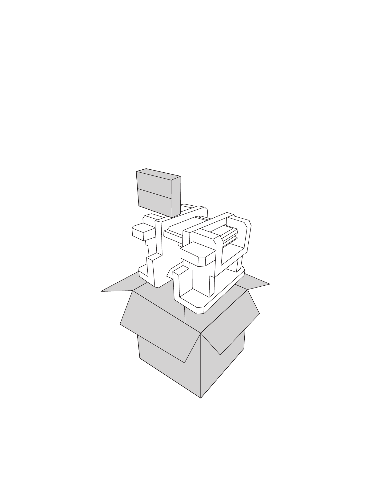
Unpacking the machine
It is a good idea to save the packaging materials and shipping box in case that machine needs to be returned
for service. Please un-pack and re-pack the machine terminal as shown in Figure 1.1.
Figure 1.1 Unpacking the
machine
2 CHAPTER 1 GETTING STARTED
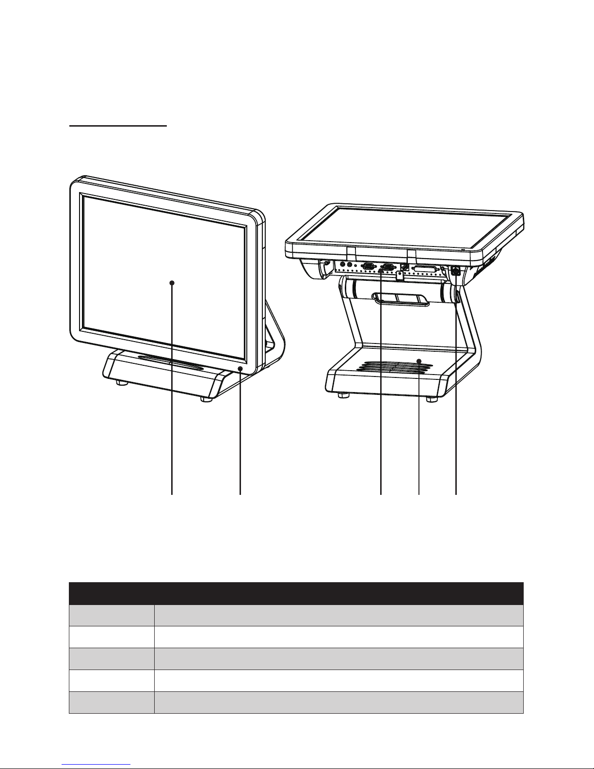
Identifying components
This section describes the parts and connectors on the machine.
1 2
Figure 1.2 Front-right view
Component Description
1 15-inch TFT LCD
2 LED Power Indicator
3 IO Panel
4 HDD Compartment
5 Power Button
3 54
Front-right view
3
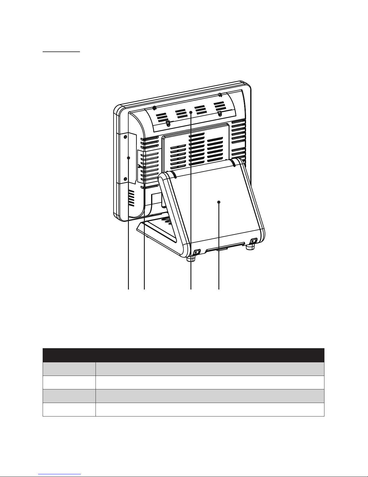
Rear view
1 2 3 4
Figure 1.3 Rear view
Component Description
1 MSR (optional) Slot
2 HDD Compartment (for wall mounting)
3 VFD Customer Display (optional) Slot
4 Cable Compartment
4 CHAPTER 1 GETTING STARTED
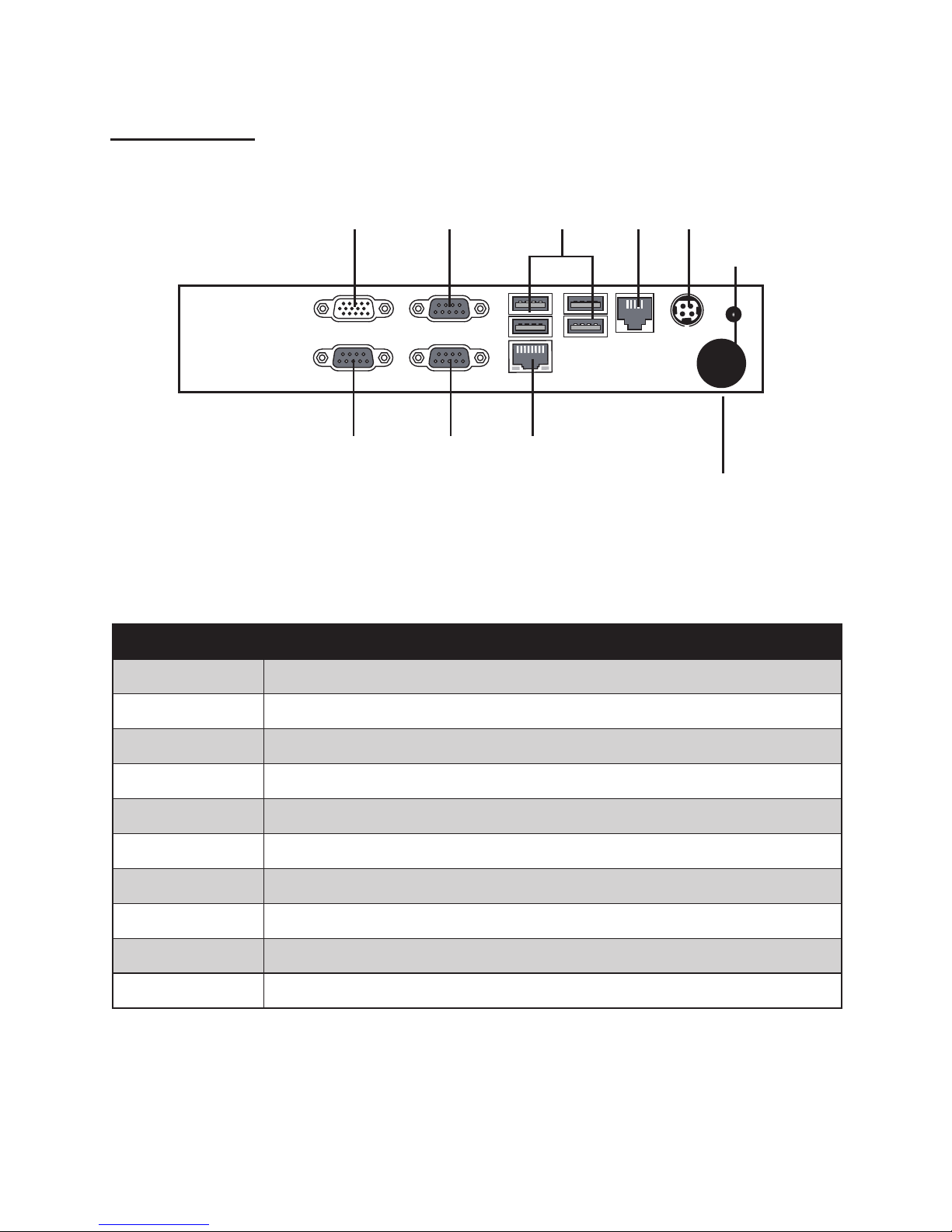
I/O connectors
Connector Description
1 VGA port
2 COM 1 port
3 USB ports
4 RJ11 cash drawer port
5 DC 12V input connector
6 DC 12V output connector
7 COM 3 port
8 COM 2 port
9 LAN jack
10 SATA cable hole
521 3 4
6
7 8 9
10
Figure 1.4 SP-600-A I/O connectors
5
15
69
Connector pin dene
This section describes the connectors pin dene.
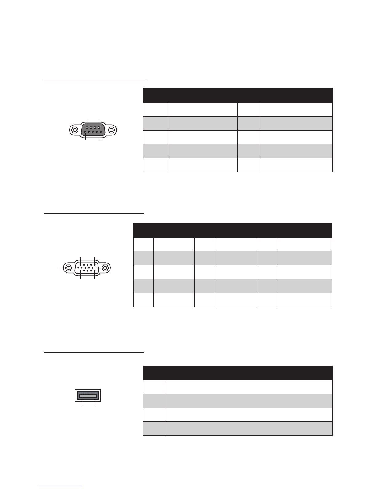
COM connector pin dene
VGA connector pin dene
USB connector pin dene
Pin Signal Pin Signal
1 DCD 6 DSR
2 SIN 7 RTS
3 SOUT 8 CTS
4 DTR 9 RI
5 GND
1 5
6
10
11 15
Pin Signal Pin Signal Pin Signal
1 Red 6 AGND 11 N/A
2 Green 7 AGND 12 DDC DAT
3 Blue 8 AGND 13 Horizontal Sync
4 N/A 9 N/A 14 Vertical Sync
5 GND 10 GND 15 DDC CLK
14
Pin Signal
1 USB Vcc
2 USB -
3 USB +
4 USB GND

6 CHAPTER 1 GETTING STARTED
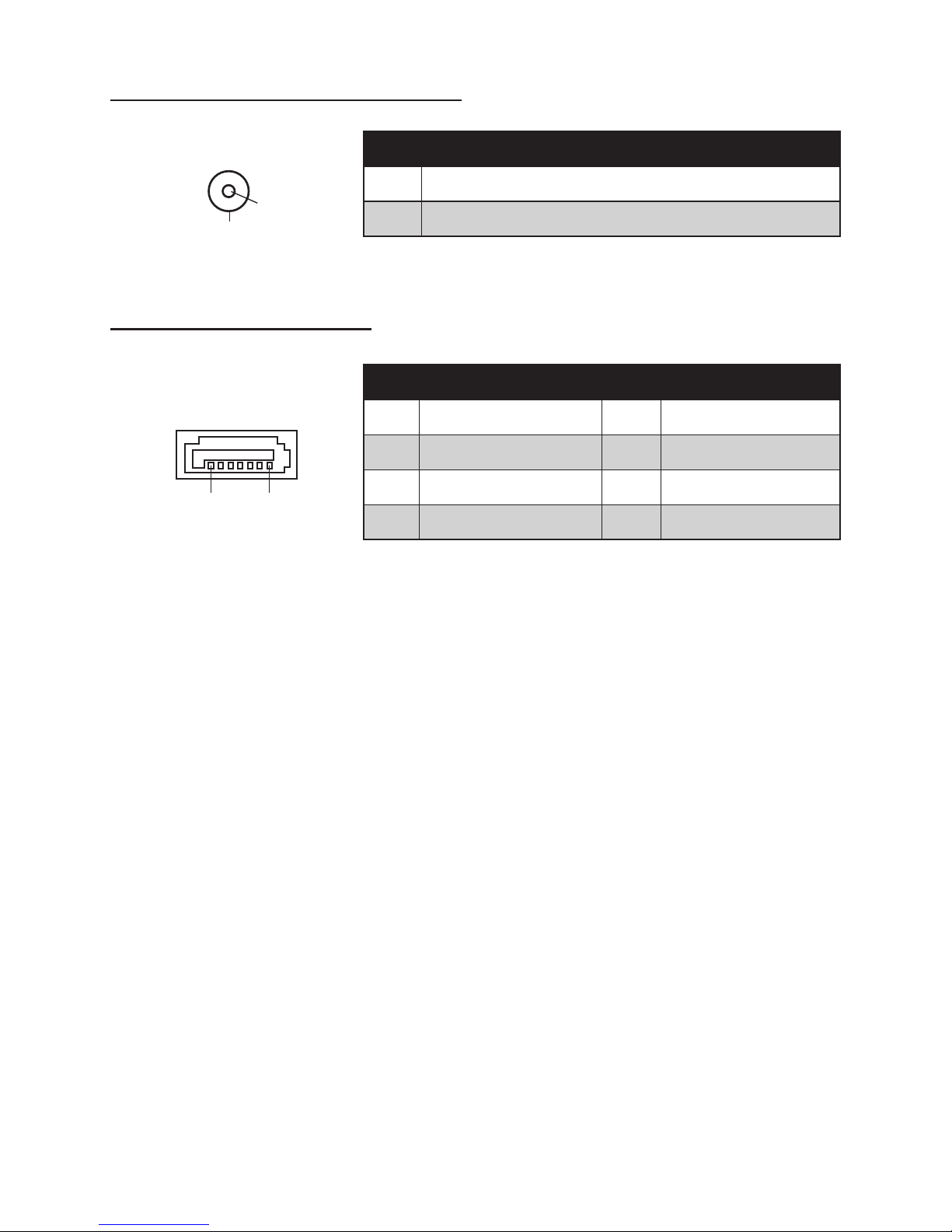
RJ-11 Cash Drawer connector pin dene
LAN connector pin dene
1 6
1 8
Pin Signal
1 CASEOPEN2
2 CASH1
3 CASEOPEN1
4 24V
5 CASH2
6 GND
Pin Signal Pin Signal
1 TXA+ 5 TXC-
2 TXA- 6 TXB-
3 TXB+ 7 TXD+
4 TXC+ 8 TXD-
DC 12V input connector pin dene
1
2
3
4
5
Pin Signal
1 V+
2 V+
3 GND
4 GND
5 GND
7
DC 12V output connector pin dene
SATA connector pin dene
Pin Signal
1 +12V
2 GND
7 1
Pin Signal Pin Signal
1 GND 5 SATA_RX-
2 SATA_TX+ 6 SATA_RX+
3 SATA_TX- 7 GND
4 GND
1
2

8 CHAPTER 1 GETTING STARTED

9
CHAPTER 2
BIOS SETUP
The primary function of the BIOS (Basic Input and Output System) is to identify and initiate component
hardware. The BIOS parameters are stored in non-volatile BIOS memory (CMOS). CMOS contents don’t get
erased when the computer is turned off. The following topics are described in this chapter.
• About the Setup Utility on page 9
• Main Screen on page 12
• Advanced Settings on page 13
• Chipset Settings on page 24
• Boot Settings on page 28
• Security Settings on page 29
• Save & Exit on page 30
About the Setup Utility
The BIOS Setup Utility enables you to congure the following items:
• Hard drives, diskette drives, and peripherals
• Video display type and display options
• Password protection from unauthorized use
• Power management features
This Setup Utility should be used for the following:
• When changing the system conguration
• When a conguration error is detected and you are prompted to make changes to the Setup Utility
• When trying to resolve IRQ conicts
• When making changes to the Power Management conguration
• When changing the User or Supervisor password
10 CHAPTER 2 BIOS SETUP
Entering the Setup Utility
When you power on the system, BIOS enters the Power-On Self Test (POST) routines. POST is a series of
built-in diagnostics performed by the BIOS. After the POST routines are completed, the following message
appears:
Press DEL to run Setup
Press the delete key <Delete> to access the BIOS Setup Utility:
BIOS navigation keys
The BIOS navigation keys are listed below.
Key Function
← → Moves between the available menus
↑ ↓ Moves the cursor between the displayed parameters
+ – Modies the selected eld’s values
Enter Go to sub screen
F1 Displays a general help screen
F2 Loads the previous values
F9 Loads the default congurations
F10 Saves the current conguration and exits Setup
Esc Exits the current screen
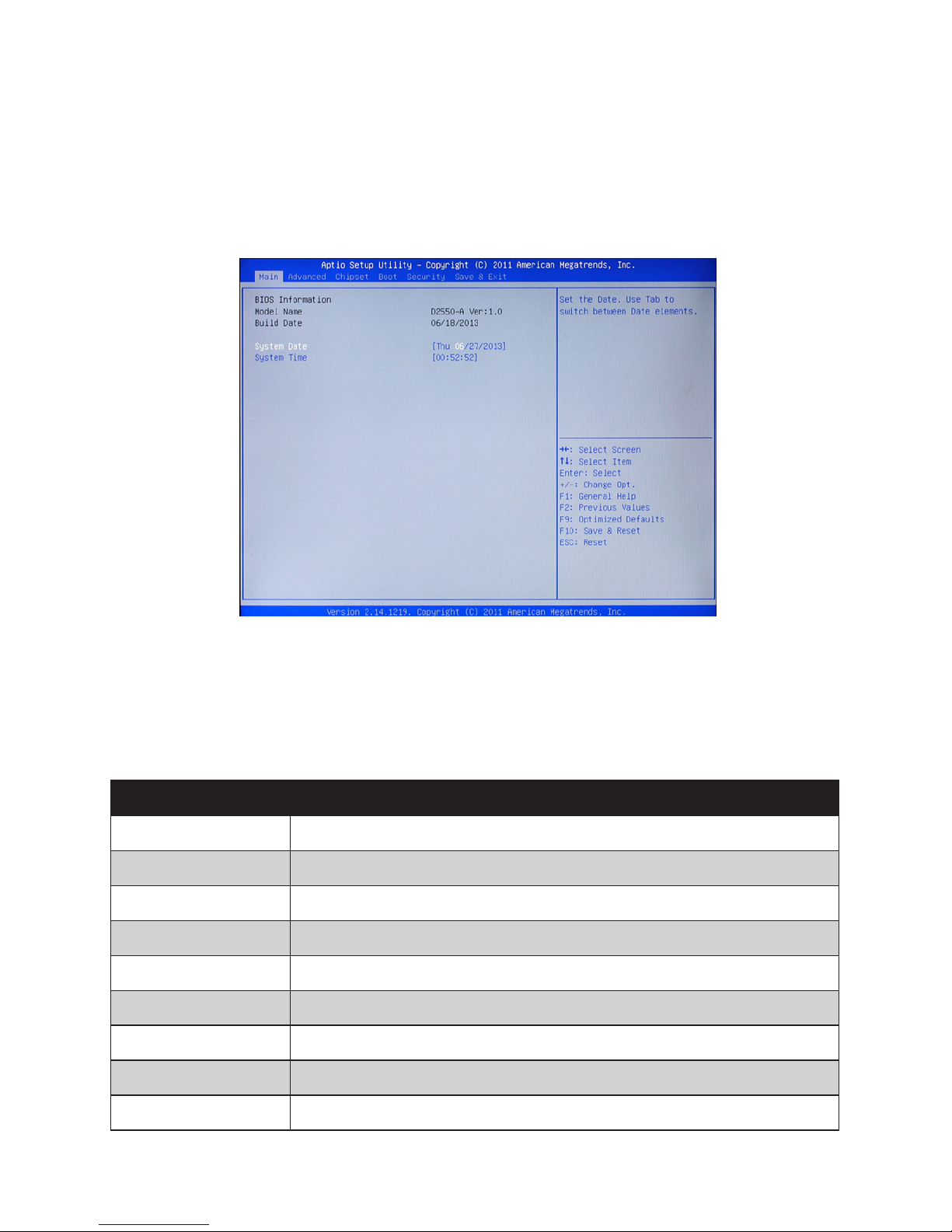
Figure 3.1 Main BIOS screen

11
Using BIOS
When you start the Setup Utility, the main screen appears. The main screen of the Setup Utility displays a list
of the options that are available. A highlight indicates which option is currently selected. Use the cursor arrow
keys to move the highlight to other options. When an option is highlighted, execute the option by pressing
<Enter>.
Some options lead to pop-up dialog boxes that prompt you to verify that you wish to execute that option.
Other options lead to dialog boxes that prompt you for information.
Some options (marked with a triangle ►) lead to sub screens that enable you to change the values for the op-
tion. Use the cursor arrow keys to scroll through the items in the sub screen.
12 CHAPTER 2 BIOS SETUP
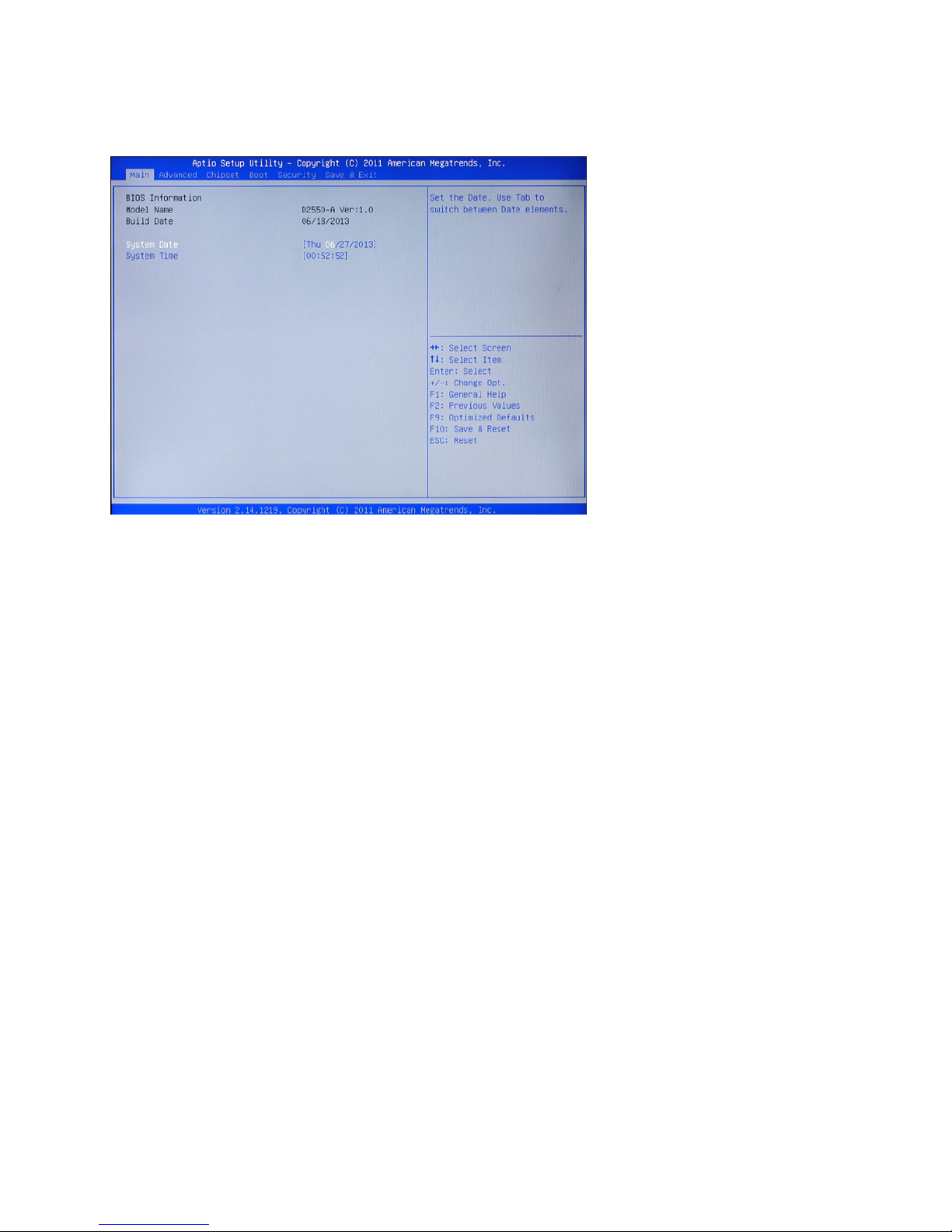
Main Screen
This screen includes System BIOS Information, Processor, System memory and displays the System Time
and System Date.
System Overview
This screen displays System BIOS Information, Processor, System memory, System Time and System Date.
System Time/ System Date
The System Time and System Date items show the current date and time held by the machine.
To set the time and date use the Tab key to move from eld to eld. Simply type the new number required.
If you are running a Windows OS, these items are automatically updated whenever you make changes to the
Windows Time and Date Properties utility.
Figure 3.2 Main Screen

13
Advanced Settings
This setup screen includes sub-menus for APCI Conguration, CPU Conguration, SATA Conguration, USB
Congurations, Super IO Congurations and Hardware Health Conguration.
Figure 3.3 Advanced
Settings Screen
14 CHAPTER 2 BIOS SETUP
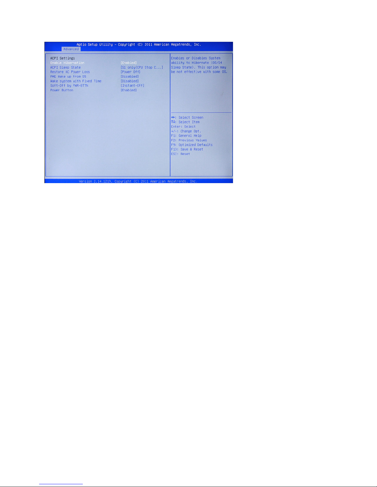
ACPI Settings
Figure 3.4 ACPI Settings sub-menu
Enable Hibernation
This item allows user to enable or disable the hibernation feature for OS. This option may be not effective
with some OS.
ACPI Sleep State
Use this item to dene how the system suspends. In the default, S1 only (CPU Stop Clock), the suspend mode
is equivalent to a software power down. If you select S3 only (Suspend To RAM), the suspend mode is a
suspend to RAM - the system shuts down with the exception of a refresh current to the system memory.
Restore AC Power Loss
This item sets the system status after restore on AC power loss.
PME Wake up from S5
This feature allows the system wakeup on PME (Power Management Event).
Wake system with Fixed Time
This function is for setting the Date and Time for your computer to boot up. When enabled, more options will
appear for you to specic the Date and Time.
Soft-Off by PWR-BTTN
Under ACPI (Advanced Conguration and Power management Interface) you can create a software power
down. In a software power down, the system can be resumed by Wake Up Alarms. This item lets you install
a software power down that is controlled by the normal power button on your system. If the item is set to
Instant-Off, then the power button causes a software power down. If the item is set to Delay 4 Sec. then you
have to hold the power button down for four seconds to cause a software power down.
15
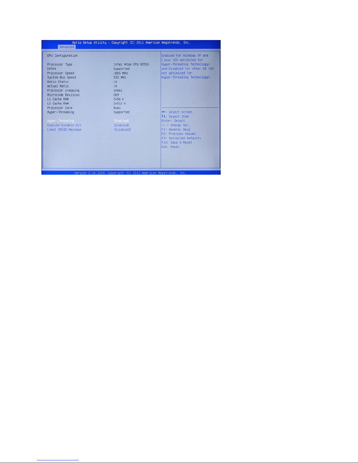
CPU Conguration
Figure 3.5 CPU Conguration sub-menu
Hyper Threading
This feature allows a single processor to execute two or more separate threads concurrently. When hyperthreading is enabled, multi-threaded software applications can execute their threads in parallel, thereby
improving their performance.
Execute-Disable Bit Capability
This feature is used to protect certain system memory data regions from insertion and execution of potentially
harmful code.
Limit CPUID Maximum
When enabled, the processor will limit the maximum CPUID input value to 03h when queried, even if the
processor supports a higher CPUID input value. When disabled, the processor will return the actual maximum
CPUID input value of the processor when queried.

16 CHAPTER 2 BIOS SETUP
SATA Conguration
SATA Controller
Use this item to enable or disable the on-chip SATA controller. The default setting is Enabled.
SATA Mode Selection
This item is used to congure SATA mode. The default setting is IDE.
SMART Self Test
This item is used to enable monitoring of hard disks that support the S.M.A.R.T. (Self-Monitoring And Reporting Technology) feature, which can allow the hard disk to report, under some circumstances, impending
failures of the hard disk.
Figure 3.6 SATA Con-
guration sub-menu
 Loading...