

Partner SP-550 Service Manual

POS Terminal
SP-550
Service Manual

2
Regulatory Notices
WARNING
This is Class A Product. In domestic environment this product may cause radio interference in which
case the user may be required to take adequate measures.
警告使用者
這是甲類的資訊產品,在居住的環境中使用時,可能會造成射頻干擾,在這種情況下,使用者會被要
求採取某些適當的對策。
FCC Statement
This device has been tested and found to comply with the limits for a Class A digital device,
pursuant to part 15 of the FCC Rules, these limits are designed to provide reasonable protection
against harmful interference when the device is operated in a commercial environment. This device
generates, uses and can radiate frequency energy and, if not installed and used in accordance with
this manual, may cause harmful interference to radio communications. Operation of this device in
a residential area is likely to cause harmful interference in which case the user will be required to
correct the interference at his/her own expense.
FCC WARNING
Changes or modications not expressly approved by the party responsible for compliance could void
the user’s authority to operate the device.
Best Management Practice (BMP) for Perchlorate Materials in California
States
This device includes perchlorate in the lithium battery.
Perchlorate material-special handling may apply when handling this device.
For detail, refer to http://www.dtsc.ca.gov/hazardouswaste/perchlorate.
Vermont Mercury Management Rules
LCD display lamps contain mercury. Dispose of them properly.
CE Mark
This device complies with the requirements of the EEC directive 2004/108/EC with regard to
“Electromagnetic compatibility” and 2006/95/EC with regard to “Low Voltage Directive”.

3
Legislation and WEEE Symbol
2002/96/EC Waste Electrical and Electronic Equipment Directive on the treatment, collection,
recycling and disposal of electric and electronic devices and their components.
The crossed-out wheeled bin symbol on the device means that it should not be disposed of with
other waste at the end of its working life. Instead, the device should be delivered to a waste
collection center for activation of the treatment, collection, recycling and disposal procedure.
To prevent possible harm to the environment or human health from uncontrolled waste disposal,
please separate this device from other types of waste and recycle it responsibly to promote the
sustainable reuse of material resources.
Business users should contact their supplier and check the terms and conditions of the purchase
contract regarding its disposal.
It should not be mixed with other commercial waste for disposal.
WARNING
The system uses a 3V CR2032 battery mounted on the mainboard to keep time. There is a risk of
explosion if the wrong battery type is used when replacing. Dispose of used batteries according to
local ordinance regulations.
4
Safety Information
Computer components and electronic circuit boards can be damaged by discharges of static
electricity. Working on computers that are still connected to a power supply can be extremely
dangerous. Follow these guidelines to avoid damage to the computer or injury to yourself.
• Always disconnect the unit from the power outlet.
• Leave all components inside the static-proof packaging that they ship with until they are ready
for installation.
• After replacing optional devices, make sure all screws, springs, or other small parts are in place
and are not left loose inside the case. Metallic parts or metal akes can cause electrical shorts.
CAUTION
Only qualied personnel should perform repairs. Damage due to unauthorized
servicing is not covered by the warranty.
CAUTION
Under no circumstances touch the inverter while power is connected to the
machine. Always disconnect the AC power cord before attempting any service.
CAUTION
If the LCD breaks and uid gets onto your hands or into your eyes, immediately
wash with water and seek medical attention.
CAUTION
To prevent static damage to components, wear a grounded wrist strap.
Alternatively, discharge any static electricity by touching the bare metal chassis of
the unit case, or the bare metal body of any other grounded appliance.
CAUTION
Hold electronic circuit boards by the edges only. Do not touch the components on
the board unless it is necessary to do so. Do not ex or stress the circuit board. Do
not hold components such as a processor by its pins; hold it by the edges.

5
Contact Information
Partner Tech Corporation
10F., No.233-2, Baoqiao Rd., Xindian Dist., New Taipei City 231, Taiwan (R.O.C.)
http://www.partner.com.tw/

6
Copyright and Trademark
Copyright
This publication, including all photographs, illustrations and software, is protected under
international copyright laws, with all rights reserved. Neither this manual, nor any of the material
contained herein, may be reproduced without written consent of the author.
Disclaimer
The information in this document is subject to change without notice. The manufacturer makes
no representations or warranties with respect to the contents hereof and specically disclaims any
implied warranties of merchantability or tness for any particular purpose.
The manufacturer reserves the right to revise this publication and to make changes from time to
time in the content hereof without obligation of the manufacturer to notify any person of such
revision or changes.
Trademark Recognition
All product names used in this manual are the properties of their respective owners and are
acknowledged.
About this manual
The service manual provides service information. This manual is designed to help train service
personnel to locate and x failing parts on the device.
This manual consists of the following sections:
Chapter 1 Getting Started: This section covers unpacking and checking the package contents,
and identifying components.
Chapter 2 BIOS Setup Utility: The BIOS chapter provides information on navigating and
changing settings in the BIOS Setup Utility.
Chapter 3 Installing Drivers and Software: This chapter provides information for installing
drivers.
Chapter 4 Locating the Problem: Refer to this chapter to locate the failing part or cause of the
problem that requires servicing.
Chapter 5 Replacing Field Replaceable Units (FRUs): This chapter provides drawings and
instructions to replace all FRUs.
Appendix: The appendix includes an exploded diagram of the machine and the parts list and order
number for each part.
Manual Release Date
2016/04/21

7
Contents
Regulatory Notices ............................................................................................................ 2
Safety Information ............................................................................................................ 4
Contact Information .......................................................................................................... 5
Copyright and Trademark ................................................................................................. 6
About this manual ............................................................................................................ 6
Chapter 1 Getting Started ................................................................................................9
Unpacking ........................................................................................................................ 9
Identifying Components .................................................................................................. 10
Connector Pin Define ....................................................................................................... 13
Mainboard Jumper .......................................................................................................... 16
Mainboard Connectors ..................................................................................................... 18
Chapter 2 BIOS Setup ................................................................................................... 19
About the BIOS Setup Utility ........................................................................................... 19
Entering the Setup Utility ................................................................................................ 20
Using BIOS .................................................................................................................... 20
BIOS Navigation Keys ...................................................................................................... 20
Main Screen .................................................................................................................... 21
Advanced Settings ........................................................................................................... 22
Chipset Settings .............................................................................................................. 29
Security Settings ............................................................................................................. 33
Boot Settings .................................................................................................................. 34
Save & Exit ..................................................................................................................... 35
Chapter 3 Installing Drivers and Software ................................................................... 37
Driver Installation ........................................................................................................... 37
Intel Chipset Driver ......................................................................................................... 38
Intel Chipset Graphics Driver ............................................................................................ 40
LAN Driver ...................................................................................................................... 42
Chapter 4 Locating the Problem .................................................................................... 45
General Checkout Guidelines ............................................................................................ 45
Cash Drawer Checkout .................................................................................................... 45
LCD Symptoms ............................................................................................................... 46
Touch Screen Symptoms .................................................................................................. 47
Power Symptoms ............................................................................................................ 47

8
Network Symptoms ......................................................................................................... 47
USB Symptoms ............................................................................................................... 48
Peripheral-Device Symptoms ............................................................................................ 48
Boot Symptoms .............................................................................................................. 48
Chapter 5 Replacing Field Replaceable Units (FRUs) .................................................... 49
MSR ............................................................................................................................... 50
Customer Display ............................................................................................................ 50
Hard Disk Drive ............................................................................................................... 51
Panel.............................................................................................................................. 52
Rear Hard Drive Compartment Cover ................................................................................ 53
Panel Back Cover ............................................................................................................ 54
EMI Shield ...................................................................................................................... 54
Speaker .......................................................................................................................... 55
Power Button .................................................................................................................. 55
Memory .......................................................................................................................... 55
Battery ........................................................................................................................... 56
I/O Shield ....................................................................................................................... 56
Mainboard ...................................................................................................................... 57
Heatsink ......................................................................................................................... 57
Touch Panel, LCD Panel ................................................................................................... 58
Appendix A Part List and Specification ......................................................................... 59
Exploded Diagram ........................................................................................................... 59
Specifications .................................................................................................................. 61
1
9
Getting Started
This chapter describes how to unpack and identifying components on the device.
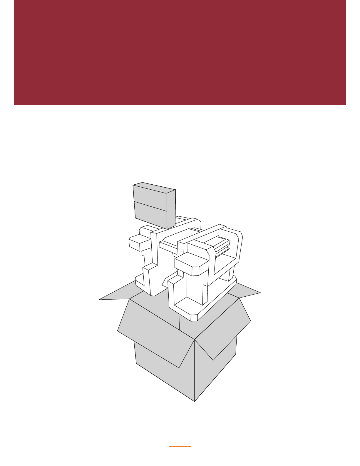
Unpacking
It is a good idea to save the packaging materials and shipping box in case that machine needs to
be returned for service. Please un-pack and re-pack the machine terminal as shown below.
10
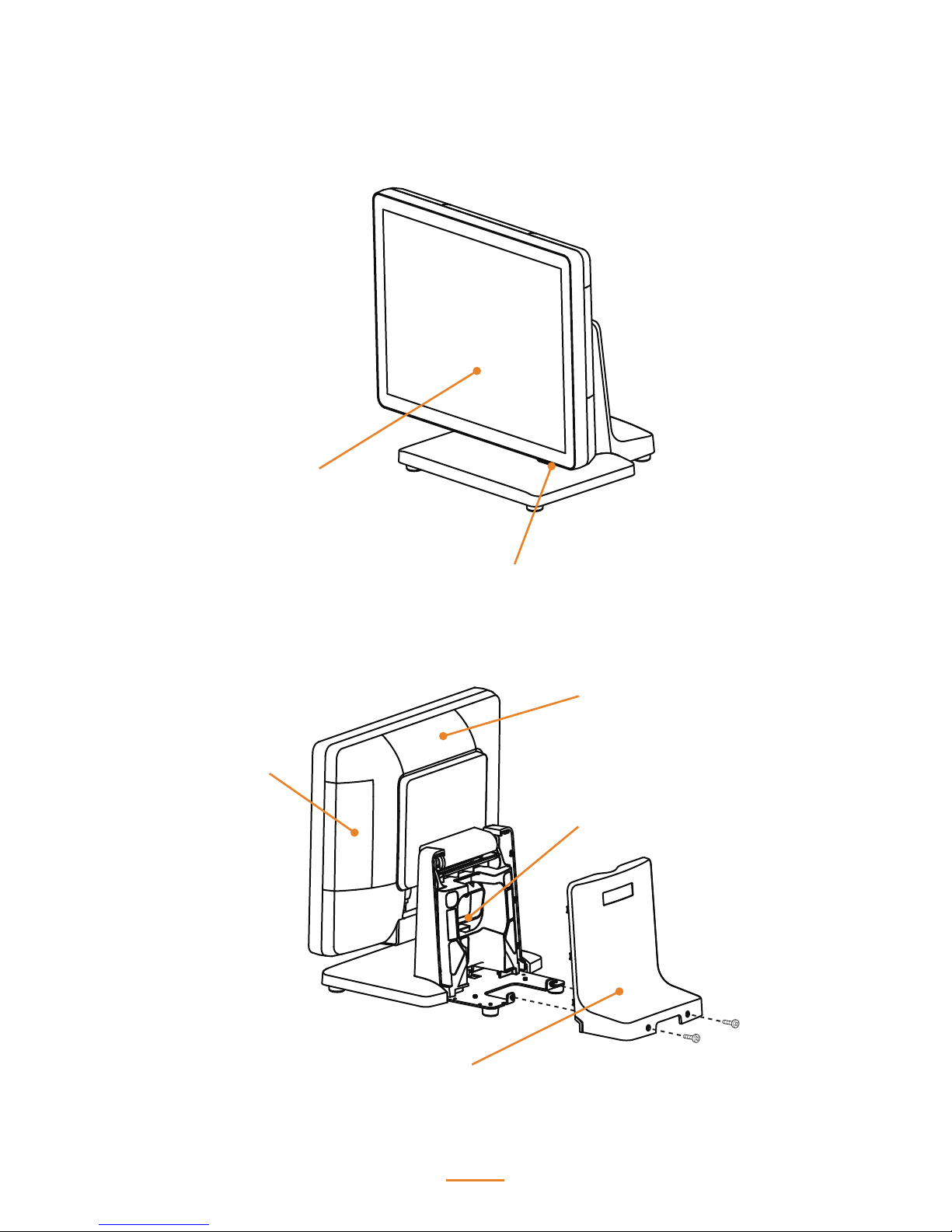
Identifying Components
This section describes the parts and connectors on the machine.
LED Power Indicator
15-inch TFT LCD
MSR (optional) Slot
VFD Customer Display
(optional) Slot
Cable Compartment
Cable Compartment Cover
11
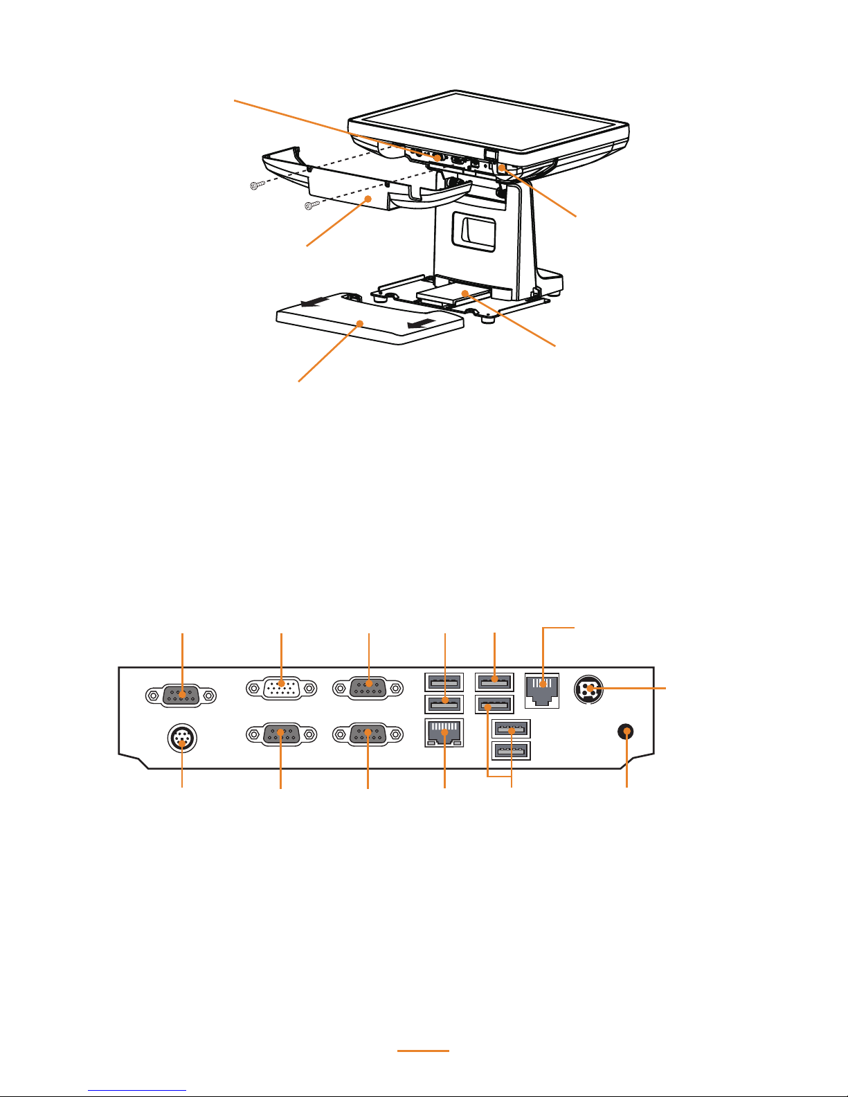
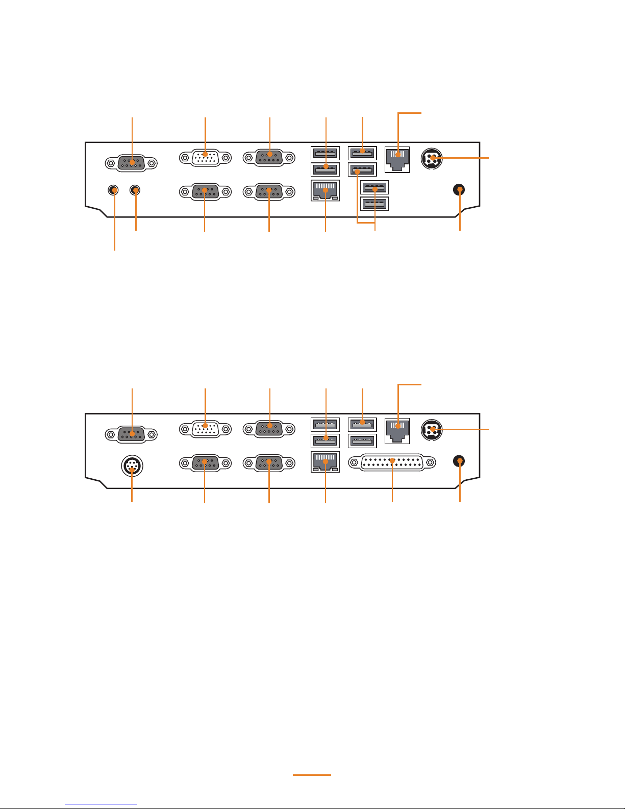
I/O Panel
I/O Cover
HDD Compartment Cover
HDD
Power Button
I/O Connectors
DC12V-In
DC12V-Out
COM2
COM3PS/2 KB
COM4
LAN
RJ-11
Cash drawer port
VGA COM1 USB 3.0USB 2.0
USB 2.0
12
DC12V-In
DC12V-In
DC12V-Out
DC12V-Out
COM2
COM2
COM3
COM3
Line Out
MIC In
PS/2 KB
COM4
COM4
LAN
LAN
RJ-11
Cash drawer port
RJ-11
Cash drawer port
VGA
VGA
COM1
COM1
USB 3.0
USB 3.0
USB 2.0
USB 2.0
USB 2.0
LPT
13
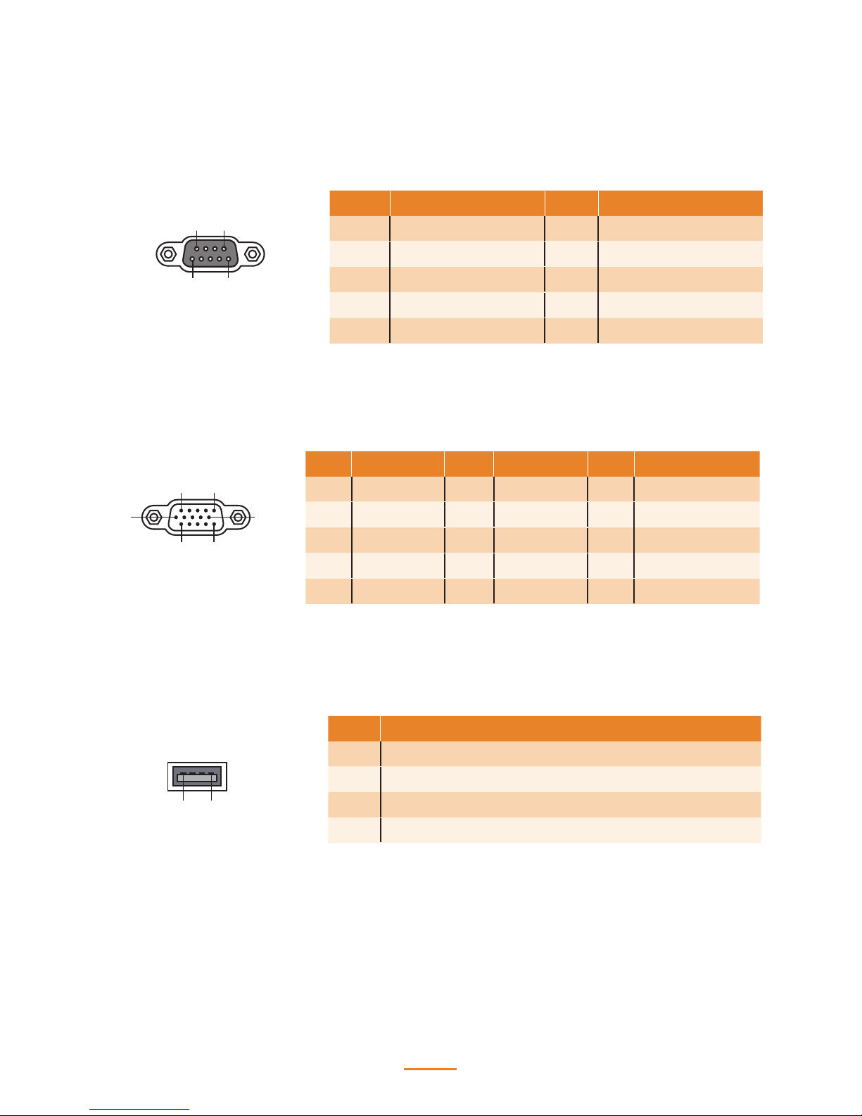
Connector Pin Dene
This section describes the connectors pin dene.
VGA Connector Pin Dene
USB 2.0 Connector Pin Dene
1 5
6
10
11 15
Pin Signal Pin Signal Pin Signal
1 Red 6 AGND 11 N/A
2 Green 7 AGND 12 DDC DAT
3 Blue 8 AGND 13 Horizontal Sync
4 N/A 9 N/A 14 Vertical Sync
5 GND 10 GND 15 DDC CLK
14
Pin Signal
1 USB Vcc
2 USB -
3 USB +
4 USB GND
15
69
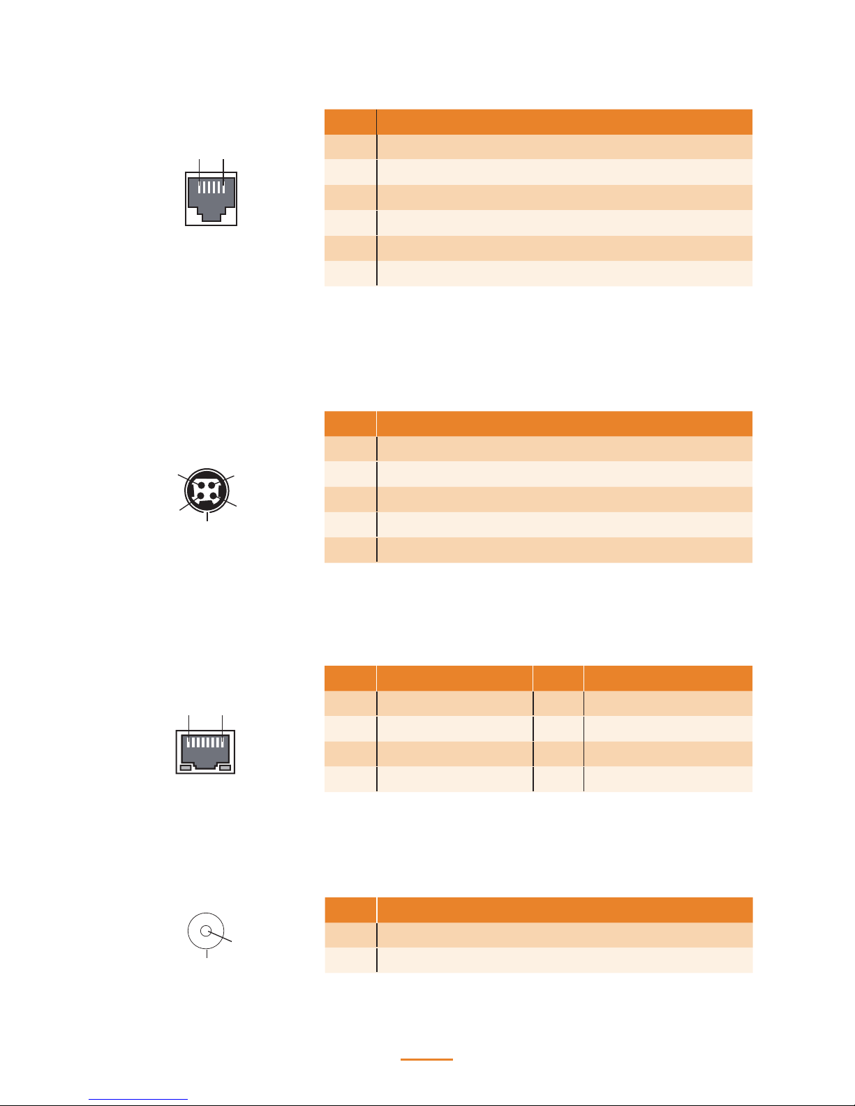
COM Connector Pin Dene
Pin Signal Pin Signal
1 DCD 6 DSR
2 SIN 7 RTS
3 SOUT 8 CTS
4 DTR 9 RI*
5 GND
*Can be selected for 5V or 9V via jumpers.
14
RJ-11 Cash Drawer Connector Pin Dene
LAN Connector Pin Dene
1 6
1 8
Pin Signal
1 CASEOPEN2
2 CASH1
3 CASEOPEN1
4 24V
5 CASH2
6 GND
*Voltage is selected via JP1
Pin Signal Pin Signal
1 TXA+ 5 TXC-
2 TXA- 6 TXB-
3 TXB+ 7 TXD+
4 TXC+ 8 TXD-
DC 12V Input Connector Pin Dene
1
2
3
4
5
Pin Signal
1 V+
2 V+
3 GND
4 GND
5 GND
DC 12V Output Connector Pin Dene
Pin Signal
1 +12V
2 GND
1
2
15
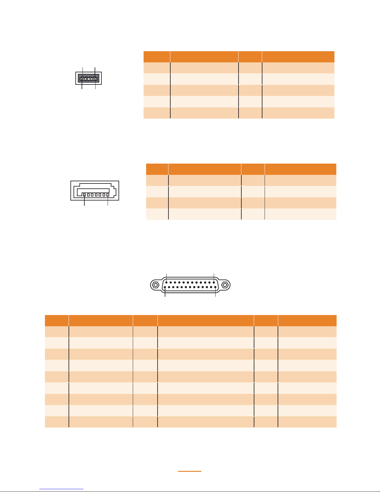
SATA Connector Pin Dene
7 1
Pin Signal Pin Signal
1 GND 5 SATA_RX-
2 SATA_TX+ 6 SATA_RX+
3 SATA_TX- 7 GND
4 GND
USB 3.0 Connector Pin Dene
9
1
5
4
Pin Signal Pin Signal
1 USB Vcc 5 StdA_SSRX-
2 USB - 6 StdA_SSRX+
3 USB + 7 GND
4 USB GND 8 StdA_SSTX-
9 StdA_SSTX+
Parallel Connector Pin Dene
1
13
14
25
Pin Signal Pin Signal Pin Signal
1 Strob# 10 Acknowledge# 19 GND
2 Data 0 11 Busy 20 GND
3 Data 1 12 Paper Empty# 21 GND
4 Data 2 13 Printer Select 22 GND
5 Data 3 14 Auto Form Feed# 23 GND
6 Data 4 15 Error# 24 GND
7 Data 5 16 Initialize# 25 GND
8 Data 6 17 Printer Select In#
9 Data 7 18 GND
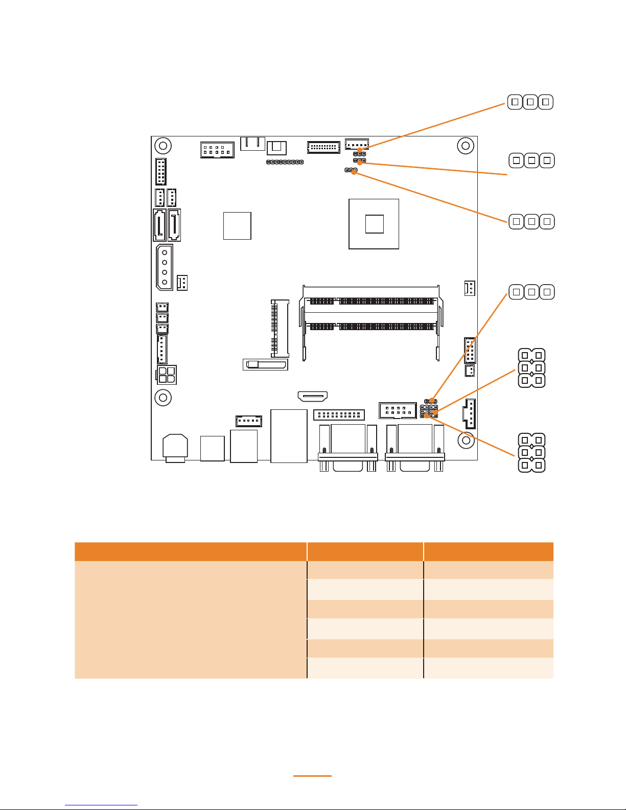
16
Mainboard Jumper
JLV2
JLV1
JCMOS
JT1
JP4
JP3
Jumper Setting Description
JLV1
(LVDS Backlight Power Select Jumper)
1-2 Closed +5V
2-3 Closed (Default) +12V
JLV2
(LVDS VDD Select Jumper)
1-2 Closed (Default) +3.3V
2-3 Closed +5V
JCMOS
(Clear CMOS Jumper)
1-2 Close (Default) Keep Data
2-3 Close Clear CMOS
1
1
1
1
1
1
2
2
5
5
6
6

17
Jumper Setting Description
JP3
(COM3 Power Select Jumper)
1-2 Close COM3 Pin 9: 5V
3-4 Close (Default) COM3 Pin 9: RING
5-6 Close COM3 Pin 9: 12V
JP4
(COM4 Power Select Jumper)
1-2 Close COM4 Pin 9: 5V
3-4 Close (Default) COM4 Pin 9: RING
5-6 Close COM4 Pin 9: 12V
JT1
(Touch Panel USB or PS/2 Interface
Select Jumper)
1-2 Close PS/2 Interface
2-3 Close (Default) USB Interface
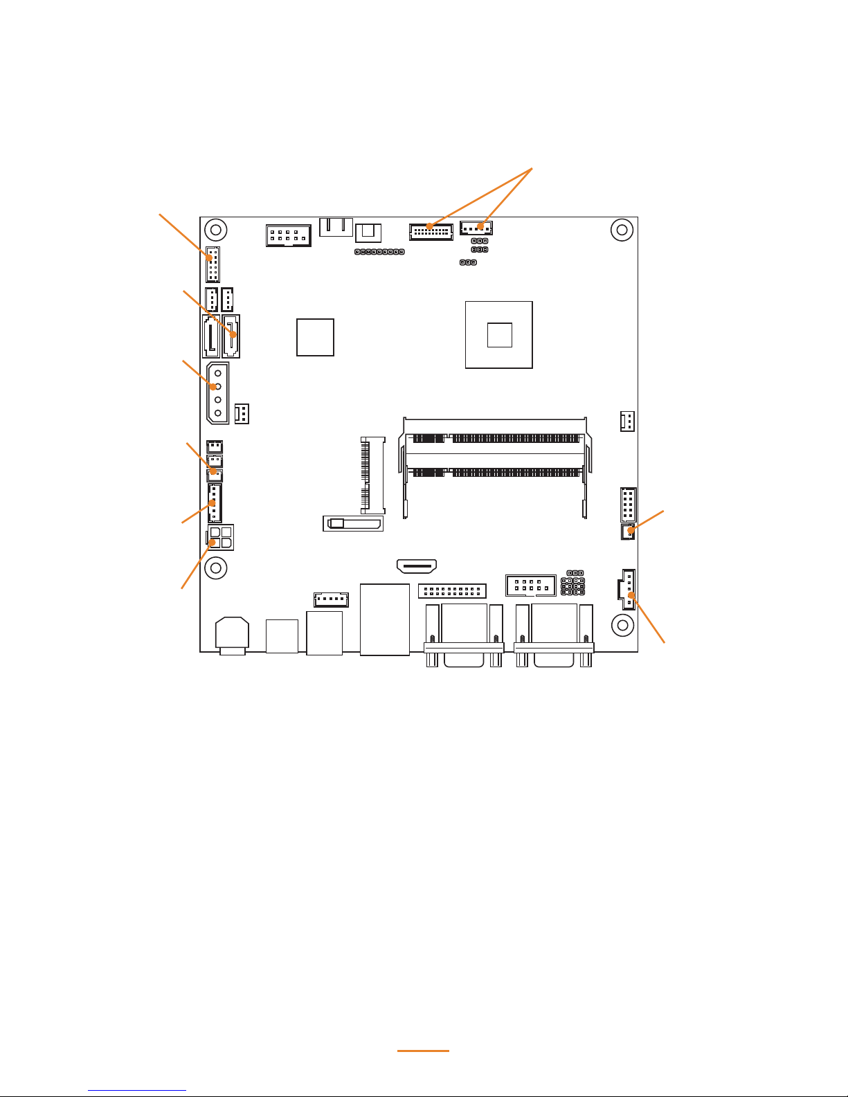
18
Mainboard Connectors
connector to
LCD panel
connector to
MSR
connector to
SATA HDD
connector to
HDD power
connector to
speaker
connector to
touch panel
connector to
power LED
connector to
power button
connector to
power jack

2
19
BIOS Setup
The primary function of the BIOS (Basic Input and Output System) is to identify and initiate
component hardware. The BIOS parameters are stored in non-volatile BIOS memory (CMOS).
CMOS contents don’t get erased when the computer is turned o.
About the BIOS Setup Utility
The BIOS Setup Utility enables you to congure the following items:
• Hard drives, diskette drives, and peripherals
• Video display type and display options
• Password protection from unauthorized use
• Power management features
This Setup Utility should be used for the following:
• When changing the system conguration
• When a conguration error is detected and you are prompted to make changes to the Setup
Utility
• When trying to resolve IRQ conicts
• When making changes to the Power Management conguration
• When changing the User or Supervisor password
 Loading...