

Page 1
POS Terminal
SP-1000-C
Service Manual
Page 2

Page 3

i
Copyright
This publication, including all photographs, illustrations and software, is protected under international
copyright laws, with all rights reserved. Neither this manual, nor any of the material contained herein, may be
reproduced without written consent of the author.
Disclaimer
The information in this document is subject to change without notice. The manufacturer makes no representa-
tions or warranties with respect to the contents hereof and specically disclaims any implied warranties of
merchantability or tness for any particular purpose. The manufacturer reserves the right to revise this publi-
cation and to make changes from time to time in the content hereof without obligation of the manufacturer to
notify any person of such revision or changes.
Trademark recognition
All product names used in this manual are the properties of their respective owners and are acknowledged.
Federal Communications Commission (FCC)
This equipment has been tested and found to comply with the limits for a Class A digital device, pursuant to
Part 15 of the FCC Rules. These limits are designed to provide reasonable protection against harmful interference in a residential installation. This equipment generates, uses, and can radiate radio frequency energy
and, if not installed and used in accordance with the instructions, may cause harmful interference to radio
communications. However, there is no guarantee that interference will not occur in a particular installation. If
this equipment does cause harmful interference to radio or television reception, which can be determined by
turning the equipment off and on, the user is encouraged to try to correct the interference by one or more of
the following measures:
Reorient or relocate the receiving antenna.
Increase the separation between the equipment and the receiver.
Connect the equipment onto an outlet on a circuit different from that to which the receiver is connected.
Consult the dealer or an experienced radio/TV technician for help.
Shielded interconnect cables and a shielded AC power cable must be employed with this equipment to ensure
compliance with the pertinent RF emission limits governing this device. Changes or modications not expressly approved by the system’s manufacturer could void the user’s authority to operate the equipment.
Declaration of conformity
This device complies with part 15 of the FCC rules. Operation is subject to the following conditions:
This device may not cause harmful interference, and
This device must accept any interference received, including interference that may cause undesired operation.
Page 4

ii
About this manual
The service manual provides service information for the SP-1000-C. This manual is designed to help train
service personnel to locate and x failing parts on the machine.
This manual consists of the following sections:
Chapter 1 Getting Started:
This section covers unpacking and checking the package contents, and identifying components.
Chapter 2 BIOS Setup Utility:
The BIOS chapter provides information on navigating and changing settings in the BIOS Setup
Utility.
Chapter 3 Installing Drivers and Software:
This chapter provides information for installing drivers.
Chapter 4 Locating the Problem:
Refer to this chapter to locate the failing part or cause of the problem that requires servicing.
Chapter 5 Replacing Field Replaceable Units (FRUs):
This chapter provides drawings and instructions to replace all FRUs.
Appendix: Optional Components, Exploded Diagram, and Parts List:
The appendix includes an exploded diagram of the machine and the parts list and order number for
each part.
Safety information
Before servicing the machine, read the safety information under “Safety and precautions” on page 51.
Revision history
Version 1.0, June 2011
Page 5

iii
TABLE OF CONTENTS
CHAPTER 1 GETTING STARTED ................................................ 1
Unpacking the machine .................................................................................1
Identifying components .................................................................................2
CHAPTER 2 BIOS SETUP ............................................................ 5
About the Setup Utility ...................................................................................5
Entering the Setup Utility ..........................................................................6
BIOS navigation keys ................................................................................6
Using BIOS ...............................................................................................7
Main Screen ...................................................................................................8
SATA Port 1/ 2 ............................................................................................9
Intel Settings ................................................................................................10
CPU Control Sub-Menu ...........................................................................11
PCH Control Sub-Menu ...........................................................................12
PCI Express Control Sub-Menu ...............................................................13
LPC Control Sub-Menu ............................................................................14
SIO Control Sub-Menu ............................................................................15
H/W Monitor Sub-Menu ...........................................................................17
AMT Sub-Menu ........................................................................................18
Keyboard Feature Sub-Menu ..................................................................19
Security Settings ..........................................................................................20
Boot Settings ................................................................................................21
Exit Menu .....................................................................................................22
CHAPTER 3 INSTALLING DRIVERS AND SOFTWARE ............ 25
Driver auto installation..................................................................................25
Intel Chipset Driver.......................................................................................26
Intel Management Engine Driver..................................................................28
Intel Chipset Graphics Driver .......................................................................30
HD Audio driver ............................................................................................32
LAN Driver ....................................................................................................33
Touch Screen Driver.....................................................................................36
Calibrating the touchscreen .....................................................................39
CHAPTER 4 LOCATING THE PROBLEM .................................. 41
General checkout guidelines ........................................................................41
Cash drawer checkout .................................................................................41
Page 6

iv
LCD symptoms .............................................................................................42
Touch screen symptoms ..............................................................................43
Power symptoms..........................................................................................43
Network symptoms .......................................................................................43
USB symptoms ............................................................................................44
Peripheral-device symptoms ........................................................................44
Boot symptoms ............................................................................................44
Mainboard jumper ........................................................................................45
Mainboard connectors..................................................................................46
Inverter connectors ......................................................................................46
CHAPTER 5 REPLACING FIELD REPLACEABLE UNITS (FRUs)
..................................................................................................... 47
Safety and precautions ................................................................................47
Before you begin ..........................................................................................48
Replacing parts ............................................................................................48
MSR .............................................................................................................49
Customer Display .........................................................................................49
HDD .............................................................................................................50
SP-1000-C Panel .........................................................................................51
Panel Back Cover ........................................................................................52
Speaker ........................................................................................................53
Power Button................................................................................................54
CPU Cooling Fan .........................................................................................55
Memory ........................................................................................................56
Battery ..........................................................................................................56
I/O Shield .....................................................................................................57
Mainboard Board..........................................................................................58
Inverter .........................................................................................................59
Panel Bracket ...............................................................................................60
Waterproof Seal, Touch Panel, Touch Cover, LCD Panel ............................60
APPENDIX PART LIST AND SPECIFICATION ........................... 61
Part list for SP-1000-C .................................................................................63
Specications ...............................................................................................64
Page 7

v
LIST OF FIGURES
Figure 1.1 Unpacking the machine ......................................................... 1
Figure 1.2 Front-right view ...................................................................... 2
Figure 1.3 Rear view ............................................................................... 3
Figure 1.4 SP-1000-C I/O connectors ..................................................... 4
Figure 2.1 Main BIOS screen .................................................................. 6
Figure 2.2 Main Screen ........................................................................... 8
Figure 2.3 SATA Port sub-menu .............................................................. 9
Figure 2.4 Intel Settings screen ............................................................ 10
Figure 2.5 CPU Control sub-menu .........................................................11
Figure 2.6 PCH Control sub-menu ........................................................ 12
Figure 2.7 PCI Express Control sub-menu ........................................... 13
Figure 2.8 LPC Control sub-menu ........................................................ 14
Figure 2.9 SIO Control sub-menu ......................................................... 15
Figure 2.10 H/W Monitor Sub-Menu ..................................................... 17
Figure 2.11 AMT sub-menu ................................................................... 18
Figure 2.12 Keyboard Feature Sub-Menu............................................. 19
Figure 2.13 Security Settings screen .................................................... 20
Figure 2.14 Boot Settings screen .......................................................... 21
Figure 2.15 Exit Menu screen ............................................................... 22
Figure 4.1 Connecting a cash drawer ................................................... 42
Figure 4.2 SP-1000-C mainboard jumper ............................................. 45
Figure 4.3 SP-1000-C mainboard connectors....................................... 46
Figure 4.4 Inverter connectors .............................................................. 46
Figure 6.1 Exploded diagram main parts .............................................. 61
Figure 6.2 Exploded peripheral parts .................................................... 62
Page 8

vi
Page 9
1
CHAPTER 1
GETTING STARTED
This chapter describes the procedures from unpacking the SP-1000-C, to powering it on. The following topics
are described.
• Unpacking the machine on page 1
• Identifying components on page 2
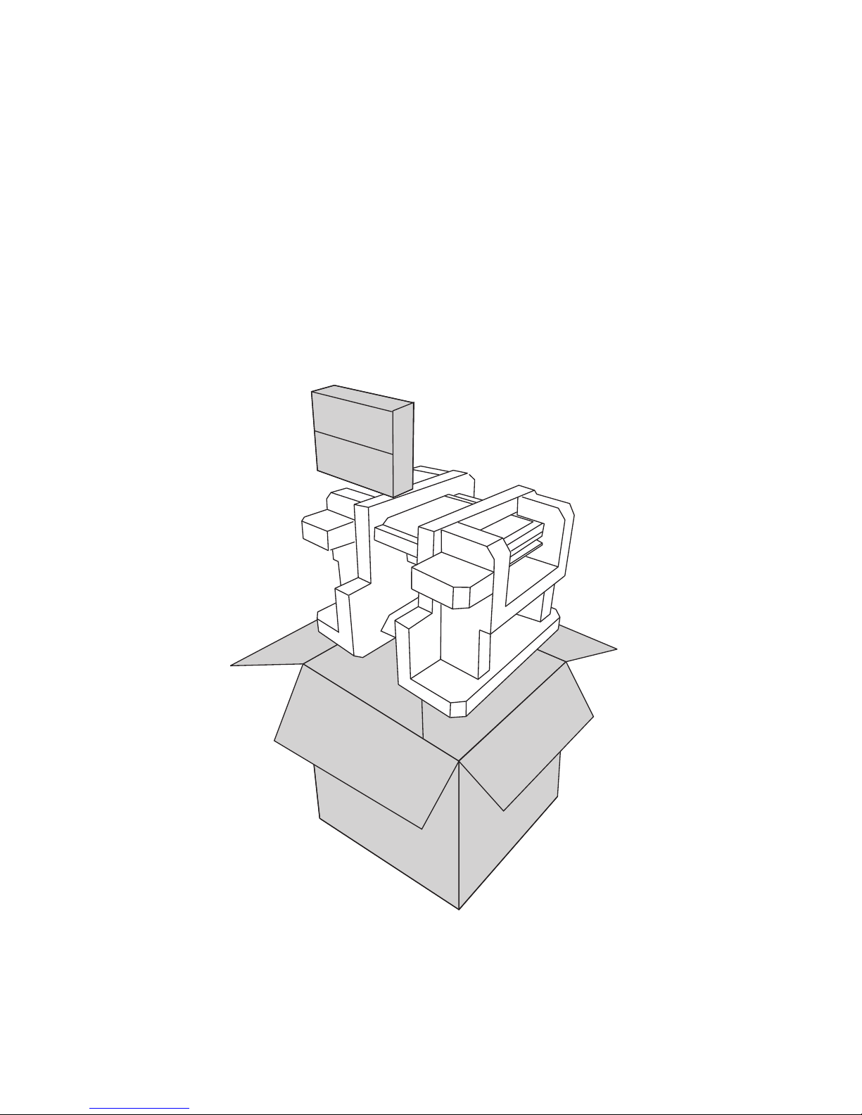
Unpacking the machine
It is a good idea to save the packaging materials and shipping box in case that machine needs to be returned
for service. Please un-pack and re-pack the machine terminal as shown in Figure 1.1.
Figure 1.1 Unpacking the
machine
Page 10
2 C H A P T E R 1 G E T T I N G S T A R T E D
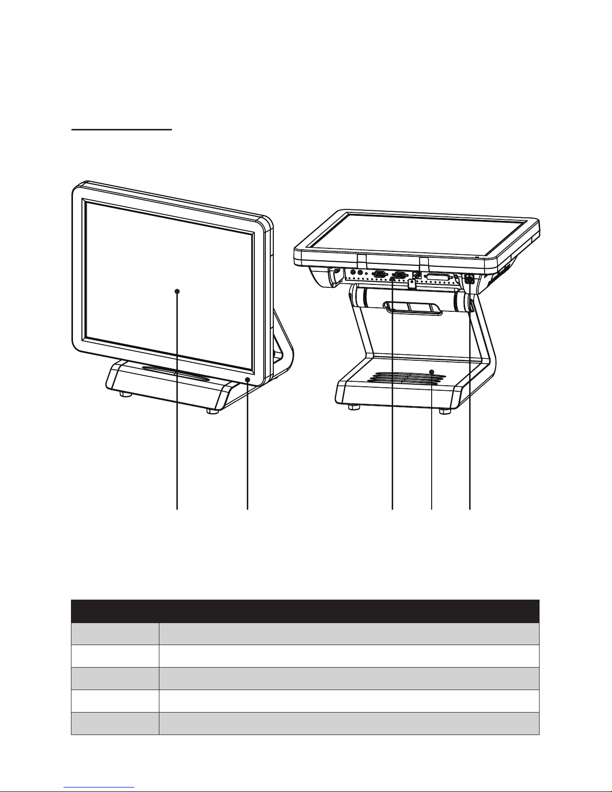
Identifying components
This section describes the parts and connectors on the machine.
1 2
Figure 1.2 Front-right view
Component Description
1 15-inch TFT LCD
2 LED Power Indicator
3 IO Panel
4 HDD Compartment
5 Power Button
3 54
Front-right view
Page 11
3
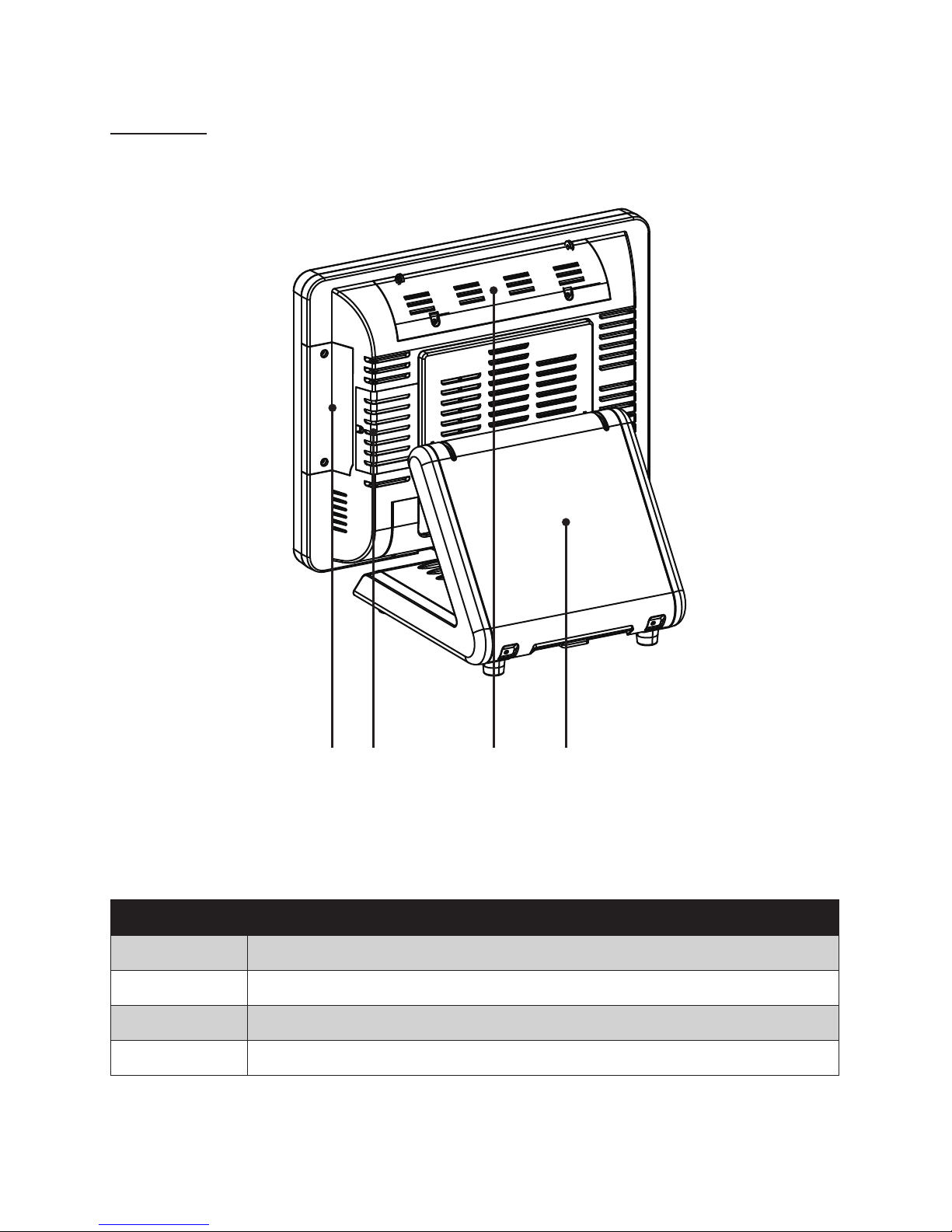
Rear view
1 2 3 4
Figure 1.3 Rear view
Component Description
1 MSR (optional) Slot
2 HDD Compartment (for wall mounting)
3 VFD Customer Display (optional) Slot
4 Cable Compartment
Page 12
4 C H A P T E R 1 G E T T I N G S T A R T E D
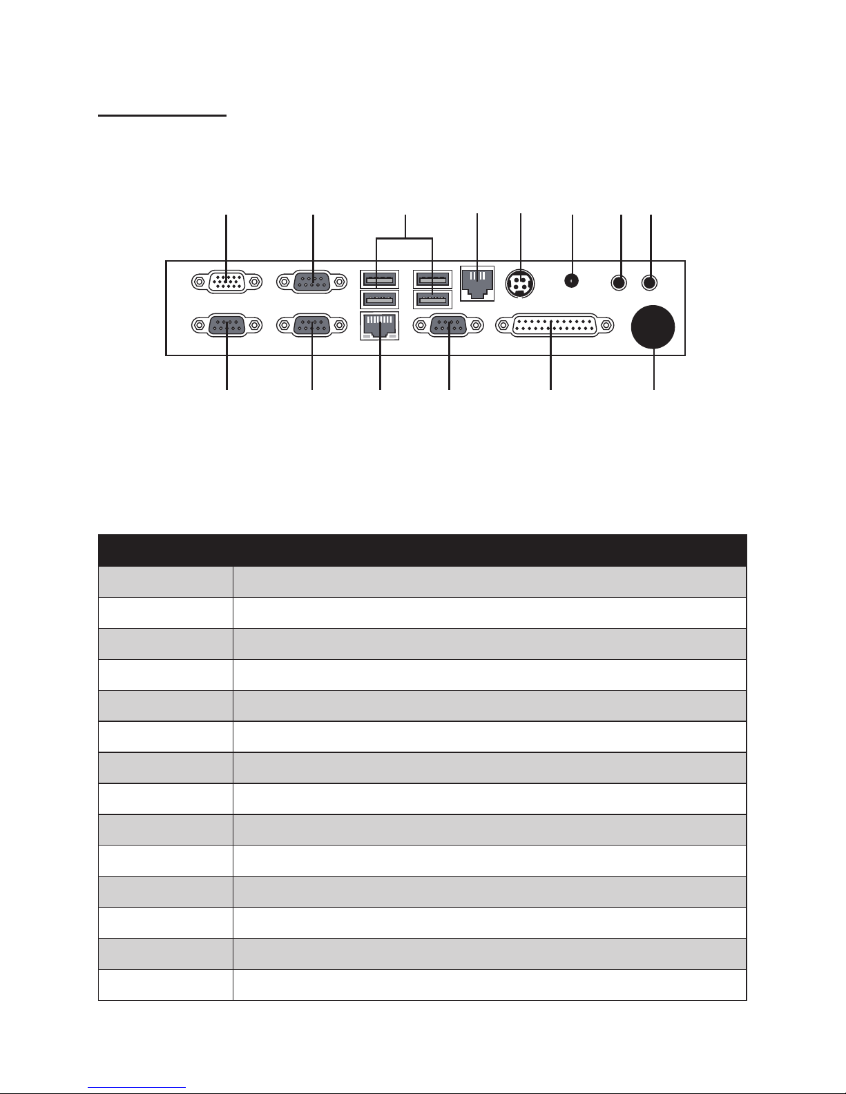
I/O connectors
Figure 1.4 SP-1000-C I/O connectors
6321 4 5 7 8
9 10 11 12 13 14
Connector Description
1 VGA port
2 COM 2 port
3 USB ports
4 RJ11 cash drawer port
5 DC 12V input connector
6 DC 12V output connector (for PM-116)
7 Microphone jack
8 Audio output jack
9 COM 3 port
10 COM 1 port
11 LAN jack
12 COM 4 port
13 LPT port
14 SATA cable hole
Page 13

5
CHAPTER 2
BIOS SETUP
The primary function of the BIOS (Basic Input and Output System) is to identify and initiate component
hardware. The BIOS parameters are stored in non-volatile BIOS memory (CMOS). CMOS contents don’t get
erased when the computer is turned off. The following topics are described in this chapter.
• About the Setup Utility on page 5
• Main Screen on page 8
• Intel Settings on page 10
• Security Settings on page 20
• Boot Settings on page 21
• Exit Menu on page 22
About the Setup Utility
The BIOS Setup Utility enables you to congure the following items:
• Hard drives, diskette drives, and peripherals
• Video display type and display options
• Password protection from unauthorized use
• Power management features
This Setup Utility should be used for the following:
• When changing the system conguration
• When a conguration error is detected and you are prompted to make changes to the Setup Utility
• When trying to resolve IRQ conicts
• When making changes to the Power Management conguration
• When changing the User or Supervisor password
Page 14
6 C H A P T E R 2 B I O S S E T U P
Entering the Setup Utility
When you power on the system, BIOS enters the Power-On Self Test (POST) routines. POST is a series of
built-in diagnostics performed by the BIOS. After the POST routines are completed, the following message
appears:
Press <F2> to enter SETUP
Press the delete key <F2> to access the BIOS Setup Utility:
BIOS navigation keys
The BIOS navigation keys are listed below.
Key Function
← → Select screens
↑ ↓ Select items
+ – Modies the selected eld’s values
Enter Go to sub screen
F1 Displays a screen that describes all key functions
F10 Saves the current conguration and exits Setup
Esc Exits the current screen
Figure 2.1 Main BIOS screen
Page 15

7
Using BIOS
When you start the Setup Utility, the main screen appears. The main screen of the Setup Utility displays a list
of the options that are available. A highlight indicates which option is currently selected. Use the cursor arrow
keys to move the highlight to other options. When an option is highlighted, execute the option by pressing
<Enter>.
Some options lead to pop-up dialog boxes that prompt you to verify that you wish to execute that option.
Other options lead to dialog boxes that prompt you for information.
Some options (marked with a triangle ►) lead to sub screens that enable you to change the values for the
option. Use the cursor arrow keys to scroll through the items in the sub screen.
Page 16

8 C H A P T E R 2 B I O S S E T U P
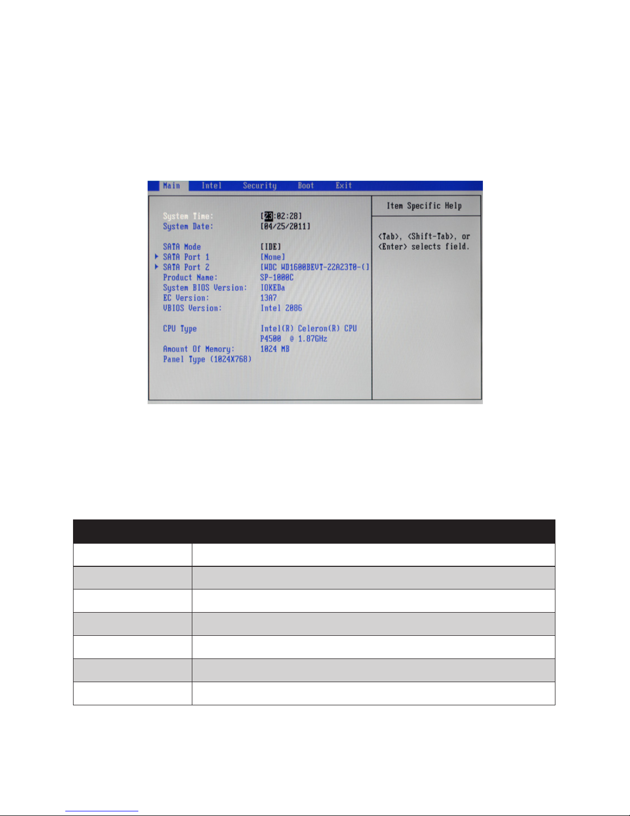
Main Screen
This screen includes System BIOS Information, Processor, System memory and displays the System Time
and System Date.
System Time/ System Date
The System Time and System Date items show the current date and time held by the machine. If you are
running a Windows OS, these items are automatically updated whenever you make changes to the Windows
Time and Date Properties utility.
SATA Mode
This feature allows users to select SATA mode.
System Overview
This screen displays Product Name, System BIOS Information, Processor Type, System memory and Panel
Type.
Figure 2.2 Main Screen
Page 17
9
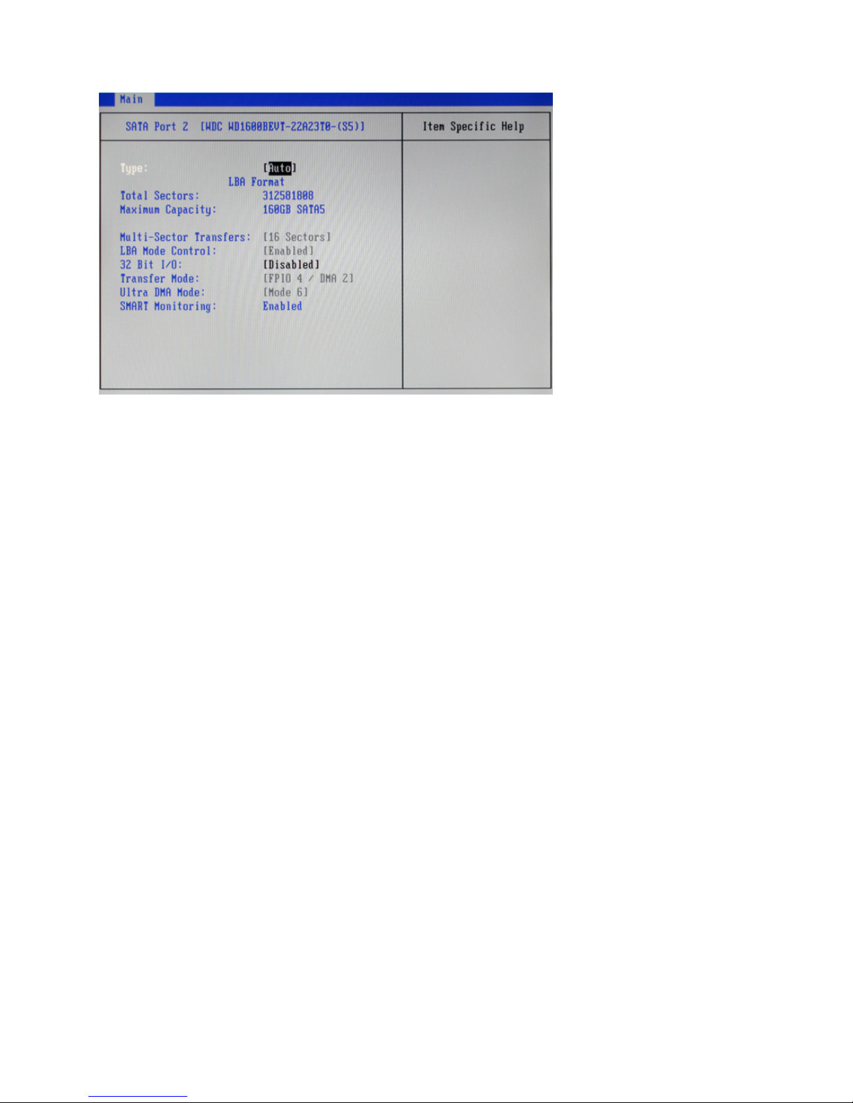
SATA Port 1/ 2
Type
This item automatically detect hard disk drive. The BIOS Setup automatically lls in the correct values for the
remaining elds on this sub-menu.
LBA Format
LBA Format for a hard disk > 512 MB under DOS and Windows.
Total Sectors
Displays the total number of sectors.
Maximum Capacity
Displays the capacity of the hard disk.
Multi-Sector Transfers
This item will enhance hard disk performance by reading or writing more data during each transfer.
LBA Mode Control
This item shows the status of LBA mode.
32 Bit I/O
It allows user to enable 32-bit access to maximize the hard disk data transfer rate.
Ultra DMA Mode
This item shows status of the Ultra Direct Memory Access (DMA) mode.
SMART Monitoring
This item is used to enable monitoring of hard disks that support the S.M.A.R.T. (Self-Monitoring And
Reporting Technology) feature, which can allow the hard disk to report, under some circumstances,
impending failures of the hard disk.
Figure 2.3 SATA Port submenu
Page 18
10 C H A P T E R 2 B I O S S E T U P
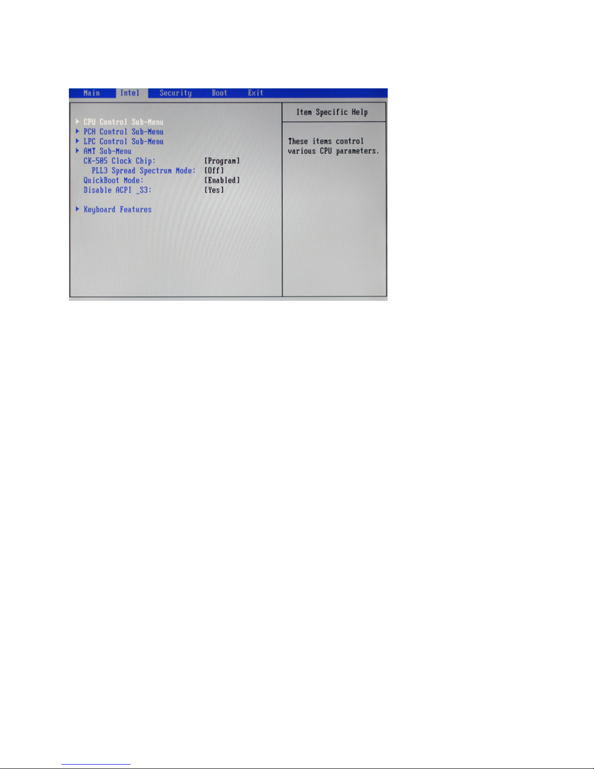
CK-505 Clock Chip:
This item allows user to select control programming of the CK-505 clock chip.
PLL3 Spread Spectrum Mode
This item is used to On/Off Spread Spectrum support for PLL3 in the CK-505 clock chip.
QuickBoot Mode
Enabling this setting will cause the BIOS power-on self test routine to skip some of its tests during booting
for faster system boot.
Disable ACPI _S3
This item allows user to select if disable the ACPI (Advanced Conguration and Power Interface) S3
function.
Intel Settings
This screen allow you to congure the Intel features.
Figure 2.4 Intel Settings
screen
Page 19
11
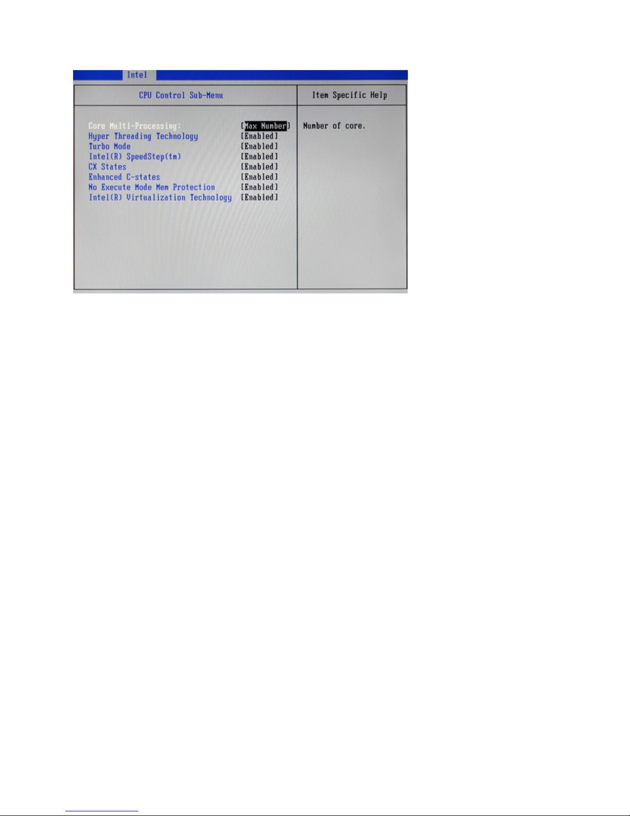
CPU Control Sub-Menu
Core Multi-Processing
This option is used to select the number of CPU core .
Hyper Threading Technology
This item is used to enable/ disable Hyper Threading Technology.
Turbo Mode
This item is used to enable/ disable Turbo Mode.
Intel(R) SpeedStep(tm)
This item is used to enable/ disable Intel SpeedStep, that allow the clock speed of the processor to be
dynamically changed by software.
CX States
This item is used to enable/ disable CX States.
Enhanced C-states
This item is used to enable/ disable Enhanced C-states.
No Execute Mode Mem Protection
This item is used to enable/ disable the function of No Execute Mode Mem Protection.
Intel(R) Virtualization Technology
This item is used to enable/ disable the function of Intel Virtualization Technology.
Figure 2.5 CPU Control
sub-menu
Page 20

12 C H A P T E R 2 B I O S S E T U P
PCH Control Sub-Menu
Figure 2.6 PCH Control
sub-menu
PXE OPROM
This item is used to enable/ disable PXE Option ROMs.
Wake-On-Lan (WOL)
This item is used to enable/ disable Wake-On-Lan, that allows the system to be woken up by a network
message.
States After G3:
This item allows user to specify what system power state to go to when power restoration.
Page 21
13
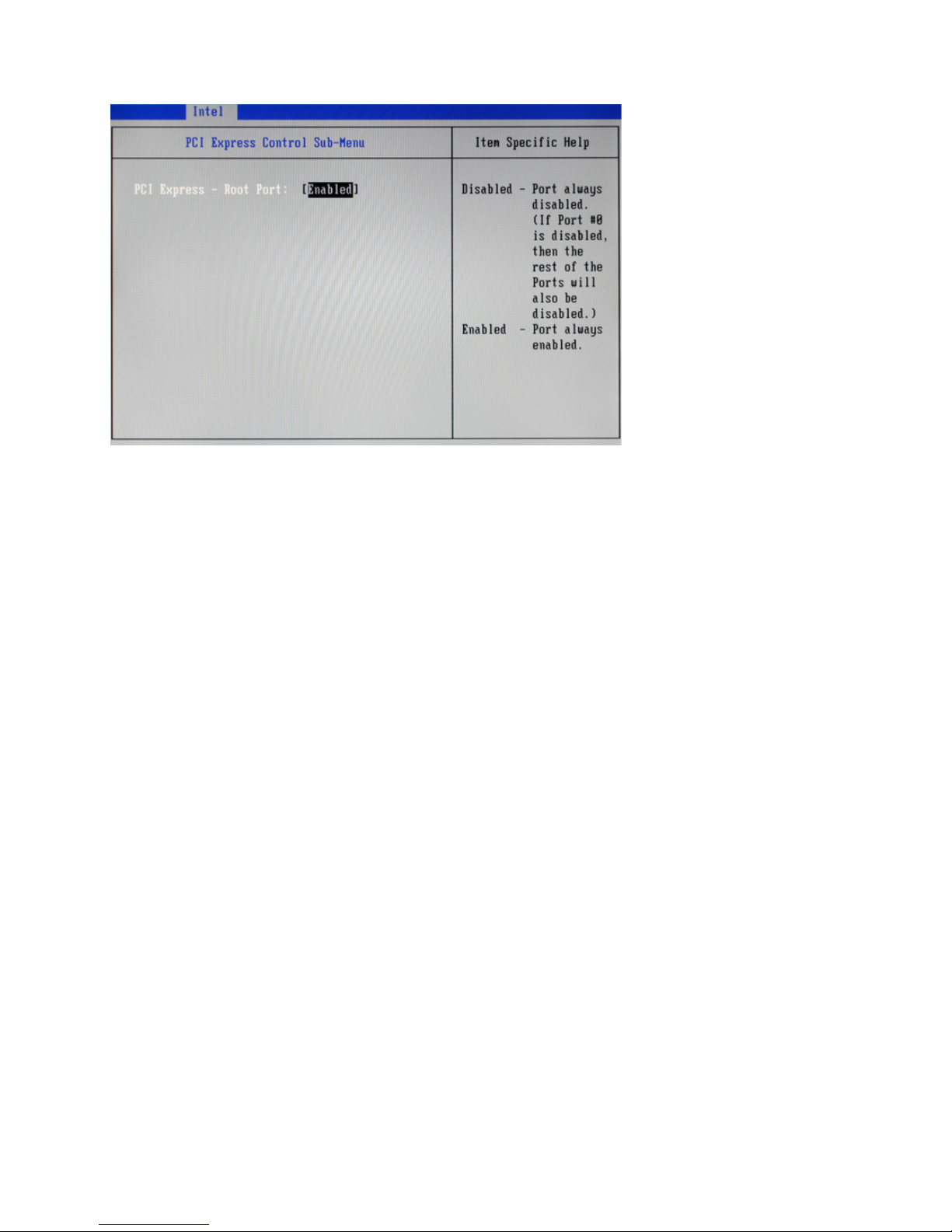
PCI Express Control Sub-Menu
Figure 2.7 PCI Express
Control sub-menu
PCI Express - Root Port
This feature is used to enable/ disable the PCI Express Root Port.
Page 22

14 C H A P T E R 2 B I O S S E T U P
LPC Control Sub-Menu
Figure 2.8 LPC Control
sub-menu
Page 23

15
SIO Control Sub-Menu
COM 1/ 2/ 3/ 4/ 5/ 6 Conguration:
COM:
These items are used to enable/ disable the COM port 1/ 2/ 3/ 4/ 5/ 6.
ADDR:
These items are used to assign the I/O address for the COM port 1/ 2/ 3/ 4/ 5/ 6.
IRQ:
These items are used to assign the IRQ for the COM port 1/ 2/ 3/ 4/ 5/ 6.
LPT Conguration:
COM:
This item is used to enable/ disable the LPT port.
ADDR:
This item is used to assign the I/O address for the LPT port.
Figure 2.9 SIO Control
sub-menu
Page 24

16 C H A P T E R 2 B I O S S E T U P
IRQ:
This item is used to assign the IRQ for the LPT port.
LPT Mode:
This item allows user to select the LPT port mode.
Page 25

17
H/W Monitor Sub-Menu
Backlight Control
This item allow user to control the backlight brightness.
Chassis Intrusion
This item is used to enable/ disable chassis intrusion, this feature can alert you when your computer chassis is
opened.
Figure 2.10 H/W Monitor
Sub-Menu
Page 26

18 C H A P T E R 2 B I O S S E T U P
AMT Sub-Menu
UnCongure ME:
This item is used to enable/ disable the function of Intel UnCongure ME.
MeFwDowngrade:
This item is used to enable/ disable the function of Intel MeFwDowngrade.
Figure 2.11 AMT sub-menu
Page 27

19
Keyboard Feature Sub-Menu
NumLock:
This function is used to set the state of the keyboard’s numlock function after POST.
Typematic Rate Setting
This feature allows you to gain manual control of the keystroke repeat feature.
Figure 2.12 Keyboard
Feature Sub-Menu
Page 28

20 C H A P T E R 2 B I O S S E T U P
Security Settings
This screen allows you to congure the system security settings.
Figure 2.13 Security
Settings screen
Supervisor/ User Password
Indicates whether a supervisor/ user password has been set. If the password has been installed, Set displays. If
not, Clear displays.
Set Supervisor/ User Password
These items can be used to install a password. A Supervisor password takes precedence over a User password,
and the Supervisor can limit the activities of a User. To install a password, follow these steps:
1. Highlight the item Set Supervisor/ User Password on the Security menu and press <Enter>.
2. The password dialog box appears.
3. If you are installing a new password, type in the password. You can type up to eight alphanumeric characters. Symbols are ignored. The Set Supervisor/ User Password item differentiates between upper and lower
case characters. Press <Enter> after you have typed in the password. To conrm the password, type the
password again and press <Enter>. To clear the password, leave the dialog box blank, press <Enter>, when
the conrm box appears, press <Enter> again.
4. Write the passwords down and keep them in a safe place.
Fixed disk boot sector:
This feature provides rudimentary anti-virus protection by write-protecting the boot sector. Set to [Write
Protect], the BIOS will block any attempt to write to the boot sector.
Password on boot
When enabled, system will ask input password on post time. When disabled, system will ask input password
when go to Setup Utility.
Page 29

21
Boot Settings
This screen allow you to congure the boot options.
Figure 2.14 Boot Settings
screen
Boot priority order:
Set the boot device options to determine the sequence in which the computer checks which device to boot
from.
Page 30

22 C H A P T E R 2 B I O S S E T U P
Exit Saving Changes
Highlight this item and press <Enter> to save the changes that you have made in the Setup Utility and exit
the Setup Utility. When the dialog box appears, select <Yes> to save and exit, or select <No> to return to the
menu.
Exit Discarding Changes
Highlight this item and press <Enter> to discard any changes and exit.
NOTE
If you have made settings that you do not want to save, use the “Exit
Discarding Charges” item to discard any changes you have made.
Load Setup Defaults
This option opens a dialog box that lets you load setup defaults for all appropriate items in the Setup Utility.
The setup defaults place no great demands on the system and are generally stable. If the system is not
functioning correctly, try loading the setup defaults as a rst step in getting the system working properly
again. If you only want to load setup defaults for a specic option, select and display that option, and then
press <F9>.
Follow these instructions: to load the setup defaults:
1. From the Exit screen, scroll to Load Setup Defaults.
2. Press <Enter> to open the Load Setup Defaults screen.
3. Select <Yes>.
4. Press <Enter> to load the defaults.
Discard Changes
Highlight this item and press <Enter> to discard any changes that you have made in the Setup Utility. When
the dialog box appears, select <Yes> to discard changes, or select <No> to return to the menu.
Exit Menu
This screen allows you to load the default values, and save or discard changes.
Figure 2.15 Exit Menu
screen
Page 31

23
Save Changes
Highlight this item and press <Enter> to save the changes that you have made in the Setup Utility. When the
dialog box appears, select <Yes> to save changes, or select <No> to return to the menu.
Page 32

24 C H A P T E R 2 B I O S S E T U P
Page 33

25
CHAPTER 3
INSTALLING DRIVERS AND SOFTWARE
This section explains how to install the drivers for the SP-1000-C.
The following topics are described.
• Driver auto installation on the page 31
• Intel Chipset Driver on the page 32
• Intel Management Engine Driver on the page 34
• Intel Chipset Graphics Driver on the page 36
• HD Audio driver on the page 38
• LAN Driver on the page 39
• Touch Screen Driver on the page 42
Driver auto installation
Use an external CD-ROM drive to install the drivers or copy the drivers to a USB ash drive and then plug to
the machine. When you insert the CD ROM the following screen appears.
Check SP-1000-C that is listed under the “Install Terminal Drivers” and “Install Device Drivers” menus.
Page 34

26 C H A P T E R 3 I N S T A L L I N G D R I V E R S A N D S O F T WA R E
Intel Chipset Driver
The Intel Chipset Device Software updates the Windows XP/7 INF les so that the Intel chipset is correctly
congured. Follow these instructions to install the chipset software :
1. Browse to the \DRIVER\chipset\Intel\Inf folder.
2. Double-click setup.exe. The following screen appears. Click Next to continue.
3. Read the license agreement, then click Yes.
Page 35

27
4. Browse the ReadMe Information, then click Next.
5. The Intel Chipset Software Utility les are installed to the system. When prompted to restart, select
Yes, I want to restart my computer now. Then click Finish to restart the system.
Page 36

28 C H A P T E R 3 I N S T A L L I N G D R I V E R S A N D S O F T WA R E
Intel Management Engine Driver
If the Intel Management Engine driver has not been successfully installed, you may see an error on a “PCI
Simple Communications Controller” in Device Manager.
To install the drivers.
1. Browse to the \DRIVER\chipset\Intel\MEI folder.
2. Double-click setup.exe. The following screen appears. Click Next to continue.
3. Read the license agreement, then click Yes.
Page 37

29
4. Browse the ReadMe Information, then click Next.
5. The Intel Management Engine Driver is installed to the system. Click Finish to complete the
process.
Page 38

30 C H A P T E R 3 I N S T A L L I N G D R I V E R S A N D S O F T WA R E
Intel Chipset Graphics Driver
This utility installs the Intel Extreme Graphics 2 drivers for Windows XP/2000. To install the drivers.
1. Browse to the \DRIVER\VGA\intel\ folder.
2. Double-click the executable le. The following screen appears. Read the release version, and then
click Next.
3. Read the license agreement, then click Yes.
Page 39

31
4. Browse the ReadMe Information, then click Next.
5. When installation is completed, select Yes, I want to restart my computer now. Then click Finish
to restart the system.
Page 40

32 C H A P T E R 3 I N S T A L L I N G D R I V E R S A N D S O F T WA R E
HD Audio driver
Refer to the following to install the Realtek drivers.
1. Browse to the \DRIVER\SOUND\RealTek folder.
2. Click Yes, I want to restart my computer now and then click Finish.
Page 41

33
LAN Driver
The network driver support Windows XP/2000. Refer to the following to install the drivers.
1. Browse to the \DRIVER\LAN\intel folder.
2. Double-click the executable le. The following screen appears. Click Install Drivers and
Software.
3. Read the license agreement and select I accept the terms in the license agreement, then click
Next.
Page 42

34 C H A P T E R 3 I N S T A L L I N G D R I V E R S A N D S O F T WA R E
4. Click Next.
5. Click Install.
Page 43

35
6. Click Finish to complete the process.
Page 44

36 C H A P T E R 3 I N S T A L L I N G D R I V E R S A N D S O F T WA R E
Touch Screen Driver
Refer to the following to install the touch screen driver.
1. Browse to the \DRIVER\Touch\eGalax folder.
2. Double-click setup.exe. The following screen appears. Click Next to continue.
3. Check the box for Install PS/2 interface drive and then click Next to continue.
Page 45

37
4. System will give you a warning, click Ok to continue.
5. Check the box for None and then click Next to continue.
6. Uncheck the box for Support Mulit-Monitor System and then click Next to continue.
Page 46

38 C H A P T E R 3 I N S T A L L I N G D R I V E R S A N D S O F T WA R E
7. Click Next to continue.
8. Click Next to continue.
Page 47

39
9. Click Yes, I want to restart my computer now and then click Finish.
Calibrating the touchscreen
Follow these instructions to calibrate the touchscreen using the TouchKit application:
1. Launch the TouchKit application from the Windows desktop by clicking on Start > Programs > TouchKit
> Congure Utility. The TouckKit window appears.
2. Select the Tools page.
Page 48

40 C H A P T E R 3 I N S T A L L I N G D R I V E R S A N D S O F T WA R E
3. Click the 4 Points Calibrattion button.
4. Use your nger to touch the blinking X Symbol on the screen until stop blinking.
5. Click OK to complate the 4 points calibration.
You may also use this application to adjust the touch settings.
NOTE
Page 49

41
CHAPTER 4
LOCATING THE PROBLEM
Refer to this section to locate the problem with the machine. The following topics are described.
• General checkout guidelines on the page 45
• Cash drawer checkout on the page 45
• LCD symptoms on the page 46
• Touch screen symptoms on the page 47
• Power symptoms on the page 47
• Network symptoms on the page 47
• USB symptoms on the page 48
• Peripheral-device symptoms on the page 48
• Boot symptoms on the page 48
• Mainboard jumper on the page 49
• Mainboard connectors on the page 50
• Inverter connectors on the page 50
General checkout guidelines
Use the following procedure to troubleshoot problems:
• Identify as many symptoms as possible in detail.
• Verify symptoms by recreating them.
• Follow the corrective procedures in order.
• If you replace an FRU and the symptom remains, reinstall the original FRU before going to the next step.
Do not replace non-defective FRUs.
Cash drawer checkout
Refer to the following to check for a cash drawer problem.
1. Connect the RJ-11 cable from the cash drawer to the RJ-11 connector on the machine as shown in Figure
4.1.
The cash drawer RJ-11 connector is DC+24V. Ensure the cash drawer
to be connected matches this power specication.
IMPORTANT
Page 50

42 C H A P T E R 4 L O C A T I N G T H E P R O B L E M
Refer to the following to prevent incorrect cash drawer status detection by the system:
Port I/O Port Address Bit Condition Note
Cashdrawer A
Control port
F1 0
High(1) → Close
Low(0) → Open
If Bit is set to Low to open the
cash drawer, after it must be set
back to High to prevent the system
as always detecting the drawer as
open.
Cashdrawer B
Control port
F1 1
High(1) → Close
Low(0) → Open
Cashdrawer A
Status port
F1 2
High(1) → Close
Low(0) → Open
Cashdrawer A
Status port
F1 3
High(1) → Close
Low(0) → Open
LCD symptoms
Symptom Corrective Procedure
• LCD backlight is not working but text is still visible on
screen
1. Reseat the LCD cable.
2. Reseat the inverter cables.
3. Replace the inverter cables.
4. Replace the inverter.
• LCD backlight is working but text is not visible on screen 1. Reseat the LCD cable.
2. Reseat the inverter cables.
3. Replace the LCD.
• LCD screen is garbled
• Characters are missing pixels
• Screen is distorted
• Screen displays wrong color
• Screen displays extra vertical/horizontal lines
1. Reseat the LCD cable.
2. Replace the inverter cables.
3. Replace the LCD panel.
4. Replace the mainboard.
Cashdrawer
Figure 4.1 Connecting a
cash drawer
2. Turn on the machine .
Page 51

43
Touch screen symptoms
Symptom Corrective Procedure
• Touchscreen does not
function
• No virtual mouse
• Cursor doesn’t follow when
touching the screen
1. Install and run the touchscreen calibration program from the driver
CD.
2. Reseat the panel cable.
3. Reseat the touchscreen board-to-touch panel cable.
4. Replace the touch control board.
5. Replace the touch panel.
Power symptoms
Symptom Corrective Procedure
• Power shuts down unexpectedly
• Cannot turn the system on
1. Reseat the power AC adapter cable.
2. Reseat the power AC adapter.
3. Replace the mainboard.
• Cannot turn the system off 1. Hold down the power button for four seconds.
2. Replace the mainboard.
Network symptoms
Symptom Corrective Procedure
• Cannot access LAN 1. Conrm that network hub/switch (if present) is functioning
correctly.
2. Reseat the RJ-45 cable.
3. Conrm green and orange LED activity of the RJ-45 jack.
4. Check the network TCP/IP settings.
5. Remove and reinstall the driver.
6. Replace the network cable.
7. Replace the mainboard.
Page 52

44 C H A P T E R 4 L O C A T I N G T H E P R O B L E M
USB symptoms
Symptom Corrective Procedure
• USB device does not function 1. Check that the USB device is detected in Windows Device
Manager.
2. Reinstall the USB device driver.
3. Replace the mainboard.
Peripheral-device symptoms
Symptom Corrective Procedure
• USB ports do not work
• COM ports do not work
1. Reseat the I/O cable.
2. Reinstall the drivers.
3. Replace the mainboard.
Boot symptoms
Symptom Corrective Procedure
• System continually reboots on
power up
1. Restore the BIOS defaults.
2. Remove all I/O device drivers, then reinstall the drivers one
by one.
3. Reseat the SATA cable.
4. Reseat the memory card.
5. Reseat the power adapter.
6. Replace the mainboard.
Page 53

45
Mainboard jumper
JCMOS
Figure 4.2 SP-1000-C mainboard jumper
Jumper Setting Description
JCMOS
1-2 closed (default) Normal
2-3 closed Clear CMOS
Page 54

46 C H A P T E R 4 L O C A T I N G T H E P R O B L E M
Figure 4.4 Inverter connectors
Inverter connectors
connector to
mainboard
connector to
LCD
connector to
LCD
Figure 4.3 SP-1000-C mainboard connectors
Mainboard connectors
connector to
inverter
connector to
LCD panel
connector to
MSR
connector to
SATA HDD
connector to
HDD power
connector to
audio jacks
connector to
speaker
connector to
touch panel
connector to
COM4 port
connector to
parallel port
connector to
CPU fan
connector to
power LED
connector to
power button
connector to
power jack
Page 55

47
CHAPTER 5
REPLACING FIELD REPLACEABLE UNITS (FRUs)
This chapter provides instructions for replacing FRUs. The following topics are described.
• Safety and precautions on the page 51
• Before you begin on the page 52
• Replacing parts on the page 52
• MSR on the page 53
• Customer Display on the page 53
• HDD on the page 54
• SP-1000-C Panel on the page 55
• Panel Back Cover on the page 56
• Speaker on the page 57
• Power Button on the page 58
• CPU Cooling Fan on the page 59
• Memory on the page 60
• Battery on the page 60
• I/O Shield on the page 61
• Mainboard Board on the page 62
• Inverter on the page 63
• Panel Bracket on the page 64
• Waterproof Seal, Touch Panel, Touch Cover, LCD Panel on the page 64
Only qualied personnel should perform repairs on the SP-1000-C.
Damage due to unauthorized servicing is not covered by the warranty.
Safety and precautions
Computer components and electronic circuit boards can be damaged by discharges of static electricity.
Working on computers that are still connected to a power supply can be extremely dangerous. Follow these
guidelines to avoid damage to the computer or injury to yourself.
• Always disconnect the unit from the power outlet.
• Leave all components inside the static-proof packaging that they ship with until they are ready for
installation.
• After replacing optional devices, make sure all screws, springs, or other small parts are in place and
are not left loose inside the case. Metallic parts or metal akes can cause electrical shorts.
If the LCD breaks and uid gets onto your hands or into your eyes,
immediately wash with water and seek medical attention.
CAUTION
CAUTION
Page 56

48 C H A P T E R 5 R E P L A C I N G F I E L D R E P L A C E A B L E U N I T S ( F R U s )
To prevent static damage to components, wear a grounded wrist strap.
Alternatively, discharge any static electricity by touching the bare metal
chassis of the unit case, or the bare metal body of any other grounded
appliance.
Hold electronic circuit boards by the edges only. Do not touch the
components on the board unless it is necessary to do so. Do not ex or
stress the circuit board. Do not hold components such as a processor
by its pins; hold it by the edges.
To prevent scratching the case of the SP-1000-C, make sure the worktop
surface is clean and at. If you need to put the display facing down, be
sure to use a foam mat.
Before you begin
Make sure you have a stable, clean working environment. Dust and dirt can get into the SP-1000-C components and may cause malfunction. Adequate lighting and proper tools can prevent you from accidentally
damaging the internal components. Most of the electrical and mechanical connections can be disconnected
by using your ngers. It is recommended that you do not use needle-nosed pliers to disconnect connectors as
these can damage the soft metal or plastic parts of the connectors.
Replacing parts
Take note of the following when replacing parts:
• If you replace an FRU and the symptom remains, reinstall the original FRU before going to the next
step. Do not replace non-defective FRUs.
• When replacing a malfunctioning component, other parts that have to be removed before the failing
part are listed at the top of the page.
• The arrows in the following procedures show the direction of movement to remove/replace a part, or
to turn a screw or key to release a device.
• Always use the correct screw size as indicated in the procedures.
• Always use new screws.
• To replace a part, reverse the removal procedure.
CAUTION
CAUTION
CAUTION
Under no circumstances touch the inverter while power is connected to
the machine. Unplug the power cord before attempting to replace any
FRU.
CAUTION
Page 57

49
MSR
1. Remove two screws.
2. Disconnect the cable.
3. Remove the MSR.
Customer Display
1. Remove two screws.
2. Disconnect the cable.
3. Remove the customer display.
Page 58

50 C H A P T E R 5 R E P L A C I N G F I E L D R E P L A C E A B L E U N I T S ( F R U s )
HDD
1. Rotate the LCD screen forward .
2. Press and the hard drive compartment cover as it shown on
the picture.
3. Turn the screw counterclockwise
to loosen the hard drive tray.
HDD
4. Slide the hard drive tray.
5. Disconnect the power cable and
SATA cable from the hard drive.
HDD
6. Remove the four screws, then
remove the hard drive out from
the tray.
HDD
Page 59

51
SP-1000-C Panel
1. Rotate the LCD screen forward .
2. Remove the screw that secure the
base to the SP-1000-C.
The screen is
fragile. Placing
the monitor
face-down
on a at, soft
area prevents
scratches,
defacing, or
breakage.
CAUTION
3. Disconnect cables from HDD.
4. Lift the panel and remove it from
the base.
Page 60

52 C H A P T E R 5 R E P L A C I N G F I E L D R E P L A C E A B L E U N I T S ( F R U s )
Panel Back Cover
Before proceeding, remove
the following FRUs.
• “SP-1000-C Panel” on
page 51.
1. Remove two screws.
2. Gently pull away the top
of back cover, then open
the back cover.
Page 61

53
Speaker
Before proceeding, remove the
following FRUs.
• “SP-1000-C Panel” on page
51.
• “Panel Back Cover” on page
52.
1. Remove two screws from the
speaker bracket.
2. Remove two screws.
3. Disconnect the cable from
the mainboard.
4. Remove the speaker.
Page 62

54 C H A P T E R 5 R E P L A C I N G F I E L D R E P L A C E A B L E U N I T S ( F R U s )
Power Button
Before proceeding, remove the
following FRUs.
• “SP-1000-C Panel” on page
51.
• “Panel Back Cover” on page
52.
1. Remove two screws from the
power button bracket.
2. Remove two screws.
3. Disconnect the cable from
the mainboard.
4. Remove the power button.
Page 63

55
CPU Cooling Fan
Before proceeding, remove
the following FRUs.
• “SP-1000-C Panel” on
page 51.
• “Panel Back Cover” on
page 52.
1. Remove six screws from
the mainboard cover.
2. Remove the mainboard
cover.
3. Remove four screws from
the CPU cooling fan.
4. Remove the CPU cooling
fan.
Page 64

56 C H A P T E R 5 R E P L A C I N G F I E L D R E P L A C E A B L E U N I T S ( F R U s )
Memory
Before proceeding, remove the following
FRUs.
• “SP-1000-C Panel” on page 51.
• “Panel Back Cover” on page 52.
1. Pop out the two silver latches holding the
memory module into place. The module
pops up.
2. Grasp the outer edges of the memory
module with thumb and forenger, and
then gently remove it.
Battery
Before proceeding, remove the following FRUs.
• “SP-1000-C Panel” on page 51.
• “Panel Back Cover” on page 52.
1. Use ngers to pull out the battery.
Page 65

57
I/O Shield
Before proceeding, remove the
following FRUs.
• “SP-1000-C Panel” on page
51.
• “Panel Back Cover” on page
52.
1. Remove all screws from the
I/O ports.
2. Remove two screws from the
I/O shield.
3. Remove the I/O shield.
Page 66

58 C H A P T E R 5 R E P L A C I N G F I E L D R E P L A C E A B L E U N I T S ( F R U s )
Mainboard Board
Before proceeding, remove the
following FRUs.
• “SP-1000-C Panel” on page
51.
• “Panel Back Cover” on page
52.
• “CPU Cooling Fan” on page
55.
• “I/O Shield” on page 57.
1. Disconnect all cables from
the mainboard.
2. Remove four screws.
3. Remove the mainboard.
Page 67

59
Inverter
Before proceeding, remove the
following FRUs.
• “SP-1000-C Panel” on
page 51.
• “Panel Back Cover” on
page 52.
1. Remove ve screws.
2. Remove the inverter cover.
3. Remove the three screws.
4. Remove all cables from the
inverter.
5. Remove the inverter.
When replacing:
Put the inverter in the plastic
cover before replacing it.
Page 68

60 C H A P T E R 5 R E P L A C I N G F I E L D R E P L A C E A B L E U N I T S ( F R U s )
Panel Bracket
Before proceeding, remove the
following FRUs.
• “SP-1000-C Panel” on page
51.
• “Panel Back Cover” on page
52.
• “Speaker” on page 53.
• “Power Button” on page 54.
• “CPU Cooling Fan” on page
55.
• “I/O Shield” on page 57.
• “Mainboard” on page 58.
• “Inverter” on page 59.
1. Disconnect all cables.
2. Remove two screws.
3. Remove the panel bracket.
Waterproof Seal, Touch Panel, Touch Cover, LCD Panel
Before proceeding, remove
the following FRUs.
• “SP-1000-C Panel” on
page 51.
• “Panel Back Cover” on
page 52.
• “Speaker” on page 53.
• “Power Button” on page
54.
• “CPU Cooling Fan” on
page 55.
• “I/O Shield” on page 57.
• “Mainboard” on page 58.
• “Inverter” on page 59.
• “Panel Bracket” on page
60.
1. Remove four screws from
the panel bracket.
2. Remove the LCD panel.
3. Remove the touch cover
panel.
4. Remove the touch panel.
5. Remove the waterproof
seal.
Panel Bracket
LCD Panel
Touch Cover
Touch Panel
Waterproof Seal
Page 69

61
APPENDIX
PART LIST AND SPECIFICATION
Figure 6.1 Exploded diagram main parts
Page 70

62 A P P E N D I X
Figure 6.2 Exploded peripheral parts
Page 71

63
NO. DESCRIPTION ITEM NO
1 Front Cover 25000500S0101
2 Waterproof seal 25005500B0003
3 ELO Tocuh/15” 2619040000016
4 Touch Cover 25003500B0001
5 TFT LCD/15” 2614550150104
6 Panel Bracket 21004500S0001
7 MB PCB 26105500S0005
8 Heat-sink 2103200000003
9 Inverter 2614571150108
10 Inverter Cover 21004500B0045
11 W/O MSR Cover (*) 6605500M34000
12 IO Bracket 21004500S0002
13 Switch Bracket 21004500S0003
14 Power Switch 2500305013004
15 Power Button 25003500S0104
16 Panel Back Cover 25002500S0101
17 W/O VFD Cover (*) 25003500S0105
18 Speak Holder 1379999000019
19 Top Bace Cover 25003500S0100
20 HDD 160G 2.5” 2611571101600
21 2.5”HDD Bracket 21004500S0000
22 Stand Bracket 21002500S0000
23 Foot 2509030500L01
24 Panel HDD Cover 25003500S0103
25 Hinge Mount
Bracket
21004500S0004
26 Hinge Mount Cover 25003500S0107
27 Stand Front Cover 25000500S0100
28 Hinge Right 2108100000013
29 Hinge Left 2108100000014
30 Stand Right Cover 25003500S0102
31 Stand Left Cover 25003500S0101
32 Stand Back Cover
(*)
25002500S0300
33 Cable 1721209110009
34 Cable 1721211090009
35 DC Jack Cable 1721212000006
NO. DESCRIPTION ITEM NO
36 Audio Jack Cable 1721212170027
37 Inverter Cable 1721217000014
38 LCD Cable 1721217230005
39 Power Switch Cable 1721217240002
40 MSR Cable 1721317171714
41 SATA Cable 1721300282806
11-* MSR Module 770500M009205
11-1 MSR Front Cover 25000500M2002
11-2 MSR 2690605100011
11-3 MSR Bracket 25003500M2102
11-4 MSR PCB 7005000001010
11-5 MSR Back Cover 25002500M2001
17-* VFD Module 770500S090000
17-1 VFD TOP Cover 2500050410008
17-2 VFD LCD 25070500B0001
17-3 VFD PCB 7005501300030
17-4 VFD Hinge 2108100000021
17-5 VFD Hinge Bracket 21004500B0050
17-6 Mylar 2509075500M21
17-7 VFD Base Cover 2500250410007
17-8 VFD Foot 2509030500B00
17-9 VFD Connect 25003500S0106
17-10 VFD Cable 1721200170011
32-* Dual Module (PM-
116)
7705920100000
32-1 Front Cover 2500059200100
32-2 CR Mylar 2508055920000
32-3 CR Mylar 2508055920001
32-4 TFT LCD 2614551116001
32-5 LCD IO Bracket 2100459200000
32-6 WO LCD Bracket 2100459200002
32-7 Cable 1721200170025
32-8 Cable PCB 1725200000000
32-9 PCB AD Board 7005920001000
32-10 AD Board 2614590150005
32-11 Dual Connect 6605592010000
Part list for SP-1000-C
(*) is option
Page 72

64 A P P E N D I X
Specications
Item SP-1000-C D425 SP-1000-C D525
CPU Type
Intel® Atom™ processor D425 (512K
L2 Cache, 1.80 GHz, single core )
Intel® Atom™ processor D525 (1M
L2 Cache, 1.80 GHz, dual core )
LCD 15” Active TFT color LCD, resolution 1024 x 768
Touch 5-wire Resistive touch (PS2 interface)
Memory 204pin DDR3 SO-DIMM 1GB (up to 4 GB)
Ethernet 10/100M/1G
Storage Internal 2.5” type SATA HDD 160GB x 1
I/O Interface
6 * COM ports (COM1~4 at back I/O, COM5~6 on M/B)
1 * DB-15 VGA port
1 * DB-25 for LPT port
1 * RJ11 port for 2 cash drawer(+24V)
1 * PS2 Mouse port
1 * RJ-45 LAN port with activity and link LEDs
2 * Audio ports (1 * Line-out , 1 * MIC-in)
8 * USB 2.0 (4 in the back;4 on the M/B)
1 * DC +12V power adaptor connector
Expansion Options 1 * Mini PCI-e
Optional Peripherals
3 tracks magnetic reader
Customer display module (2 x 20 VFD)
1 * Mini PCI-e support WiFi function
Biometric Reader, Smart Card Reader, I-Button, RFID reader
2nd monitor(Dual screen)
Operation System Windows 7, Windows XP, XPe, Linux (ubuntu, Fedora) , WEPOS, POSReady,
Power Supply AC100~240V/DC12V
Dimensions Physical:360mm (W) x250mm (D) x 360mm (H)
Operating Temp 0~+40˚C
Storage Temperature -20˚C~+60˚C
Humidity 15%~80%
* specication subject to change without prior notice
 Loading...