

Page 1
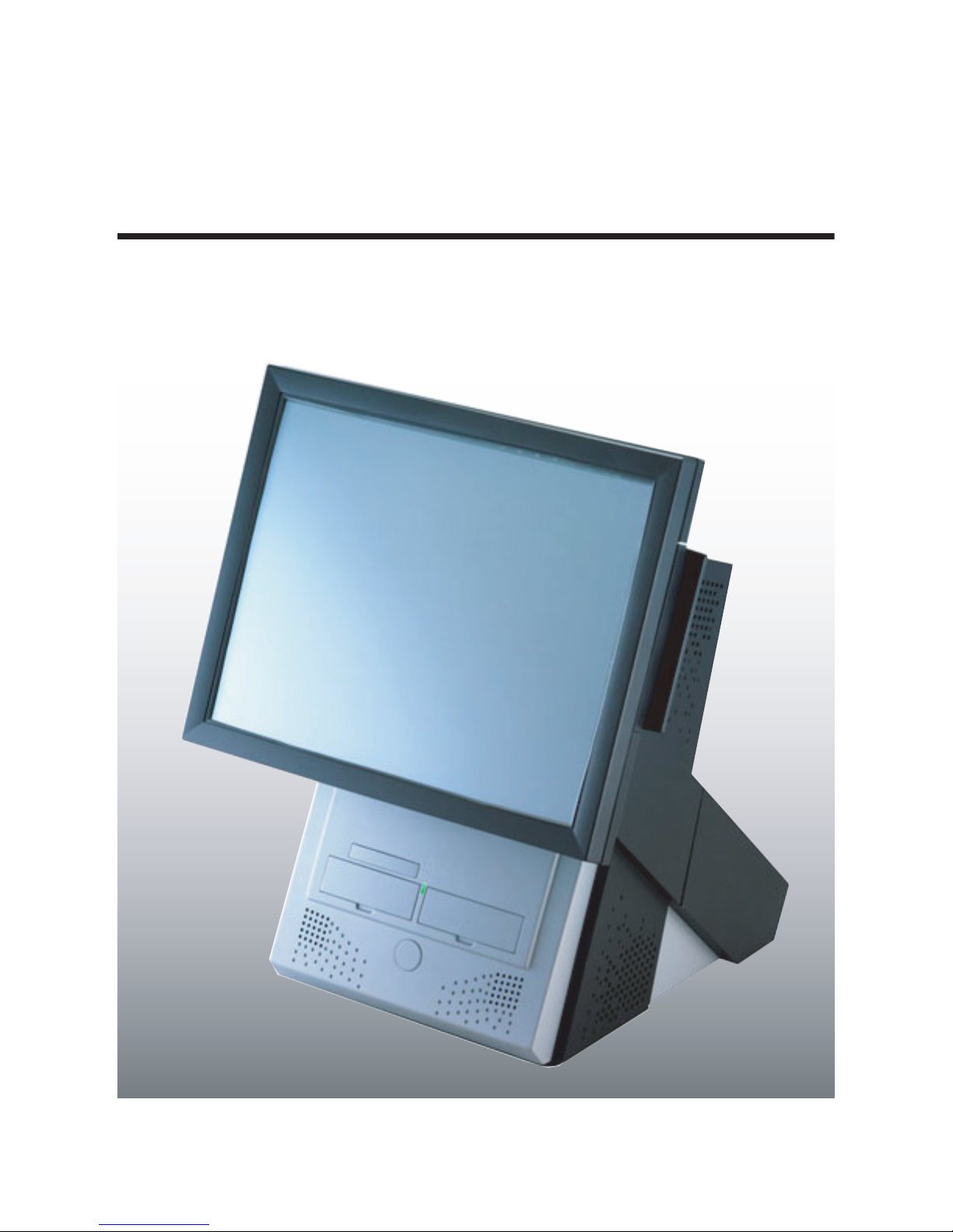
PT-8800
User manual
Page 2

Page 3

Copyright
This publication, including all photographs, illustrations and software, is protected under international copyright laws,
with all rights reserved. Neither this manual, nor any of the material contained herein, may be reproduced without written consent of the author.
Disclaimer
The information in this document is subject to change without notice. The manufacturer makes no representations or
warranties with respect to the contents hereof and specifically disclaims any implied warranties of merchantability or
fitness for any particular purpose. The manufacturer reserves the right to revise this publication and to make changes
from time to time in the content hereof without obligation of the manufacturer to notify any person of such revision or
changes.
Trademark recognition
All product names used in this manual are the properties of their respective owners and are acknowledged.
Federal Communications Commission (FCC)
This equipment has been tested and found to comply with the limits for a Class A digital device, pursuant to Part 15 of
the FCC Rules. These limits are designed to provide reasonable protection against harmful interference in a residential
installation. This equipment generates, uses, and can radiate radio frequency energy and, if not installed and used in
accordance with the instructions, may cause harmful interference to radio communications. However, there is no guarantee that interference will not occur in a particular installation. If this equipment does cause harmful interference to
radio or television reception, which can be determined by turning the equipment off and on, the user is encouraged to
try to correct the interference by one or more of the following measures:
• Reorient or relocate the receiving antenna.
• Increase the separation between the equipment and the receiver.
• Connect the equipment onto an outlet on a circuit different from that to which the receiver is connected.
• Consult the dealer or an experienced radio/TV technician for help.
Shielded interconnect cables and a shielded AC power cable must be employed with this equipment to ensure compliance with the pertinent RF emission limits governing this device. Changes or modifications not expressly approved by
the system's manufacturer could void the user's authority to operate the equipment.
Declaration of conformity
This device complies with part 15 of the FCC rules. Operation is subject to the following conditions:
• This device may not cause harmful interference, and
• This device must accept any interference received, including interference that may cause undesired operation.
About this manual
This manual is intended for system administrators who are familiar with setting up a new system and installing an
operating system.
i
Page 4
The manual consists of the following sections:
Chapter 1 Getting Started: This section covers unpacking and checking the package con-
tents, and identifying components. Information on connecting
peripheral devices, and powering on is also provided.
Chapter 2 Upgrading Components: This section provides information on upgrading components
such as a hard disk drive or CompactFlash card reader.
Chapter 3 BIOS Setup Utility: The BIOS chapter provides information on navigating and chang-
ing settings in the BIOS Setup Utility.
Appendix: The appendix covers troubleshooting, information on having the
PT-8800 serviced, and technical specifications.
Safety information
Before installing and using the PT-8800 POS, take note of the following precautions:
• Read all instructions carefully.
• Do not place the unit on an unstable surface, cart, or stand.
• Do not block the slots and opening on the unit, which are provided for ventilation.
• Do not push objects in the ventilation slots as they may touch high voltage components and result in shock and
damage to the components.
• Only use the power source indicated on the marking label. If you are not sure, contact your dealer or the Power
Company.
• The unit uses a three-wire ground cable, which is equipped with a third pin to ground the unit and prevent electric shock. Do not defeat the purpose of this pin. If your outlet does not support this kind of plug, contact your
electrician to replace your obsolete outlet.
• Do not place anything on the power cord. Place the power cord where it will not be in the way of foot traffic.
• Follow all warnings and cautions in this manual and on the unit case.
• When replacing parts, ensure that your service technician uses parts specified by the manufacturer.
• Avoid using the system near water, in direct sunlight, or near a heating device..
The system uses a 3V CR2032 battery mounted on the mainboard to keep time.
There is a risk of explosion if the wrong battery type is used when replacing.
WARNING
CAUTION
Dispose of used batteries according to local ordinance regulations.
The USB ports can be damaged if care is not taken when connecting devices.
Ensure USB devices are correctly inserted.
Plugging a phone line into the LAN port (RJ-45 connector) can damage the connector. Take care to only plug an RJ-45 connector into the LAN port.
Revision history
Version 1.01, April 2006
ii
Page 5

TABLE OF CONTENTS
Chapter 1
Getting Started .................................................................................................................. 1
Unpacking the PT-8800 ...................................................................................................................... 1
Checking the package contents ........................................................................................................... 2
Identifying components ...................................................................................................................... 3
Front-right view ................................................................................................................................................. 3
Rear-right view ..................................................................................................................................................4
Rear connectors .................................................................................................................................................5
Removing the rear cover ..................................................................................................................... 6
Adjusting display angles ..................................................................................................................... 7
Setup considerations ........................................................................................................................... 7
Connecting peripheral devices ............................................................................................................ 8
Connecting a cash drawer ................................................................................................................... 8
Powering the PT-8800 on and off ....................................................................................................... 9
Chapter 2
Upgrading Components ..................................................................................................11
Safety and precautions ...................................................................................................................... 11
Before you begin ............................................................................................................................... 12
Installing a hard disk drive (HDD) ................................................................................................... 12
Installing optional displays ............................................................................................................... 13
Removing the mainboard cover and customer display cover .......................................................................... 13
Mainboard reference ....................................................................................................................................... 14
Attaching the customer display ........................................................................................................................ 15
Attaching the second display ........................................................................................................................... 16
Installing a CompactFlash card ......................................................................................................... 17
Installing a PCI card ......................................................................................................................... 18
Chapter 3
BIOS Setup Utility .........................................................................................................19
About the Setup Utility ..................................................................................................................... 19
Entering the Setup Utility ................................................................................................................................ 20
BIOS navigation keys ....................................................................................................................................... 20
Using BIOS ..................................................................................................................................................... 21
Standard CMOS Features ................................................................................................................. 21
IDE Primary/Secondary Master/Slave ........................................................................................................... 22
Advanced BIOS Features ................................................................................................................. 24
Advanced Chipset Features ............................................................................................................................. 26
Integrated Peripherals ...................................................................................................................... 28
OnChip IDE Device ......................................................................................................................................... 29
Onboard Device ............................................................................................................................................... 30
SuperIO Device ................................................................................................................................................ 31
Power Management Setup Option .................................................................................................... 32
PnP/PCI Configurations .................................................................................................................................. 35
PC Health Status .............................................................................................................................................. 36
iii
Page 6

Frequency/Voltage Control Option .................................................................................................. 37
Other BIOS Options ......................................................................................................................................... 38
Load Fail-Safe Defaults Option ....................................................................................................................... 38
Load Optimized Defaults Option ..................................................................................................................... 38
Set Supervisor and User Passwords Options .................................................................................................. 39
Save & Exit Setup Option ................................................................................................................................ 39
Exit Without Saving ........................................................................................................................................ 40
Appendix ........................................................................................................................41
Troubleshooting ................................................................................................................................ 41
Tips for Troubleshooting ................................................................................................................................. 41
The Power-On Self Test ................................................................................................................................... 41
Beep Errors at POST ....................................................................................................................................... 41
Beep Message Errors at POST ........................................................................................................................ 42
General Problems ............................................................................................................................................ 43
Having the PT-8800 Serviced ........................................................................................................... 44
Specifications .................................................................................................................................... 44
iv
Page 7

TABLE OF FIGURES
Figure 1.1 Unpacking the PT-8800 ...............................................................................................1
Figure 1.2 Front-right view of PT-8800 ........................................................................................3
Figure 1.3 Rear-right view of PT-8800 .........................................................................................4
Figure 1.4 Rear connectors labeled ..............................................................................................5
Figure 1.5 Adjusting the display....................................................................................................7
Figure 1.6 Adjusting the customer display ....................................................................................7
Figure 1.7 Connecting peripheral devices .....................................................................................8
Figure 3.1 Main BIOS menu .........................................................................................................20
Figure 3.2 Standard CMOS Features menu...................................................................................21
Figure 3.3 IDE Primary Master Submenu .....................................................................................22
Figure 3.4 Advanced BIOS Features menu ...................................................................................24
Figure 3.5 Advanced Chipset Features menu ................................................................................26
Figure 3.6 Integrated Peripherals menu.........................................................................................28
Figure 3.7 OnChip IDE Device menu ...........................................................................................29
Figure 3.8 Onboard Device menu..................................................................................................30
Figure 3.9 Super IO Device menu .................................................................................................31
Figure 3.10 Power Management Setup menu..................................................................................33
Figure 3.11 PnP/PCI Configurations menu .....................................................................................35
Figure 3.12 PC Health Status menu.................................................................................................36
Figure 3.13 Frequency/Voltage Control ..........................................................................................37
v
Page 8

vi
Page 9
CHAPTER 1
G
ETTING STARTED
This chapter describes the procedures from unpacking the PT-8800 POS, to powering it on. The following topics are
described.
• “Unpacking the PT-8800”
• “Checking the package contents” on page 2
• “Identifying components” on page 3
• “Removing the rear cover” on page 6
• “Adjusting display angles” on page 7
• “Setup considerations” on page 7
• “Connecting peripheral devices” on page 8
• “Powering the PT-8800 on and off” on page 9
Unpacking the PT-8800
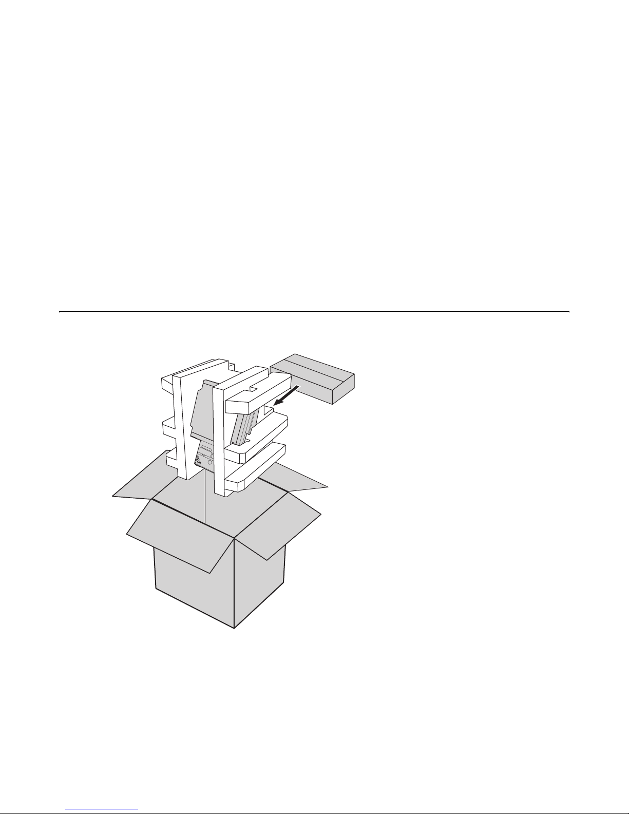
The PT-8800 and cable accessories are packed in a cardboard carton with foam padding for protection during shipping.
Figure 1.1 Unpacking the PT-8800
Carefully unpack the PT-8800 and keep the packing materials. If you need to ship the PT-8800 in the future, repack it
as shown in Figure 1.1.
1
Page 10

Checking the package contents
After you unpack the PT-8800 check that the following items are included.
PT-8800 (SOME UNITS SHIP WITH CUSTOMER
DISPLAY AND MSR INSTALLED)
MSR (OPTIONAL)CUSTOMER DISPLAY
(
OPTIONAL)
ECOND DISPLAY (OPTIONAL)(THIS) USER MANUAL
S
OWER CABLE DRIVER CD-ROM WITH
P
If any item is missing or appears damaged, contact your dealer immediately.
DRIVERS AND USER MANUAL
PDF
PT-8800
2 Chapter 1 Getting Started
Page 11
Identifying components
This section describes the parts and connectors on the PT-8800.
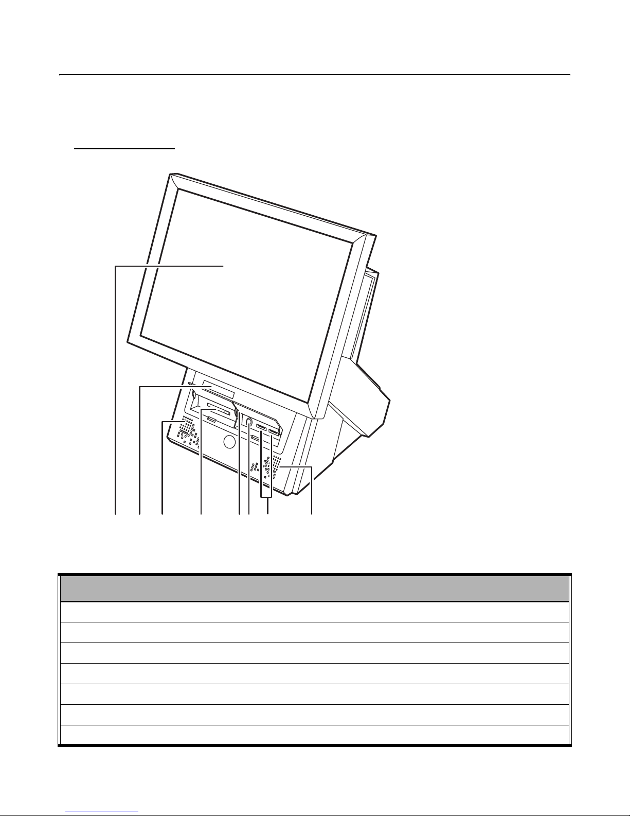
Front-right view
324675 31
Figure 1.2 Front-right view of PT-8800
1 15-inch TFT LCD touch screen
2 Smart card reader
3 Speakers
4 Compact Flash card reader
5 Power LED
6 Power button
7 Two USB ports
DESCRIPTION
Identifying components 3
Page 12
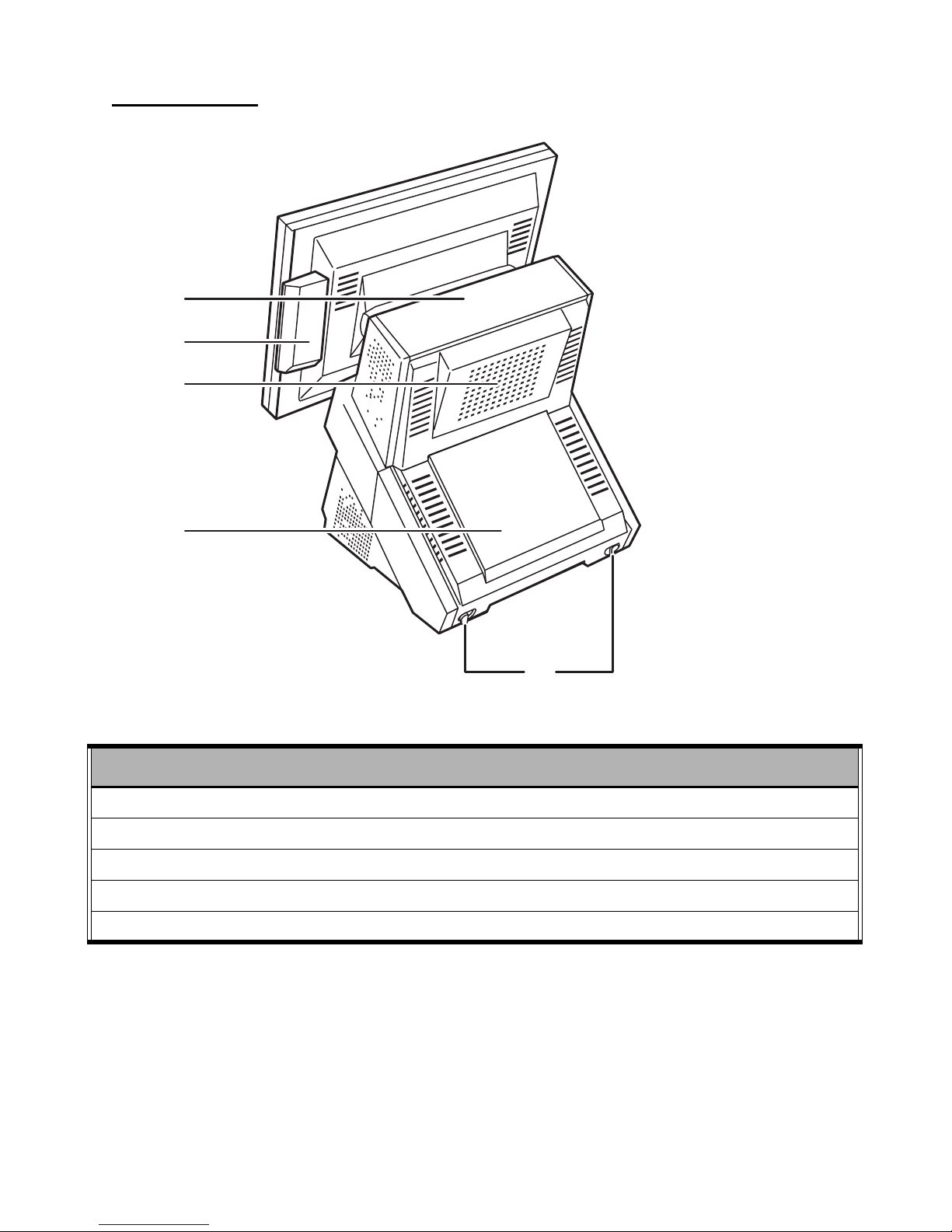
Rear-right view
1
2
3
4
Figure 1.3 Rear-right view of PT-8800
1 Customer display cover
2MSR module
3 Mainboard cover
4 Rear cover
5 Rear cover latches
5
DESCRIPTION
4 Chapter 1 Getting Started
Page 13
Rear connectors
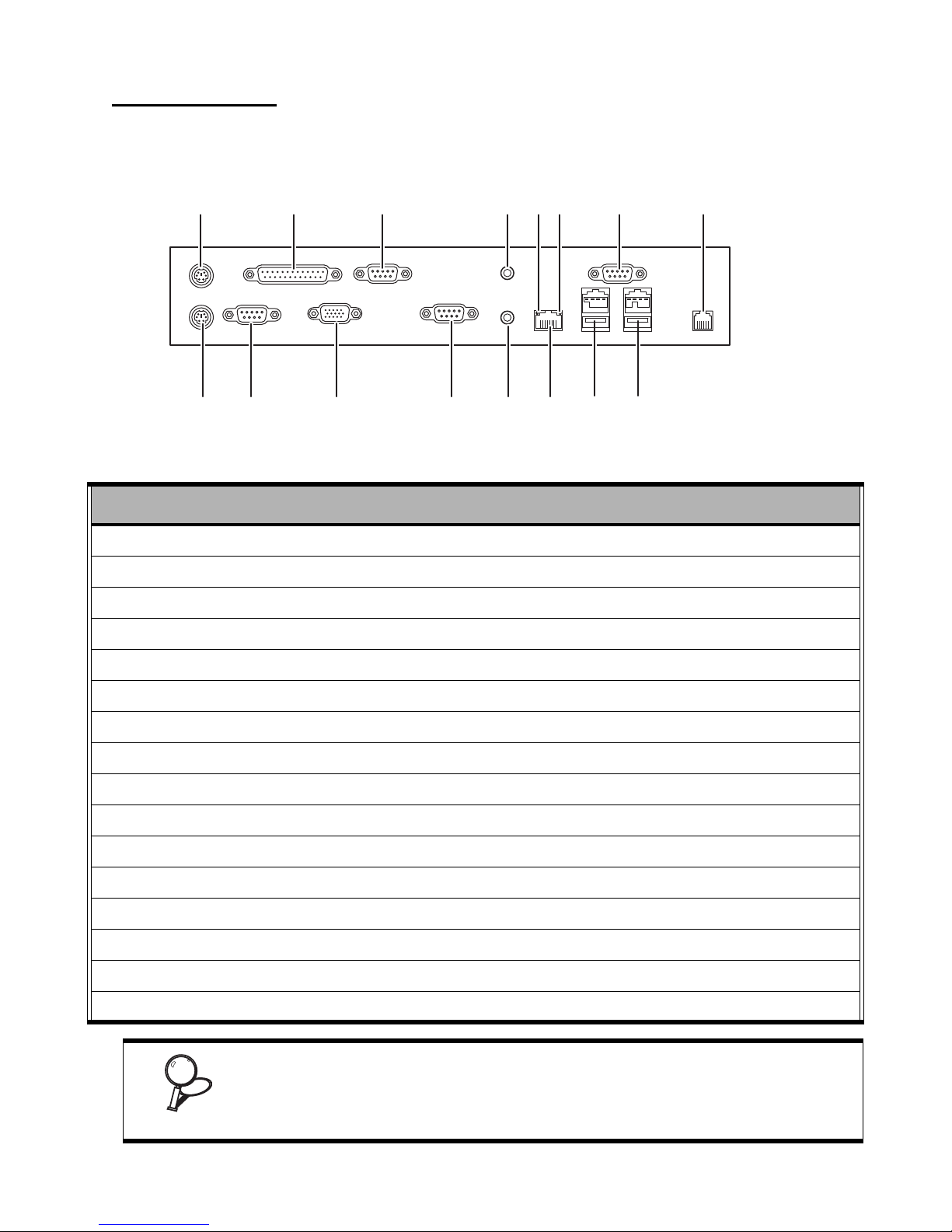
Figure 1.4 shows the connectors on the rear of the PT-8800. You must remove the rear cover to access the connectors.
See “Removing the rear cover” on page 6.
1516
Figure 1.4 Rear connectors labeled
1 PS/2 mouse connector
2 Parallel connector
3 COM4 connector
4 Line out
3145627
1014 13 12 11
9
8
DESCRIPTION
5 Act LED (green) lights when network activity is detected
6 Link LED (orange) lights when the network is found
7 COM2 connector
8 RJ-11 cash drawer connector
9 Powered USB connector (24V) - connect peripherals such as USB printers
10 Powered USB connector (12V) - connect peripherals such as a customer display
11 RJ-45 (LAN) connector
12 Mic in
13 COM3 connector
14 VGA connector
15 COM1 connector
16 PS/2 keyboard connector
Powered USB peripherals have keyed connectors to match the 12V and 24V
powered USB connectors on the PT-8800. Do not try to force a 12V connector
from a peripheral into the 24V connector on the PT-8800.
IMPORTANT
You can also connect standard USB devices to the powered USB connectors.
Identifying components 5
Page 14
For powered USB:
1. 24V cannot exceed 2A
2. 12V cannot exceed 3A
IMPORTANT
3. Total of 24V & 12V cannot exceed 48 watts.
Plugging a phone line into the LAN port (RJ-45 connector) can damage the connector. Take care to only plug an RJ-45 connector into the LAN port.
CAUTION
COM 6 is reserved for the optional customer display.
NOTE
Removing the rear cover
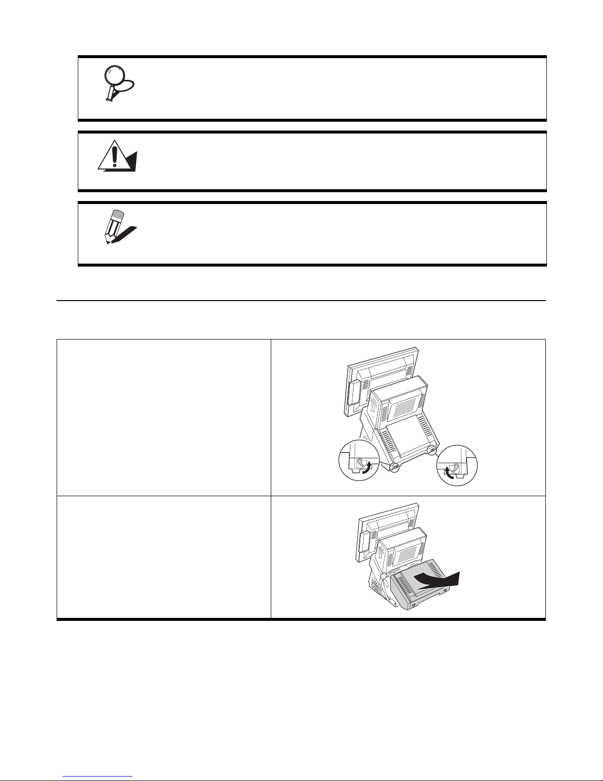
Refer to the following to remove the rear cover.
1 Open the rear cover latches.
2 Remove the rear cover.
6 Chapter 1 Getting Started
Page 15
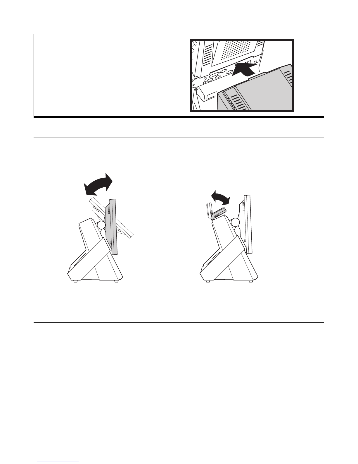
When replacing:
Align the rear cover tab with the opening on the PT-8800.
Adjusting display angles
The main display can be tilted back from an upright perpendicular position to about 30 degrees as shown in Figure 1.5.
The customer display can be tilted as shown in Figure 1.6.
Figure 1.5 Adjusting the display Figure 1.6 Adjusting the customer display
Setup considerations
When setting up the PT-8800, consider the following:
• Use a desktop or counter that is stable and even.
• Ensure there is enough room around the sides and rear of the PT-8800 for ventilation.
• Ensure there is room to connect cables and that cables are long enough to reach peripheral devices or a power
outlet.
Adjusting display angles 7
Page 16
Connecting peripheral devices
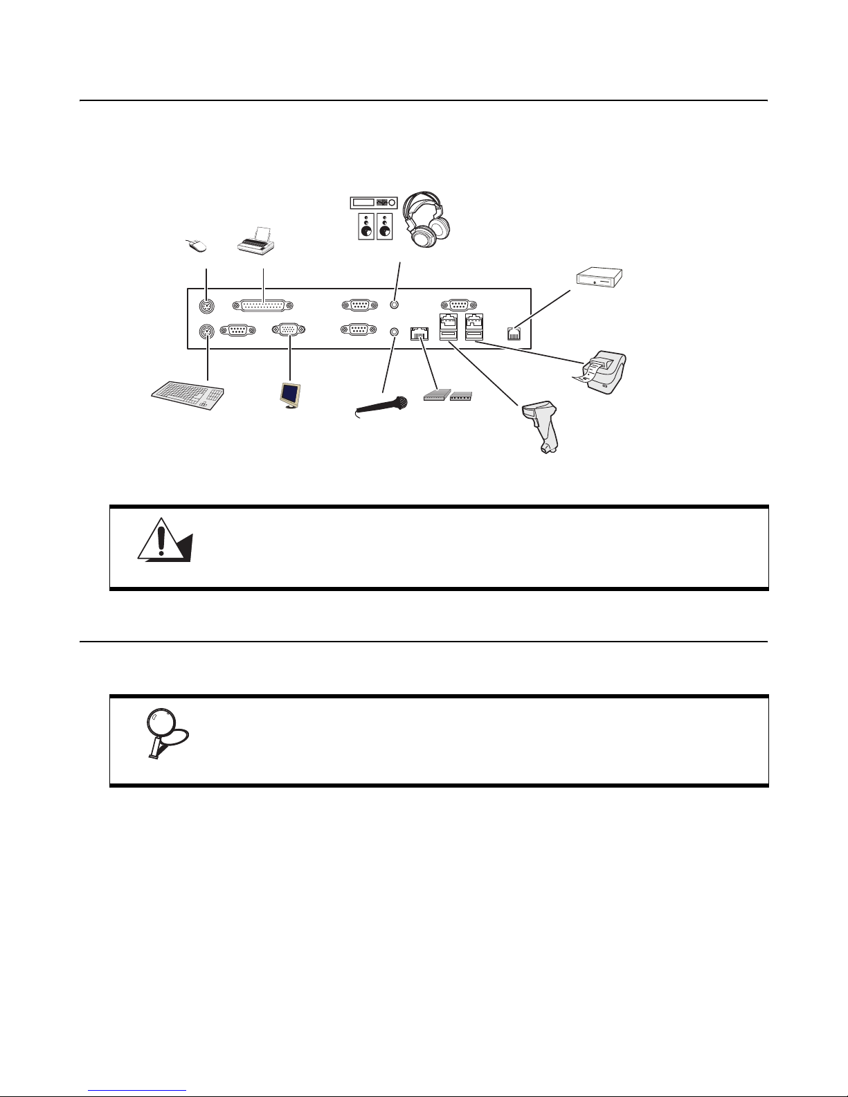
Peripheral devices such as a printer or scanner can be connected to the PT-8800. Refer to the user manual of the device
you are connecting for instructions on installing drivers where needed. (Remove the rear cover to access the connectors. See “Removing the rear cover” on page 6.)
Mouse
Keyboard
Printer
COM1 COM3
Monitor
Figure 1.7 Connecting peripheral devices
Do not plug a phone line into the RJ-45 (ADSL or router) connector. Doing so can
damage the connector.
CAUTION
Connecting a cash drawer
Amplifier or
speakers
COM4 COM2
Microphone
Headphones
s
p
b
800
8
2
MR HSAA CD OHSD RD TR
ADSL modem
or router
Cashdrawer
Powered USB
Compliant
devices (24V)
Powered USB
Compliant
devices (12V)
Refer to the following to connect a cash drawer.
The cash drawer RJ-11 connector is DC+24V. Ensure the cash drawer to be connected matches this power specification.
IMPORTANT
1 Remove the rear cover. (See “Removing the rear cover” on page 6.)
2 Connect the RJ-11 cable from the cash drawer to the RJ-11 connector on the PT-8800.
8 Chapter 1 Getting Started
Page 17
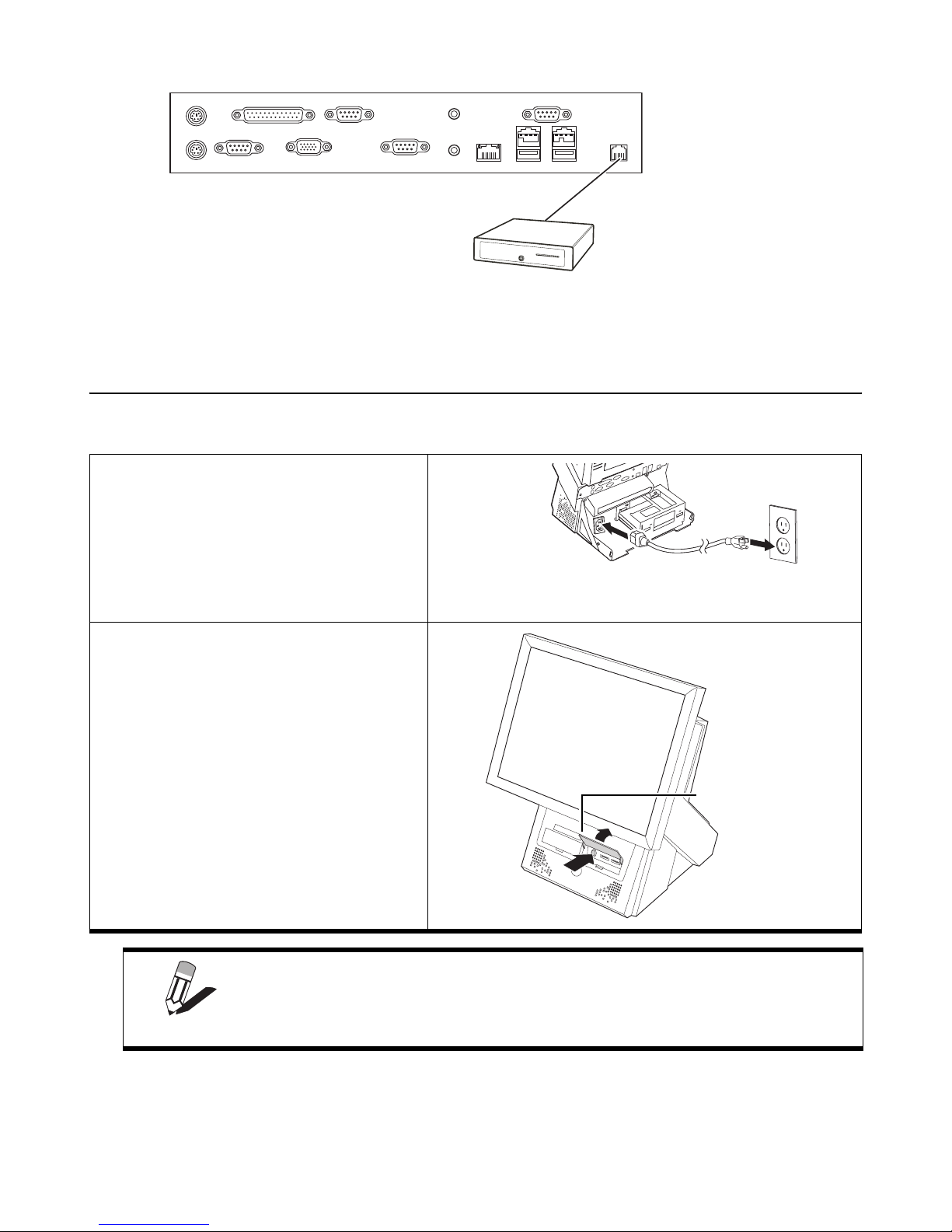
Cashdrawer
3 Turn on the PT-8800. (See “Powering the PT-8800 on and off” below.)
Powering the PT-8800 on and off
Refer to the following to power on and off the PT-8800.
1 Remove the rear cover. See “Removing the
rear cover” on page 6.
2 Connect the power cable to the power con-
nector on the PT-8800 and to an electrical
outlet.
3 Lift the cover.
4 Press the power button.
The power LED turns on.
5 To turn off the PT-8800, shut down the
operating system: the main power turns off
automatically.
You may need to use the power button to turn off the power, for example if the
operating system you are using does not support power down by the OS or if the
NOTE
system crashes or hangs.
Power LED
Powering the PT-8800 on and off 9
Page 18

10 Chapter 1 Getting Started
Page 19
CHAPTER 2
U
PGRADING COMPONENTS
This chapter describes how to upgrade components for the PT-8800. The following topics are described.
• “Safety and precautions”
• “Before you begin” on page 12
• “Installing a hard disk drive (HDD)” on page 12
• “Installing optional displays” on page 13
• “Installing a CompactFlash card” on page 17
• “Installing a PCI card” on page 18
Safety and precautions
Computer components and electronic circuit boards can be damaged by discharges of static electricity. Working on
computers that are still connected to a power supply can be extremely dangerous. Follow these guidelines to avoid
damage to the computer or injury to yourself.
• Always disconnect the unit from the power outlet.
• Leave all components inside the static-proof packaging that they ship with until they are ready for installation.
• After replacing optional devices, make sure all screws, springs, or other small parts are in place and are not left
loose inside the case. Metallic parts or metal flakes can cause electrical shorts.
Only qualified personnel should perform repairs on the PT-8800. Damage due to
unauthorized servicing is not covered by the warranty. If you are not confident of
carrying out installation procedures, we recommend that you refer the job to
CAUTION
qualified personnel.
If the LCD breaks and fluid gets onto your hands or into your eyes, immediately
wash with water and seek medical attention.
WARNING
The inverter card has high voltage. Do not touch the inverter card while power is
connected to the PT-8800. Unplug the power cord before attempting to replace
WARNING
CAUTION
any part.
To prevent static damage to components, wear a grounded wrist strap. Alternatively, discharge any static electricity by touching the bare metal chassis of the
unit case, or the bare metal body of any other grounded appliance.
11
Page 20
Hold electronic circuit boards by the edges only. Do not touch the components
on the board unless it is necessary to do so. Do not flex or stress the circuit
board. Do not hold components such as a processor by its pins; hold it by the
CAUTION
edges.
Before you begin
Make sure you have a stable, clean working environment. Dust and dirt can get into components and cause a malfunction. Adequate lighting and proper tools can prevent you from accidentally damaging the internal components.
Most of the electrical and mechanical connections can be disconnected by using your fingers. It is recommended that
you do not use needle-nosed pliers to disconnect connectors as these can damage the soft metal or plastic parts of the
connectors.
To prevent scratching the case of the PT-8800, make sure the worktop surface is
clean and flat.
CAUTION
Installing a hard disk drive (HDD)
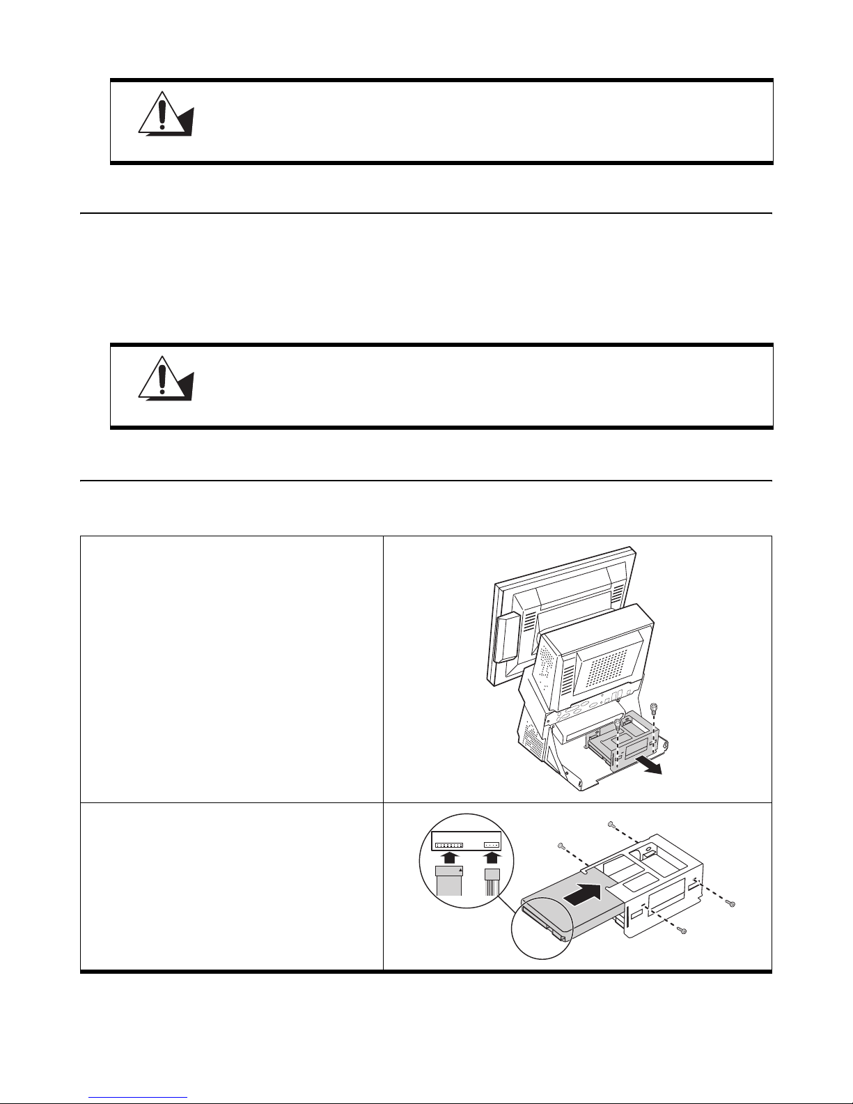
Refer to the following to install a HDD.
1 Remove the rear cover. See “Removing the
rear cover” on page 6.
2 Remove the two thumbscrews.
3 Remove the hard drive bracket.
4 Place the new hard drive in the bracket.
5 Secure the hard drive with four screws.
6 Connect the two cables.
7 Replace the hard drive bracket.
8 Replace the two thumbscrews.
12 Chapter 2 Upgrading Components
Page 21
Refer to the documentation with the hard drive for instructions on setting drive
jumpers and formatting the drive.
NOTE
Installing optional displays
The PT-8800 may ship with a customer display attached or you can order one and install it. An optional second display
can also be installed. Before installing the optional displays you must remove the mainboard cover and the top rear
cover.
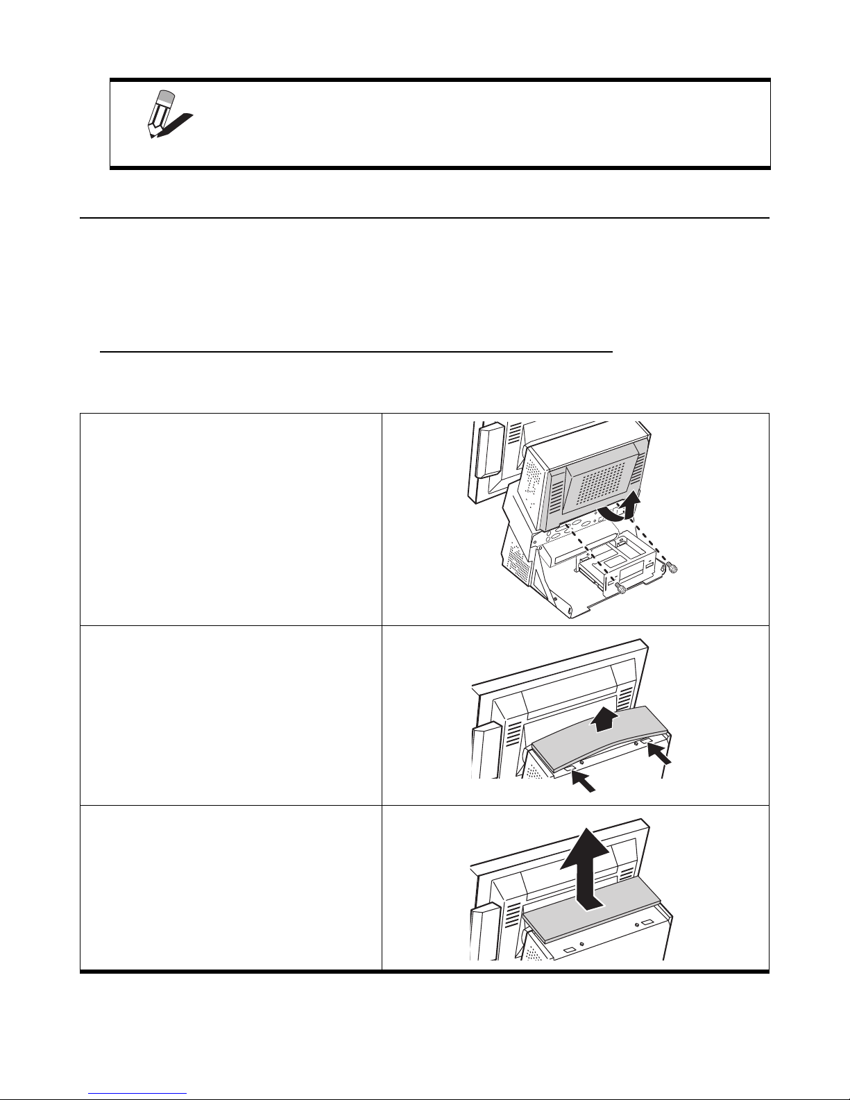
Removing the mainboard cover and customer display cover
Refer to the following to remove the rear cover.
1 Remove the two thumbscrews.
2 Remove the mainboard cover.
3 Bow the cover up slightly to release the two
tabs.
4 Remove the customer display cover.
Installing optional displays 13
Page 22
When replacing:
Align the customer display cover tabs
with the openings on the PT-8800.
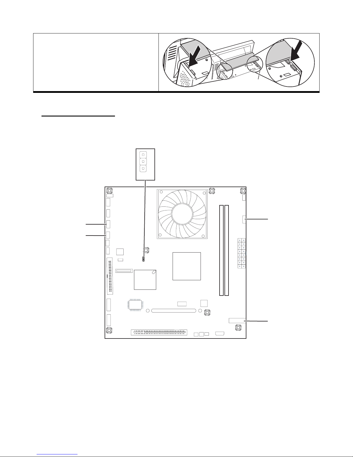
Mainboard reference
When connecting the displays, refer to the following for connector locations on the mainboard.
3
2
1
JP2
CN14
CN24
CN23
CN15
14 Chapter 2 Upgrading Components
Page 23
Attaching the customer display
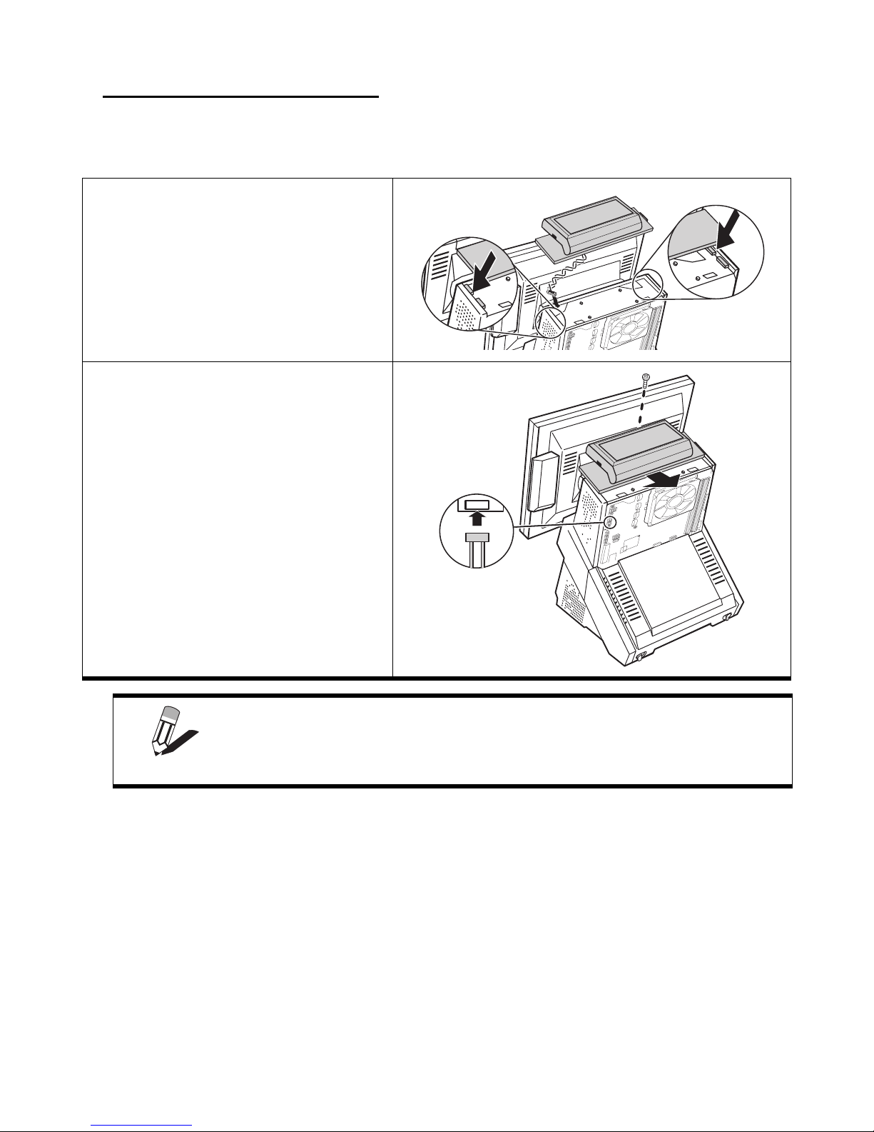
The PT-8800 may ship with a customer display attached. If you ordered the display separately, refer to the following to
attach it.
1 Pass the cable through the opening in the
PT-8800.
2 Align the tabs on the customer display with
the openings on the PT-8800.
3 Slide the customer display into place.
4 Connect the customer display cable to
CN14. See “Mainboard reference” on
page 14.
5 Secure the display with the supplied screw.
6 Replace the mainboard cover.
To supply power to the customer display, the COM6 voltage is factory set to
DC+12V.
NOTE
Installing optional displays 15
Page 24
Attaching the second display
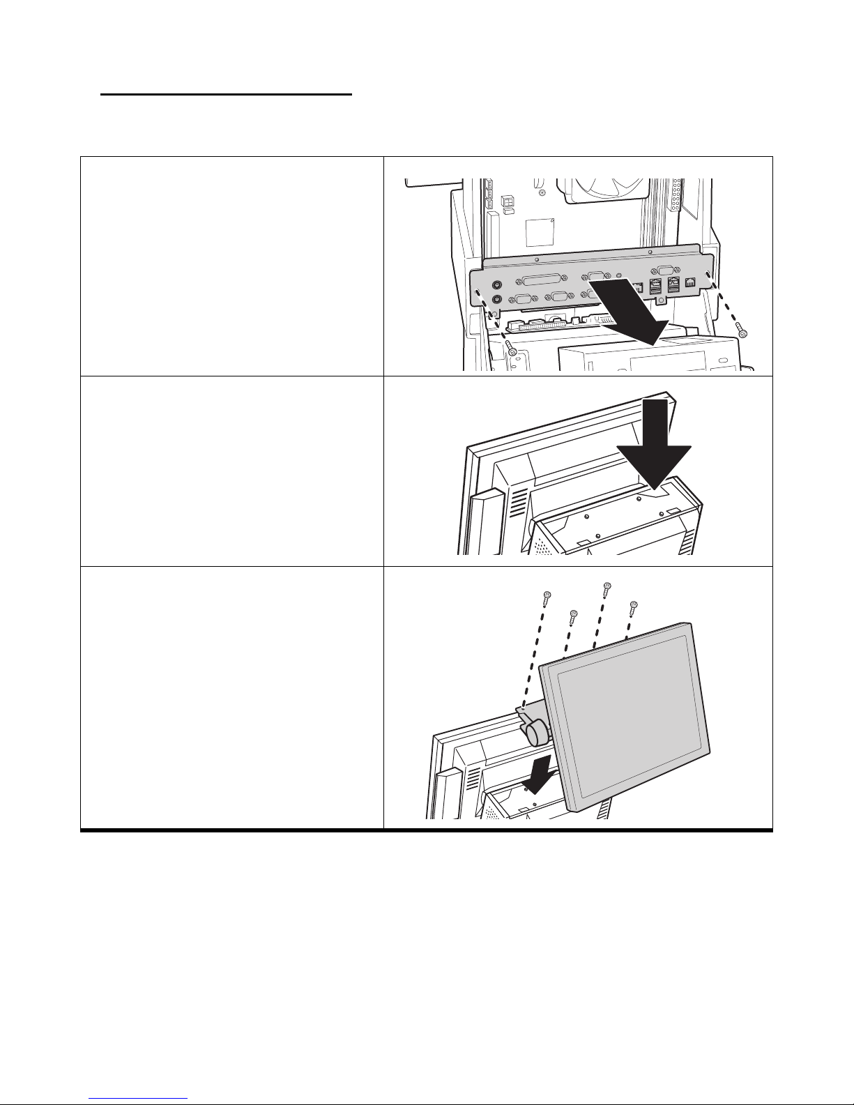
Refer to the following to attach the second display
1 Remove the two thumbscrews.
2 Remove the I/O board.
3 Pass the diplay cables through the indicated
opening.
4 Secure the display bracket with the four
supplied screws.
16 Chapter 2 Upgrading Components
Page 25
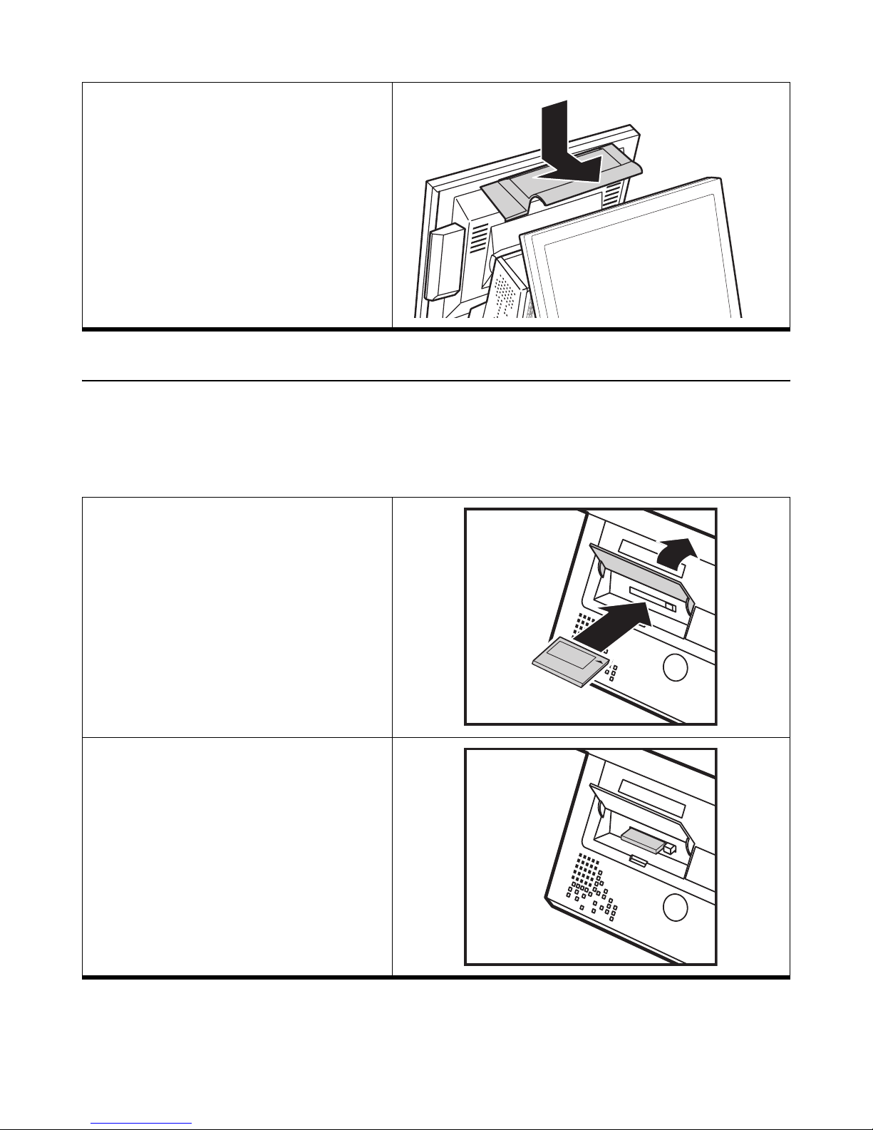
5 Put the bracket cover on.
6 Plug in the two cables to CN15 and CN23.
See “Mainboard reference” on page 14.
7 Replace the I/O board.
8 Replace the mainboard cover.
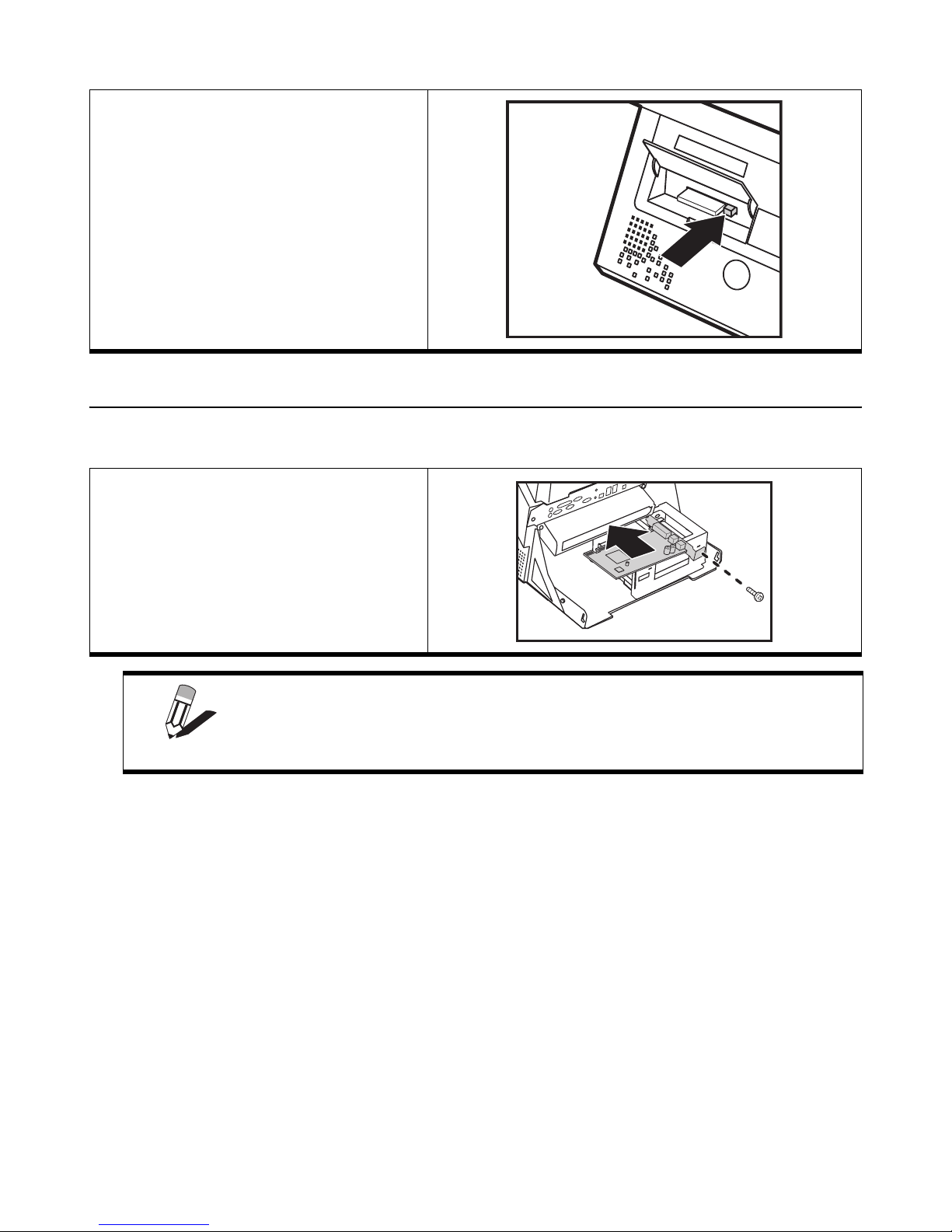
Installing a CompactFlash card
The CompactFlash card reader uses an IDE (Integrated Drive Electronics) interface and only supports storage cards.
Plug and play is not supported so cards have to be installed before you turn the PT-8800 on. After installing a CompactFlash card, close the cover to prevent the card being accidently removed while power is on.
Refer to the following to install a CompactFlash card.
1 Use a thin plastic spatula to lift the cover.
(To prevent unauthorized removal of a card,
the cover is designed not to open easily.)
2 Insert the CompactFlash card as shown.
Caution: Inserting the card incorrectly can
damage the connector pins. Ensure the card
is oriented as shown and insert it gently.
Note that a properly installed card still protrudes
as shown here.
Installing a CompactFlash card 17
Page 26
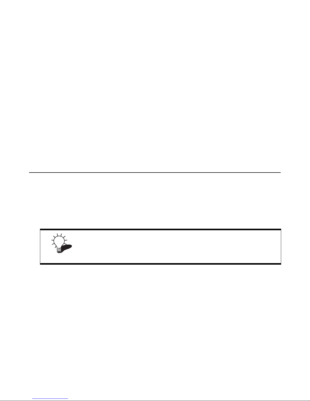
3 To remove a card press the eject button and
pull the card out.
Installing a PCI card
Refer to the following to install a PCI card.
1 Remove the rear cover. See “Removing the
rear cover” on page 6.
2 Insert the PCI card.
3 Secure the card with one screw.
Ensure there are no cables preventing the PCI card from connecting to the mainboard.
NOTE
18 Chapter 2 Upgrading Components
Page 27
CHAPTER 3
BIOS S
The BIOS (Basic Input and Output System) Setup Utility displays the system's configuration status and provides
options to set system parameters. The parameters are stored in battery-backed-up CMOS RAM that saves this information even when the power is turned off. When the system is turned back on, the system is configured with the values
found in CMOS. The following topics are described in this chapter.
• “About the Setup Utility”
• “Entering the Setup Utility” on page 20
• “Standard CMOS Features” on page 21
• “Advanced BIOS Features ” on page 24
• “Integrated Peripherals ” on page 28
• “Power Management Setup Option” on page 32
• “PnP/PCI Configurations” on page 35
• “Frequency/Voltage Control Option” on page 37
• “Other BIOS Options” on page 38
ETUP UTILITY
About the Setup Utility
The BIOS Setup Utility enables you to configure the following items:
• Hard drives, diskette drives, and peripherals
• Video display type and display options
• Password protection from unauthorized use
• Power management features
If you have made settings that you do not want to save, use the "Exit Without
Saving" item and press Y to discard any changes you have made.
TIP
This Setup Utility should be used for the following:
• When changing the system configuration
• When a configuration error is detected and you are prompted to make changes to the Setup Utility
• When trying to resolve IRQ conflicts
• When making changes to the Power Management configuration
• When changing the User or Supervisor password
19
Page 28
Entering the Setup Utility
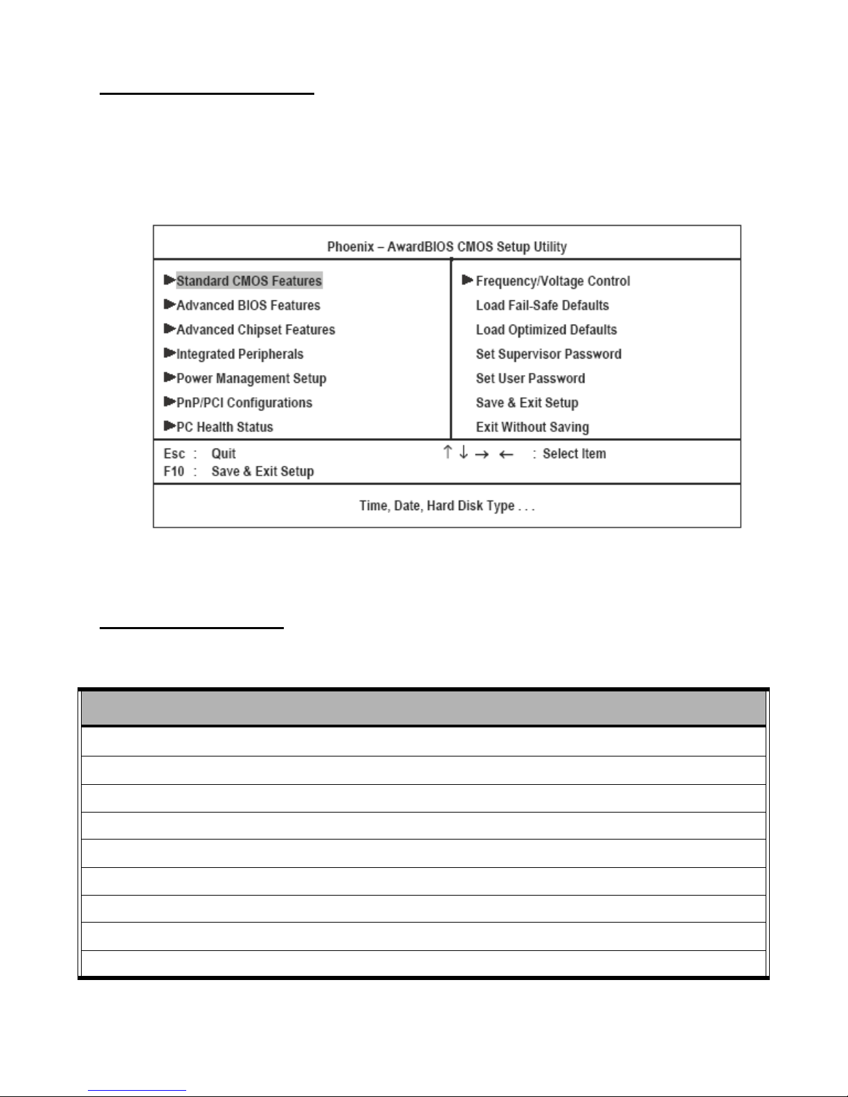
When you power on the system, BIOS enters the Power-On Self Test (POST) routines. POST is a series of built-in
diagnostics performed by the BIOS. After the POST routines are completed, the following message appears:
Press DEL to enter SETUP
Press the delete key <Delete> to access the Award BIOS Setup Utility:
Figure 3.1 Main BIOS menu
BIOS navigation keys
The BIOS navigation keys are listed below.
KEY FUNCTION
←↑↓→
+/–/PU/PD Modifies the selected field's values
Esc Exits the current menu
F1 Displays a screen that describes all key functions
F5 Loads previously saved values to CMOS
F6 Loads a minimum configuration for troubleshooting
F7 Loads an optimum set of values for peak performance
F10 Saves the current configuration and exits Setup
Scrolls through the items on a menu
Shift + F2 Changes the color of the BIOS menu
20 Chapter 3 BIOS Setup Utility
Page 29
Using BIOS
When you start the Setup Utility, the main menu appears. The main menu of the Setup Utility displays a list of the
options that are available. A highlight indicates which option is currently selected. Use the cursor arrow keys to move
the highlight to other options. When an option is highlighted, execute the option by pressing <Enter>.
Some options lead to pop-up dialog boxes that prompt you to verify that you wish to execute that option. Other options
lead to dialog boxes that prompt you for information.
Some options (marked with a triangle ) lead to submenus that enable you to change the values for the option. Use
the cursor arrow keys to scroll through the items in the submenu.
Standard CMOS Features
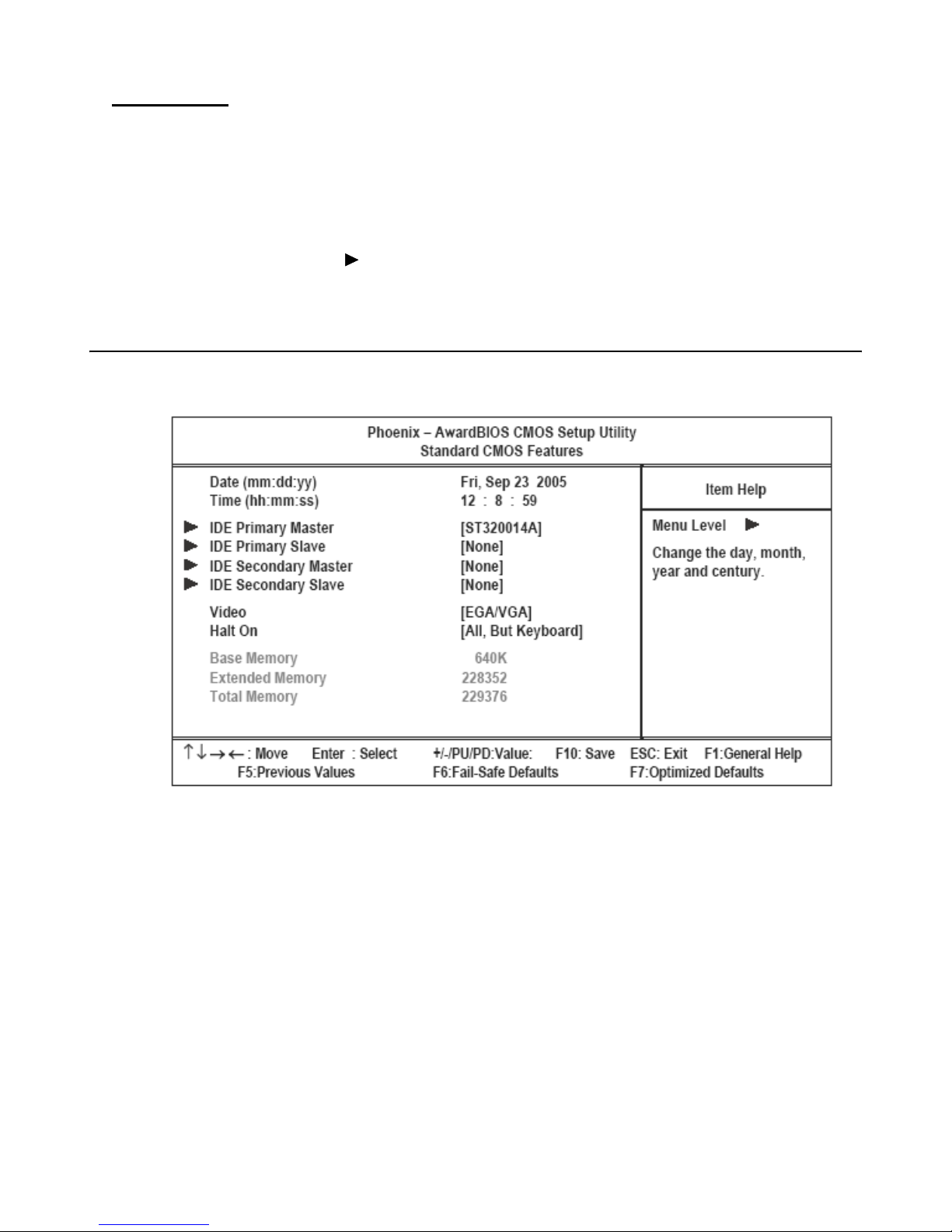
Selecting Standard CMOS Features on the main menu displays the following menu:
Figure 3.2 Standard CMOS Features menu
Date and Time
The Date and Time items show the current date and time held by your PT-8800. If you are running a Windows OS,
these items are automatically updated whenever you make changes to the Windows Date and Time Properties utility.
Standard CMOS Features 21
Page 30
IDE Primary/Secondary Master/Slave
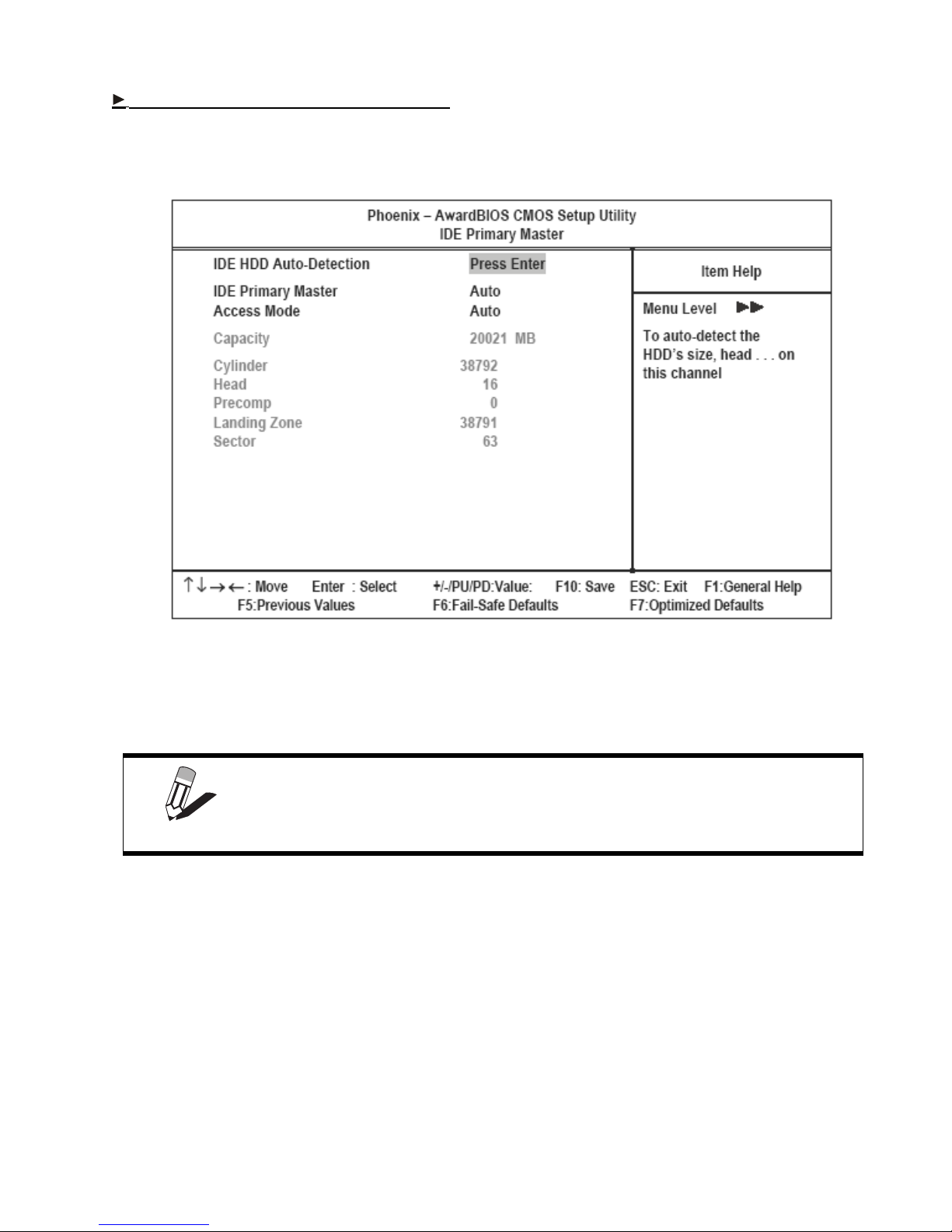
This field is used to configure the IDE hard drive installed in the system. Move the cursor to highlight the IDE Primary/Secondary Master/Slave fields and press <Enter>. The IDE Primary Master submenu opens:
Figure 3.3 IDE Primary Master Submenu
IDE HDD Auto-Detection
Press Enter while this item is highlighted if you want the Setup Utility to automatically detect and configure a hard
disk drive on the IDE channel.
If you are setting up a new hard disk drive that supports LBA mode, more than
one line will appear in the parameter box. Choose the line that lists LBA for an
NOTE
IDE Primary/Secondary Master/Slave
LBA drive.
If you leave this item at Auto, the system will automatically detect and configure any IDE devices it finds. If it fails to
find a hard disk, change the value to Manual and then manually configure the drive by entering the characteristics of
the drive in the fields described below:
• Capacity – displays the capacity of the HDD in megabytes (M).
• Cylinder – indicates the number of cylinders that the HDD has. A cylinder is the sum total of all tracks that are
in the same location on every disk surface.
• Head – displays the number of heads in the HDD. A head is a device that reads and writes data on the hard
disk.
• Precomp – displays the track where precompensation is initiated. Precompensation is a feature whereby the
HDD uses a stronger magnetic field to write data in sectors that are closer to the center of the disk. In CAV
22 Chapter 3 BIOS Setup Utility
Page 31

recording, in which the disk spins at a constant speed, the sectors closest to the spindle are packed tighter than
the outer sectors.
• Landing Zone – displays the location of the safe non-data area on a hard disk that is used for parking the read/
write head.
• Sector – displays the number of sectors available on the HDD. A sector is the smallest unit of storage space on
a disk.
Access Mode
This item defines special ways that can be used to access IDE hard disks such as LBA (Large Block Addressing).
Leave this value at Auto and the system will automatically decide the fastest way to access the hard disk drive.
Press <Esc> to close the IDE device menu and return to the Standard CMOS Features menu.
Video (EGA/VGA)
This item defines the video mode of the system. This mainboard has a built-in VGA graphics system; you must leave
this item at the default setting.
Halt On (All, But Keyboard)
This item defines the operation of the system POST (Power On Self Test) routine. You can use this item to select which
types of errors in the POST are sufficient to halt the system.
Base Memory, Extended Memory, and Total Memory
These items are automatically detected by the system at start up time. These are display-only fields. You cannot make
changes to these fields.
• Base Memory – This field displays the amount of conventional memory detected by the system during boot.
• Extended Memory – This field displays the amount of extended memory detected by the system during boot.
• Tot a l M e mo ry – This field displays the total amount of memory (Base and Extended) detected by the system
during boot.
Press <Esc> to return to the main menu.
Standard CMOS Features 23
Page 32
Advanced BIOS Features
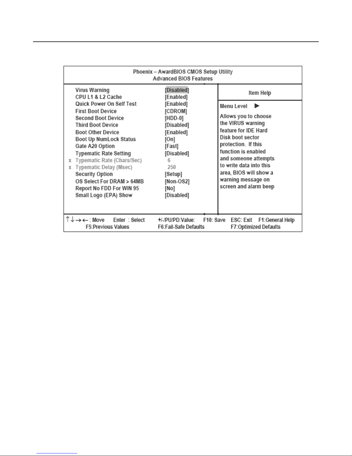
Selecting Advanced BIOS Features on the menu displays this menu:
Figure 3.4 Advanced BIOS Features menu
Virus Warning
When enabled, this item provides protection against viruses that try to write to the boot sector and partition table of
your hard disk drive. You need to disable this item when installing an operating system. We recommend that you
enable anti-virus protection as soon as you have installed an operating system. The default setting is Disabled.
CPU L1 & L2 Cache
Most processors that can be installed in this mainboard use internal level 1 (L1) and level 2 (L2) cache memory to
improve performance. Leave this item at the default setting for better performance. The default setting is Enabled.
Quick Power On Self Test
Enable this item to shorten the power on testing (POST) and have your system start up faster. You can enable this item
after you are confident that your system hardware is operating smoothly. The default setting is Fast.
First/Second/Third Boot Device
The BIOS loads the operating system from the disk drives in the sequence selected in these three fields. The default
setting is Floppy/CD-ROM/HDD0.
Boot Other Device
When enabled, the system searches all other possible locations for an operating system if it fails to find one in the
devices specified under the First, Second, and Third boot devices. The default setting is Enabled.
Boot Up NumLock Status
This item defines if the keyboard Num Lock key is active when your system is started. The default setting is On.
24 Chapter 3 BIOS Setup Utility
Page 33

Gate A20 Option
This item defines how the system handles legacy software that was written for an earlier generation of processors.
Leave this item at the default setting. The default setting is Fast.
Typematic Rate Setting
If this item is enabled, you can use the following two items to set the typematic rate and the typematic delay settings
for your keyboard. The default setting is Disabled.
Typematic Rate (Chars/Sec)
Use this item to define how many characters per second are generated by a held-down key. The default setting is 6.
Typematic Delay (Msec)
Use this item to define how many milliseconds elapse before a held-down key begins generating repeat characters. The
default setting is 250.
Security Option
If you have installed password protection, this item defines if the password is required at system start up, or if it is only
required when a user tries to enter the Setup Utility. The default setting is Setup.
OS Select For DRAM > 64 MB
This item is only required if you have installed more than 64 MB of memory and you are running the OS/2 operating
system. Otherwise, leave this item at the default. The default setting is Non-OS2.
Report No FDD For WIN 95
If you are running a system with no floppy drive and using Windows 95, select Yes for this item to ensure compatibility with the Windows 95 logo certification. Otherwise, select No. The default setting is No.
Small Logo (EPA) Show
Determines whether the EPA logo appears during boot up. The default setting is Enabled.
Press <Esc> to return to the main menu.
Advanced BIOS Features 25
Page 34
Advanced Chipset Features
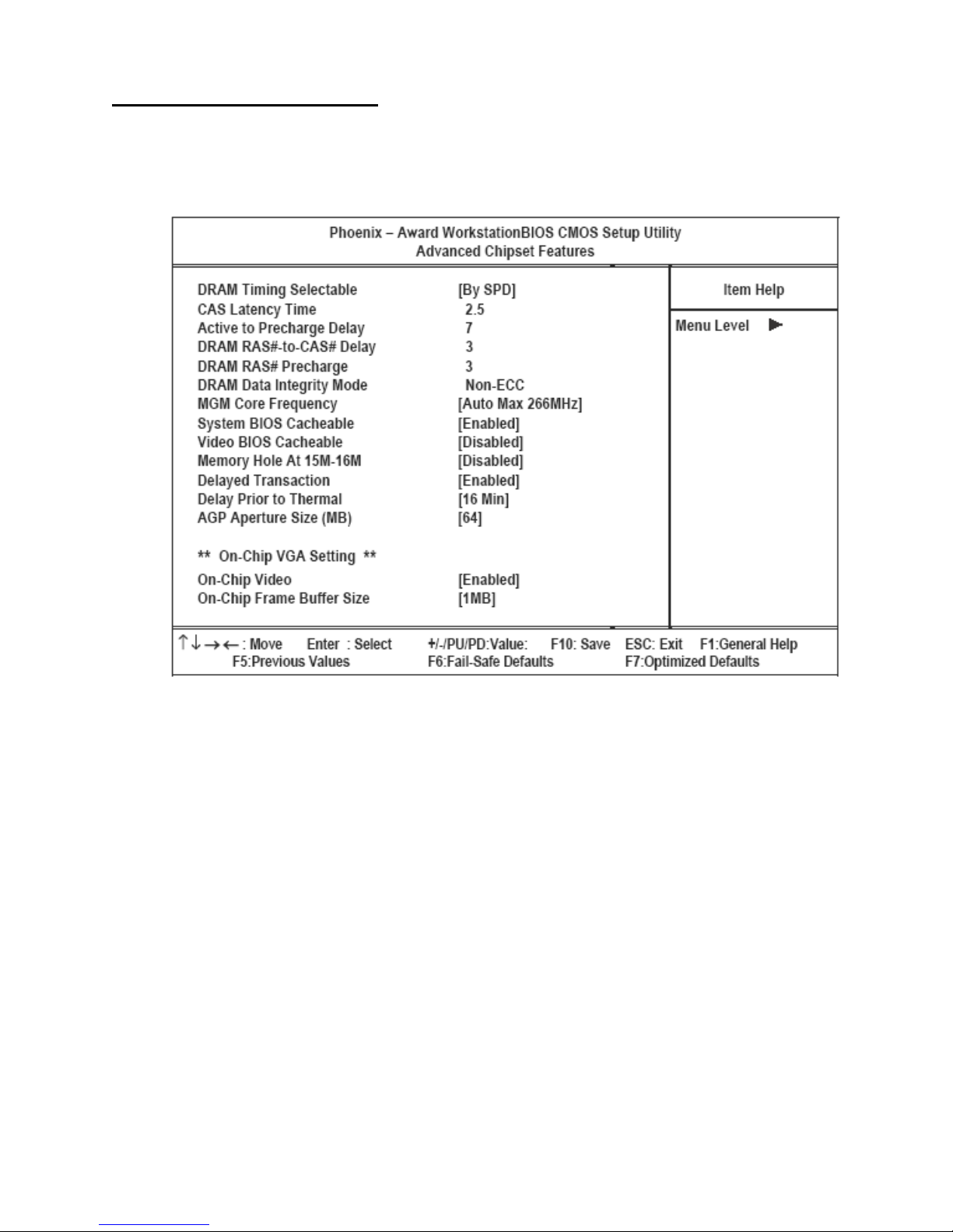
This option displays critical timing parameters of the mainboard. Leave the items on this menu at their default settings
unless you are very familiar with the technical specifications of your system hardware. If you change the values incorrectly, you may introduce fatal errors or recurring instability into your system.
Figure 3.5 Advanced Chipset Features menu
DRAM Timing Selectable
The EEPROM on a memory card has Serial Presence Detect (SPD) data structure that stores information about the
module such as memory size and speed. When SPD is selected, the “CAS Latency Time” and “Active to Precharge
Delay” items are set to their defaults, and the system runs according to information in the EEPROM providing the
most stable condition. The default setting is SPD.
CAS Latency Time
This item enables you to specify the time delay (in clock cycles or CLKs) that elapses before the SDRAM carries out a
read command after receiving it. The value specified here also sets the number of CLKs that will elapse for the completion of the first part of a burst transfer. Low values indicate a faster data transaction. When synchronous DRAM is
installed, the number of clock cycles of CAS latency depends on the DRAM timing. The default is 2.5.
Active to Precharge Delay
To change the active-to-precharge delay, the “DRAM Timing Selectable” setting must be set to User. The default set-
ting is 7.
DRAM RAS# to CAS# Delay
This item enables you to set the time it takes data to move between the Row Address Strobe (RAS) and Column
Address Strobe (CAS). You can also insert a timing delay between RAS and CAS. When set to higher values, reads,
writes, and refreshes take longer, but data is transferred with better reliability. The default setting is Auto.
26 Chapter 3 BIOS Setup Utility
Page 35

DRAM RAS# Precharge Time
DRAM must continually be refreshed or it will lose its data. Normally, DRAM is refreshed entirely as the result of a
single request. This option allows you to determine the number of CPU clocks allocated for the Row Address Strobe
(RAS) to accumulate its charge before the DRAM is refreshed. If insufficient time is allowed, refresh may be incomplete and data lost. The default setting is Auto.
DRAM Data Integrity Mode
Set the DRAM Data Integrity Mode. The default setting is NON-ECC.
MGM Core Frequency
Set the MGM Core Frequency. The default setting is AUTO MAX266.
System/Video BIOS Cacheable
These items allow the video and/or system to be cached in memory for faster execution. We recommend that you leave
these items at the default value. The default setting is Disabled.
Memory Hole at 15M-16M
This item can be used to reserve memory space for some ISA expansion cards that require it. The default setting is Disabled.
Delayed Transaction
The chipset has an embedded 32-bit posted write buffer to support delay transactions cycles. Enable this item to support compliance with PCI specification version 2.1. The default setting is Enabled.
Delay Prior to Thermal
Set the Delay Prior to Thermal. The default setting is 16 min.
AGP Aperture Size (MB)
This item defines the size of the aperture if you use an AGP graphics adapter. The AGP aperture refers to a section of
the PCI memory address range used for graphics memory. We recommend that you leave this item at the default setting. The default setting is 64.
On-Chip Video
This item is used to enable or disable the onboard video. The default setting is Enabled.
On-Chip Frame Buffer Size
This item is used to select the video frame buffer size. The default setting is 1MB.
After you have made your selections in the Advanced Chipset Features menu, press <ESC> to go back to the main
menu.
Advanced BIOS Features 27
Page 36
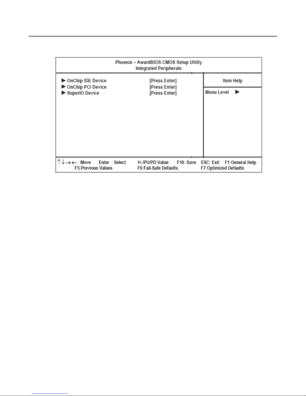
Integrated Peripherals
This option defines the operation of peripheral components on the system's input/output ports.
Figure 3.6 Integrated Peripherals menu
OnChip IDE Device (See “OnChip IDE Device” on page 29.)
OnChip PCI Device (See “Onboard Device” on page 30.)
SuperIO Device (See “SuperIO Device” on page 31.)
28 Chapter 3 BIOS Setup Utility
Page 37
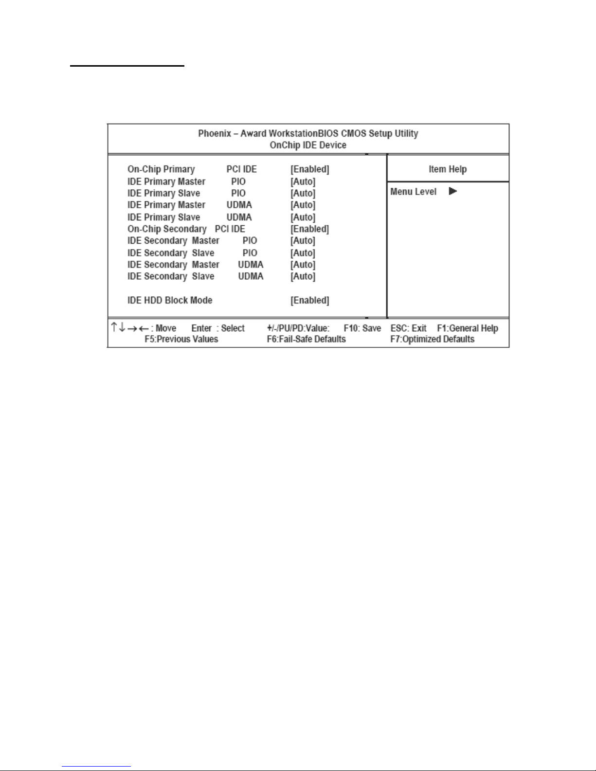
OnChip IDE Device
Use this item to enable or disable the PCI IDE channels that are integrated on the mainboard. Select the item and press
<Enter> to open the following menu:
Figure 3.7 OnChip IDE Device menu
On-Chip Primary/Secondary PCI/IDE
Use this item to enable or disable the PCI IDE channels that are integrated on the mainboard. The default setting is
Enabled.
IDE Primary/Secondary Master/Slave PIO
Each IDE channel supports a master device and a slave device. These four items let you assign which kind of PIO
(Programmed Input/Output) is used by IDE devices. Choose Auto to let the system auto detect which PIO mode is
best, or select a PIO mode from 0-4. The default setting is Auto.
Primary/Secondary Master/Slave UltraDMA
Each IDE channel supports a master device and a slave device. This mainboard supports UltraDMA technology, which
provides faster access to IDE devices. If you install a device that supports UltraDMA, change the appropriate item on
this list to Auto. You may have to install the UltraDMA driver supplied with this mainboard in order to use an
UltraDMA device. The default setting is Auto.
IDE HDD Block Mode
Enable this field if your IDE hard drive supports block mode. Block mode enables BIOS to automatically detect the
optimal number of block read and writes per sector that the drive can support and improves the speed of access to IDE
devices. The default setting is Enabled.
Integrated Peripherals 29
Page 38
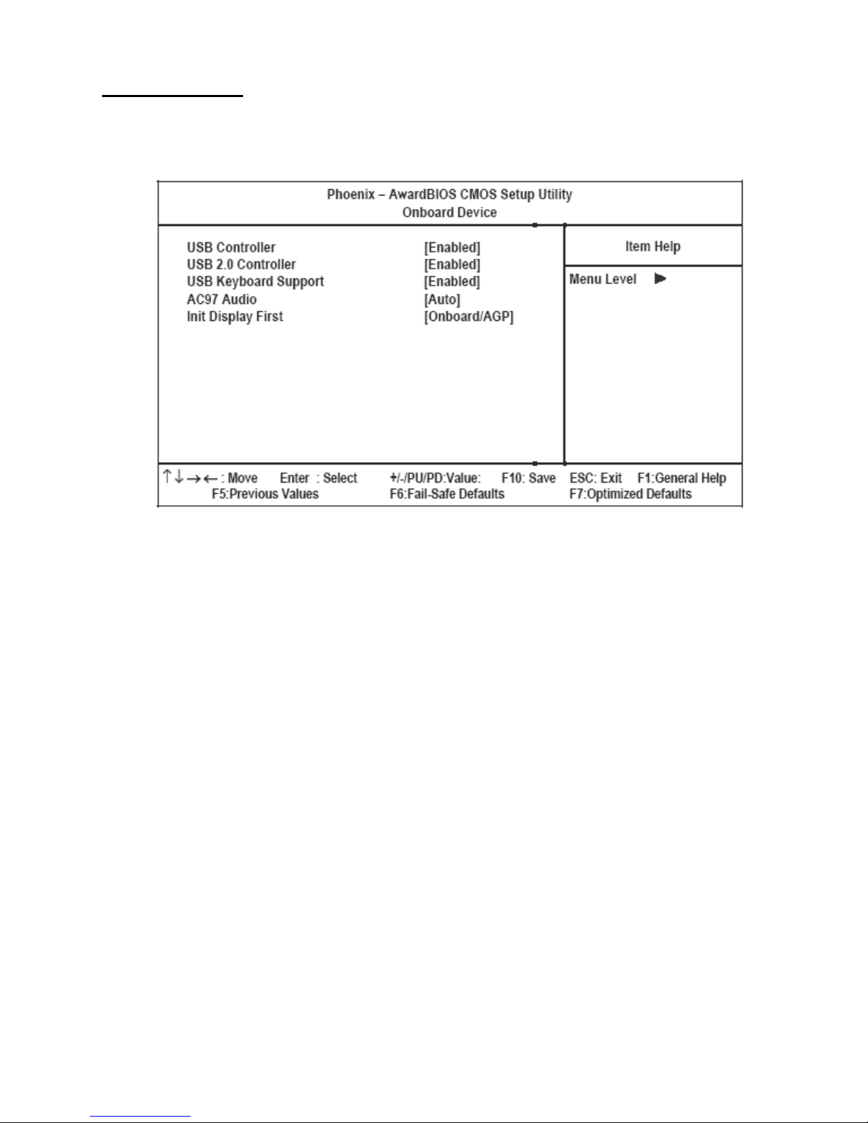
Onboard Device
Use this item to enable or disable the USB and devices that are integrated on the mainboard. Select the item and press
<Enter> to open the following menu:
Figure 3.8 Onboard Device menu
USB Controller
Set this item to Enabled to use USB 1.1 devices. The default setting is Enabled.
USB 2.0 Controller
Set this item to Enabled to use USB 2.0. When set to Disabled, USB 1.1 devices can still be used. The default setting
is Enabled.
USB Keyboard Support
Enable this item if you plan to use a keyboard connected through the USB port in a legacy operating system (such as
DOS) that does not support Plug and Play. This field can only be configured if the “USB Controller” field is enabled.
The default setting is Disabled.
AC97 AUDIO
Enables and disables the onboard audio chip. Disable this item if you are going to install a PCI audio add-in card. The
default setting is Auto.
Init Display First
Use this item to specify whether your graphics adapter is installed in the PCI slot or is integrated on the mainboard.
The default setting is Onboard/AGP.
30 Chapter 3 BIOS Setup Utility
Page 39
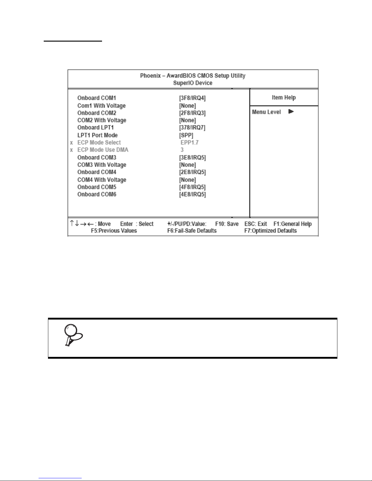
SuperIO Device
Use this item to change settings for I/O devices. Select the item and press <Enter> to open the following menu:
Figure 3.9 Super IO Device menu
Onboard COM1
This option is used to assign the I/O address and IRQ for the onboard COM port 1. The default setting is 3F8/IRQ4.
COM1/2/3/4 With Voltage
COM ports can be set to supply both data and power to the peripherals that connect to them. Check if the device you
connect needs power from the COM port or if it has its own power supply. The factory setting for the COM ports is
None.
The voltage for the COM ports is set at None at the factory. However, for example
to provide power to an installed customer display, this setting must be set at 12V
for the corresponding COM port. For a 5V device such as a barcode scanner, the
IMPORTANT
Onboard COM2
setting should be 5V.
This option is used to assign the I/O address and IRQ for the onboard COM port 2. The default setting is 2F8/IRQ3.
LPT1 Port Mode
Enables you to set the data transfer protocol for the parallel port. There are five options: SPP (Standard Parallel Port),
EPP (Enhanced Parallel Port), ECP (Extended Capabilities Port), ECP+EPP, and PntMode. The default setting is SPP.
SPP allows data output only. Extended Capabilities Port (ECP) and Enhanced Parallel Port (EPP) are bi-directional
modes, allowing both data input and output. ECP and EPP modes are only supported with EPP- and ECP-aware
peripherals. PntMode allows the parallel port to operate in bipoloar mode.
Integrated Peripherals 31
Page 40
ECP Mode Select
Sets the ECP mode version. The default setting is EPP1.7.
ECP Mode Use DMA
When the onboard parallel port is set to ECP mode, the parallel port can use DMA 3 or DMA 1. The default setting is 3.
Onboard COM3
This option is used to assign the I/O address and IRQ for the onboard COM port 3. The default setting is 3E8/IRQ5.
Onboard COM4
This option is used to assign the I/O address and IRQ for the onboard COM port 4. The default setting is 2E8/IRQ5.
Onboard COM5
This option is used to assign the I/O address and IRQ for the onboard COM port 5. The default setting is 4F8/IRQ5.
Onboard COM6
This option is used to assign the I/O address and IRQ for the onboard COM port 6. The default setting is 4E8/IRQ5.
To supply power to the customer display, the COM6 voltage is factory set to
DC+12V.
NOTE
Power Management Setup Option
Use this to control system power management. Modern operating systems take care of much of the power management. This mainboard supports ACPI (Advanced Configuration and Power Interface).
Power Management Timeouts
The power-saving modes can be controlled by timeouts. If the system is inactive for a time, the timeouts begin counting. If the inactivity continues so that the timeout period elapses, the system enters a power-saving mode. If any item in
the list of Reload Global Timer Events is Enabled, then any activity on that item will reset the timeout counters to zero.
Wake Up Calls
If the system is suspended, or has been powered down by software, it can be resumed by a wake up call that is generated by incoming traffic to a modem, a LAN card, a PCI card, or a fixed alarm on the system realtime clock,
32 Chapter 3 BIOS Setup Utility
Page 41
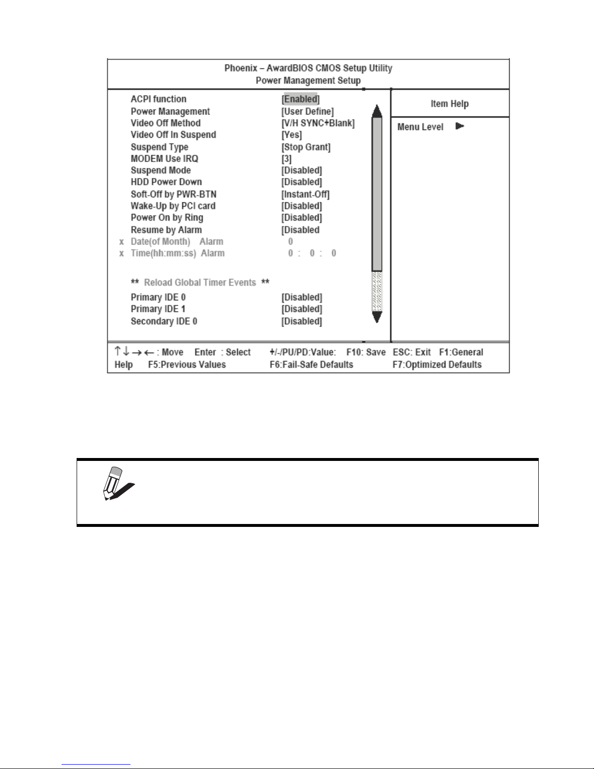
Figure 3.10 Power Management Setup menu
ACPI Function
This mainboard supports ACPI (Advanced Configuration and Power management Interface). Use this item to enable
or disable the ACPI feature. The default setting is Enabled.
ACPI is a power management specification that makes hardware status information available to the operating system. ACPI enables a PC to turn its peripherals
on and off for improved power management. It also allows the PC to be turned
NOTE
Power Management
on and off by external devices, so that mouse or keyboard activity wakes up the
PT-8800.
This item acts like a master switch for the power-saving modes and hard disk timeouts. If this item is set to Max Saving, power-saving modes occur after a short timeout. If this item is set to Min Saving, power-saving modes occur after
a longer timeout. If the item is set to User Define, you can insert your own timeouts for the power-saving modes. The
default setting is User Define.
Video Off Method
This item defines how the video is powered down to save power. The default setting is V/H SYNC+Blank.
Video Off In Suspend
This option defines if the video is powered down when the system is put into suspend mode. The default setting is Yes.
Suspend Type
If this item is set to the default Stop Grant, the CPU will go into Idle Mode during power saving mode.
Power Management Setup Option 33
Page 42

MODEM Use IRQ
If you want an incoming call on a modem to automatically resume the system from a power-saving mode, use this item
to specify the interrupt request line (IRQ) that is used by the modem. You might have to connect the fax/modem to the
mainboard Wake On Modem connector for this feature to work. The default setting is 3.
Suspend Mode
The CPU clock will be stopped and the video signal will be suspended if no Power Management events occur for a
specified length of time. Full power function will return when a Power Management event is detected. Options are
from 1 Min to 1 Hour and Disabled. The default setting is Disabled.
HDD Power Down
The IDE hard drive will spin down if it is not accessed within a specified length of time. Options are from 1 Min to 15
Min and Disabled. The default setting is 15 Min.
Soft-Off by PWR-BTN
Under ACPI (Advanced Configuration and Power management Interface) you can create a software power down. In a
software power down, the system can be resumed by Wake Up Alarms. This item lets you install a software power
down that is controlled by the normal power button on your system. If the item is set to Instant-Off, then the power button causes a software power down. If the item is set to Delay 4 Sec. then you have to hold the power button down for
four seconds to cause a software power down. The default setting is Instant-Off.
Wake-Up by PCI card
Use this item to enable PCI activity to wake up the system from a power-saving mode. The default setting is Disabled.
Resume On LAN
Use this item to enable LAN activity to wake up the system from a power-saving mode. The default setting is Disabled.
Power On by Ring
Use this item to enable modem activity to wakeup the system from a power saving mode.
Resume by Alarm
When set to Enabled, the following two fields become available and you can set the date (day of the month), hour,
minute and second to turn on your system. When set to 0 (zero) for the day of the month, the alarm will power on your
system every day at the specified time. The default setting is Disabled.
Date (of Month) Alarm
When set to “0” the system powers on everyday at the time specified in the “Time (hh:mm:ss) Alarm” field. Select a
date from 1 to 31 for the system to power on at the time specified in the “Time (hh:mm:ss) Alarm” field. The default
setting is 0.
Time (hh:mm:ss) Alarm
Set the time for the system to power on as defined in the ‘Date (of Month) Alarm” field. The time set in this field must
be later than the time in the RTC time as shown in the “Standard CMOS Features” on page 21.
** Reload Global Timer Events **
Global Timer (power management) events are I/O events whose occurrence can prevent the system from entering a
power saving mode or can awaken the system from such a mode. In effect, the system remains alert for anything that
occurs to a device that is configured as Enabled, even when the system is in a power-down mode.
Primary/Secondary IDE 0/1
When these items are enabled, the system will restart the power-saving timeout counters when any activity is detected
on any of the drives or devices on the primary or secondary IDE channels.
34 Chapter 3 BIOS Setup Utility
Page 43
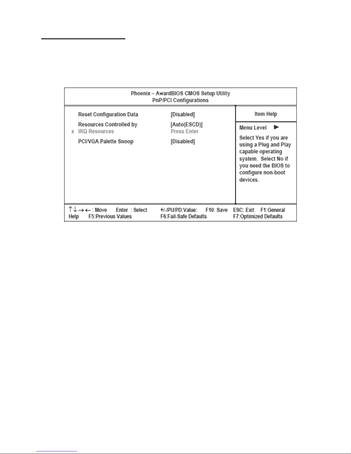
PnP/PCI Configurations
This option configures how PnP (Plug and Play) and PCI expansion cards operate in the system. Both the ISA and PCI
buses on the mainboard use system IRQs (Interrupt ReQuests) and DMAs (Direct Memory Access). You must set up
the IRQ and DMA assignments correctly through PnP/PCI Configurations; otherwise, the mainboard will not work
properly. Selecting “PnP/PCI Configurations” on the main menu displays this menu:
Figure 3.11 PnP/PCI Configurations menu
Reset Configuration Data
If you enable this item and restart the system, any PnP configuration data stored in the BIOS Setup is cleared from
memory. The default setting is Disabled.
Resources Controlled By
You should leave this item at the default Auto (ESCD). Under this setting, the system dynamically allocates resources
to plug and play devices as they are required. If you cannot get a legacy ISA (Industry Standard Architecture) expansion card to work properly, you might be able to solve the problem by changing this item to Manual, and then opening
up the IRQ Resources menu.
IRQ Resources
This menu can only be accessed when the Resources Controlled by menu is set to Manual.
In the IRQ Resources menu, if you change any of the IRQ assignations to Legacy ISA, then that Interrupt Request Line
is reserved for a legacy ISA expansion card. Press <Esc> to close the IRQ Resources menu.
PCI/VGA Palette Snoop
This item is designed to overcome some problems that can be caused by some non-standard VGA cards. This mainboard includes a built-in VGA system that does not require palette snooping so you must leave this item disabled. The
default setting is Disabled.
Press <Esc> to return to the main menu.
Power Management Setup Option 35
Page 44
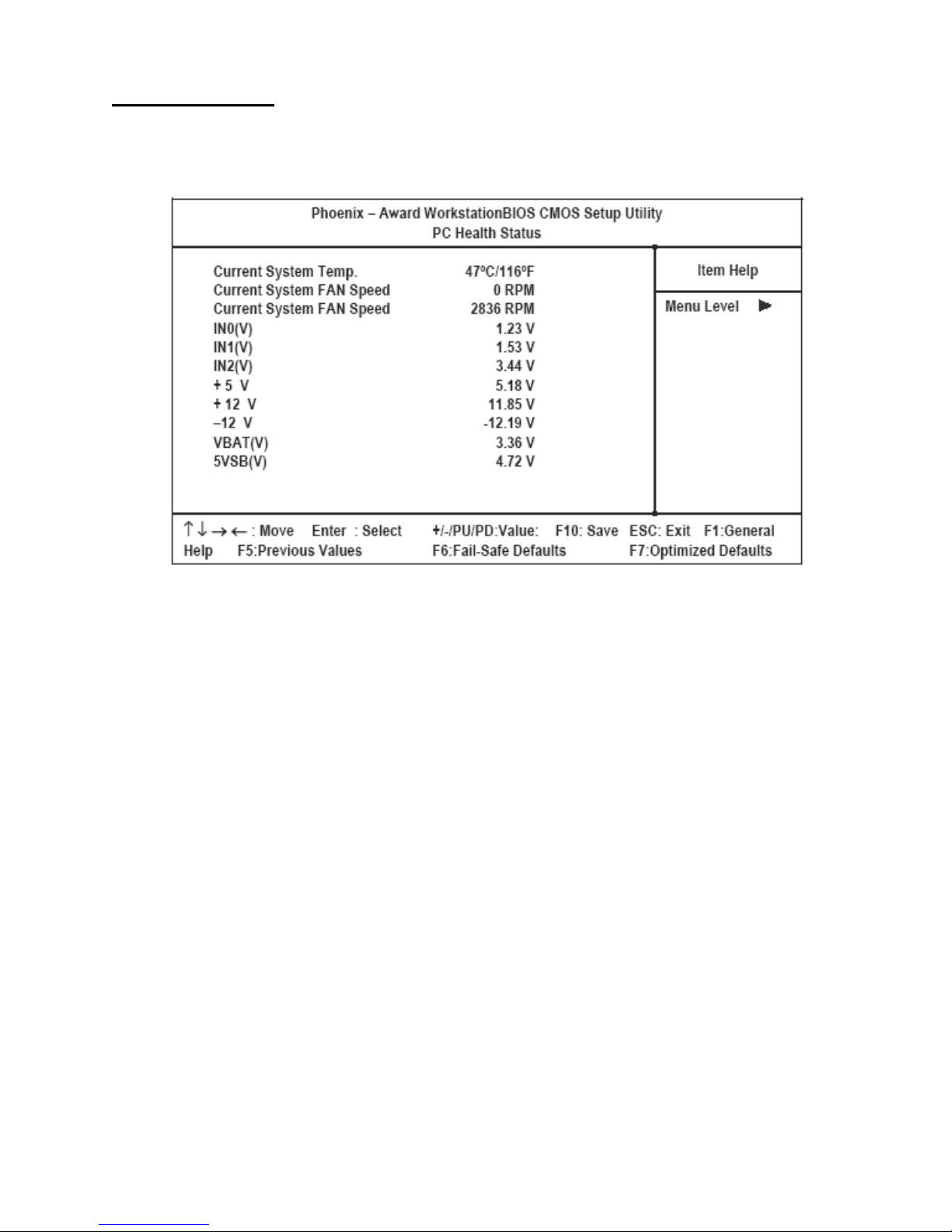
PC Health Status
On mainboards that support hardware monitoring, this item lets you monitor the parameters for critical voltages, critical temperatures, and fan speeds. You cannot make any changes to these fields. They are display only.
Figure 3.12 PC Health Status menu
Press <Esc> to return to the main menu.
36 Chapter 3 BIOS Setup Utility
Page 45
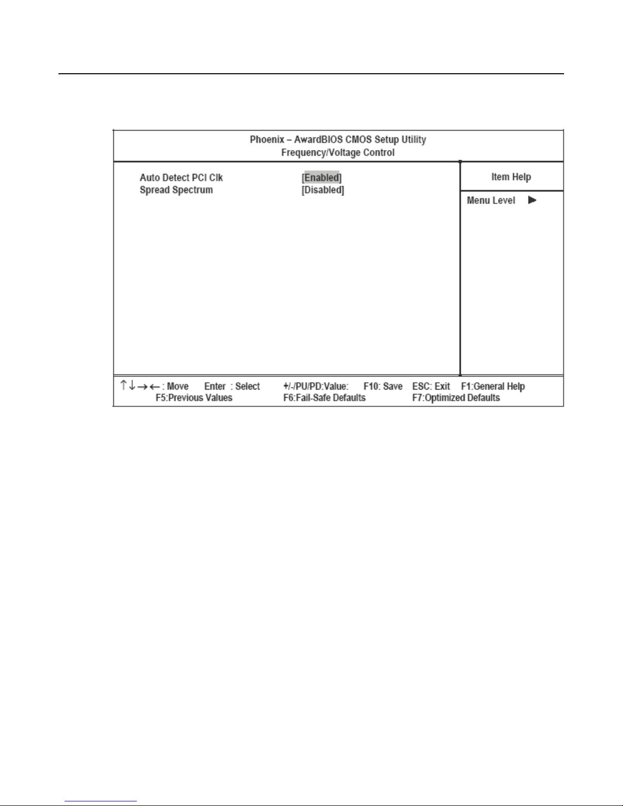
Frequency/Voltage Control Option
This item enables you to set the clock speed and system bus for your system. The clock speed and system bus are
determined by the kind of processor you have installed in your system.
Figure 3.13 Frequency/Voltage Control
Auto Detect PCI Clk
When enabled, BIOS disables the clock signal of unpopulated PCI slots, reducing power consumption. The default setting is Enabled.
Spread Spectrum
Enable this item to significantly reduce the EMI (Electro-Magnetic Interference) generated by the system. The default
setting is +/- 0.45%.
Press <Esc> to return to the main menu.
Frequency/Voltage Control Option 37
Page 46
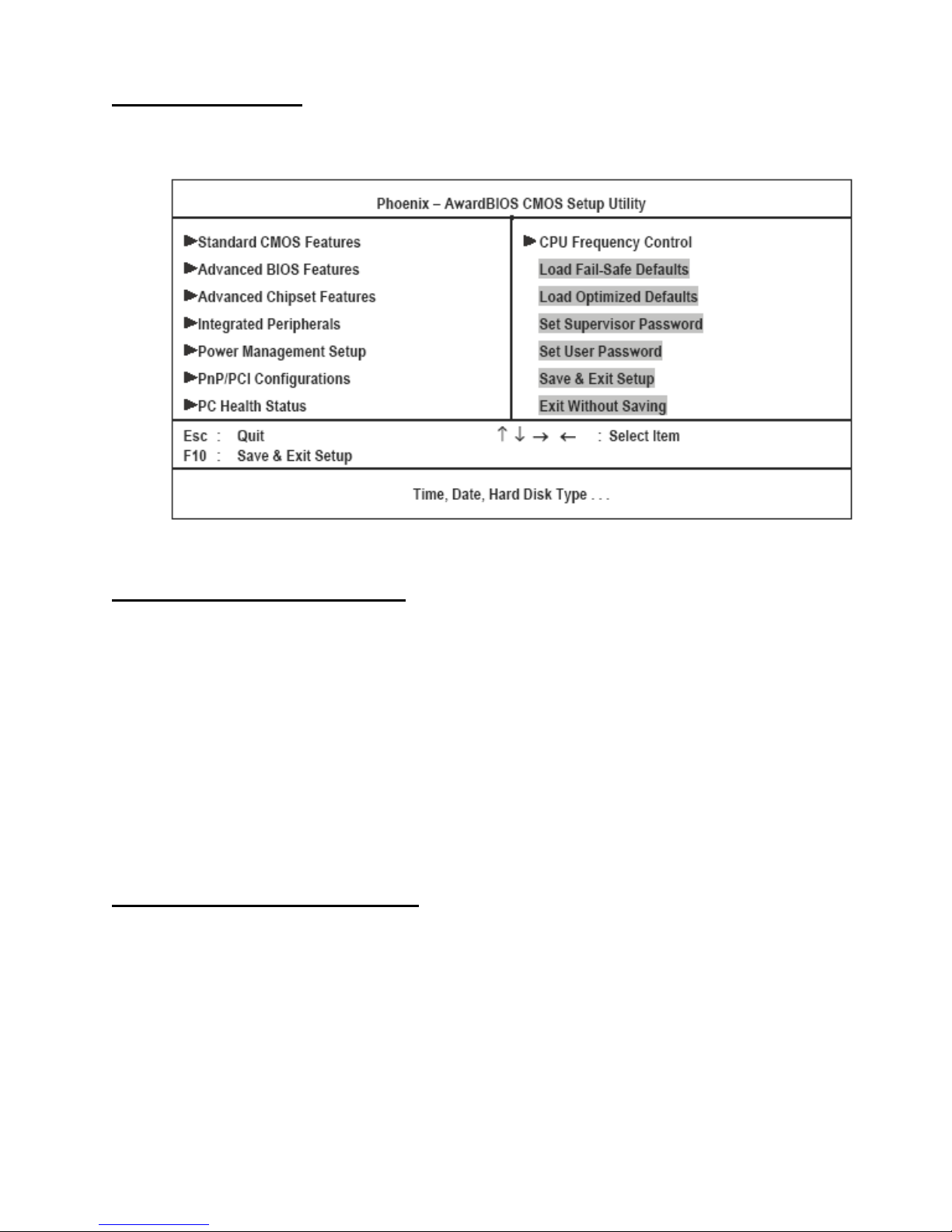
Other BIOS Options
This section covers the other options that are available from the main menu:
Load Fail-Safe Defaults Option
This option opens a dialog box that lets you load fail-safe defaults for all appropriate items in the Setup Utility.
Follow these instructions:
1. From the main menu, scroll to Load Fail-Safe Defaults.
2. Press <Enter> to open the Load Setup Fail-Safe Defaults menu.
3. Press <Y>.
4. Press <Enter> to load the defaults.
The fail-safe defaults place no great demands on the system and are generally stable. If your system is not functioning
correctly, try loading the fail-safe defaults as a first step in getting your system working properly again. If you only
want to load fail-safe defaults for a specific option, select and display that option, and then press <F6>.
Load Optimized Defaults Option
This option opens a dialog box that lets you load optimized defaults for all appropriate items in the Setup Utility.
Follow these instructions:
1. From the main menu, scroll to Load Optimized Defaults.
2. Press <Enter> to open the Load Optimized Defaults menu.
3. Press <Y>.
4. Press <Enter> to load the defaults.
The optimized defaults place demands on the system that may be greater than the performance level of the components, such as the CPU and the memory. You can cause fatal errors or instability if you load the optimized defaults
38 Chapter 3 BIOS Setup Utility
Page 47
when your hardware does not support them. If you only want to load Setup defaults for a specific option, select and
display that option, and then press <F7>.
Set Supervisor and User Passwords Options
These items can be used to install a password. A Supervisor password takes precedence over a User password, and the
Supervisor can limit the activities of a User. To install a password, follow these steps:
1. Highlight the item Set Supervisor/User Password on the main menu and press <Enter>.
2. The password dialog box appears.
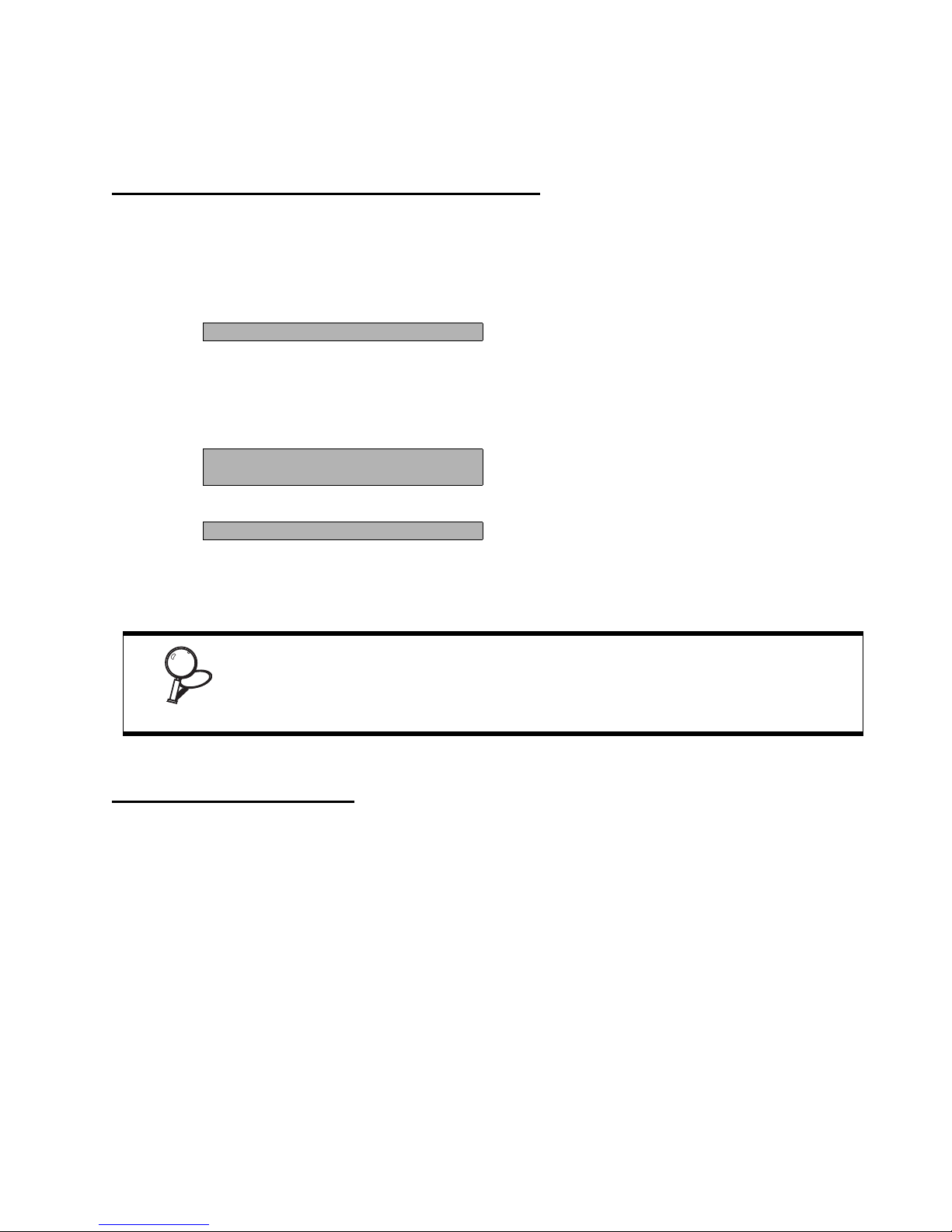
Enter Password:
3. If you are installing a new password, type in the password. You cannot use more than eight characters
or numbers. The Set Supervisor/User Password item differentiates between upper and lower case
characters. Press <Enter> after you have typed in the password. If you are deleting a password that is
already installed press <Enter> when the password dialog box appears. You see a message that
indicates that the password has been disabled.
PASSWORD DISABLED !!!
Press any key to continue . . .
4. Press any key. You are prompted to confirm the password.
Confirm Password:
5. Type the password again and press <Enter>, or press <Enter> if you are deleting a password that is
already installed.
Write the passwords down and keep them in a safe place.
If you do not save changes when you exit BIOS, changes to the passwords will be saved
anyway.
IMPORTANT
Save & Exit Setup Option
Highlight this item and press <Enter> to save the changes that you have made in the Setup Utility and exit the Setup
Utility. When the Save and Exit dialog box appears, press <Y> to save and exit, or press <N> to return to the main
menu.
Frequency/Voltage Control Option 39
Page 48
Exit Without Saving
Highlight this item and press <Enter> to discard any changes that you have made in the Setup Utility and exit the Setup
Utility. When the Exit Without Saving dialog box appears, press <Y> to discard changes and exit, or press <N> to
return to the main menu.
If you have made settings that you do not want to save, use the "Exit Without
Saving" item and press Y to discard any changes you have made.
NOTE
40 Chapter 3 BIOS Setup Utility
Page 49

APPENDIX
This appendix describes locating and solving problems that you may encounter while using the PT-8800.
Troubleshooting
Often after time spent troubleshooting, the problem is traced to something as simple as a loose connection. Check the
following before proceeding to the problem-specific solutions.
Tips for Troubleshooting
In each problem-specific section, try the steps in the order suggested. This may help you to solve the problem more
quickly.
Try to pin point the problem and thus avoid replacing non-defective parts. For example, if you replace batteries and the
problem remains, put the original batteries back and go to the next step.
Keep a record of the steps you take when troubleshooting: The information may be useful when calling for technical
support or for passing on to service personnel.
• Use some other electrical device to confirm that the electrical outlet is working.
• Ensure all connections are securely attached.
The Power-On Self Test
The Power-On Self Test (POST) runs every time you turn on or reset the computer. The POST checks memory, the
mainboard, the display, the keyboard, the disk drives, and other installed options.
If failure is detected in an area other than the mainboard (such as the keyboard or an adapter card), an error message is
displayed on the screen and testing is stopped.
If your system does not successfully complete the POST, but displays a blank screen, have the PT-8800 serviced.
Beep Errors at POST
There are two kinds of beep codes in the BIOS.
• Video error - a single long beep followed by three short beeps indicates a video error, the screen can not be initialized and no information can be displayed.
• DRAM error - a single long beep indicates that a DRAM error has occurred.
41
Page 50
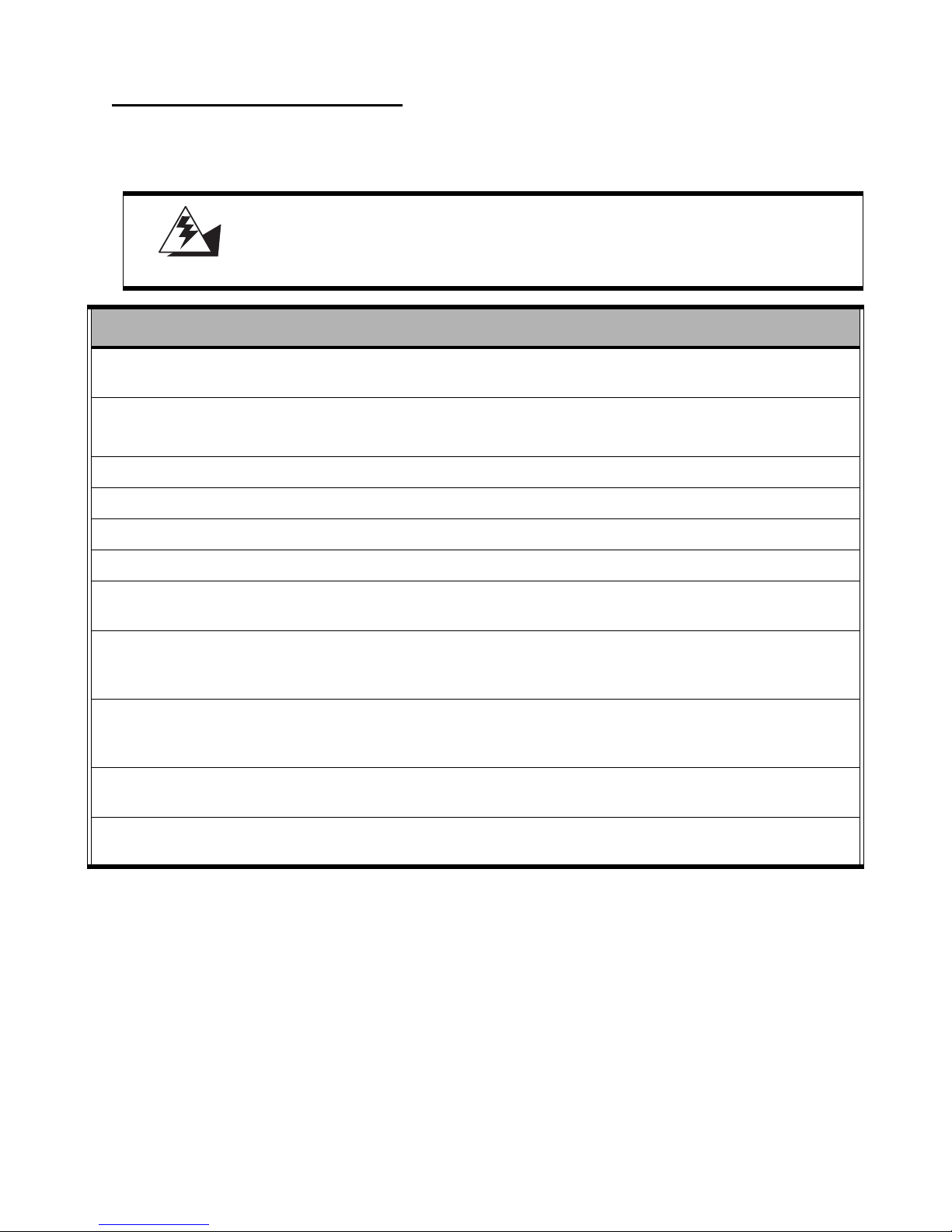
Beep Message Errors at POST
If the BIOS detects an error during the POST, a message is displayed. Refer to the following table for a list of the errors
that display.
The system uses a 3V CR2032 battery (CMOS battery) mounted on the mainboard to keep time. There is a risk of explosion if the wrong battery type is used
when replacing. Dispose of used batteries according to local ordinance regula-
WARNING
ERROR MESSAGE CAUSE SOLUTION
tions.
CMOS BATTERY HAS
FAI LED
CMOS CHECKSUM ERROR The battery may be weak.
HARD DISK(S) FAIL (80) HDD reset failed. Have the PT-8800 serviced.
HARD DISK(S) FAIL (40) HDD controller diagnostics failed. Have the PT-8800 serviced.
HARD DISK(S) FAIL (20) HDD initialization error. Have the PT-8800 serviced.
HARD DISK(S) FAIL (10) Unable to recalibrate fixed disk. Have the PT-8800 serviced.
KEYBOARD IS LOCKED OUT
- UNLOCK THE KEY
KEYBOARD ERROR OR NO
KEYBOARD PRESENT
MANUFACTURING
POST LOOP
BIOS ROM CHECKSUM
ERROR - SYSTEM HALTED
The CMOS battery is depleted. Replace the battery.
Replace the battery.
The CMOS may be corrupt.
The keyboard is locked and the keyboard controller is pulled low.
A keyboard is not detected. Make sure the keyboard is
System keeps rebooting because the
keyboard controller is pulled low for testing purposes.
The ROM address is incorrect. Have the PT-8800 serviced.
Have the PT-8800 serviced.
Have the PT-8800 serviced.
attached correctly and no
key is pressed during boot.
Have the PT-8800 serviced.
MEMORY TEST FAIL The memory card is not correctly
42 Appendix
Have the PT-8800 serviced.
installed or is damaged.
Page 51

General Problems
Refer to the following general problems you may encounter.
PROBLEM SOLUTION
The display screen is dark. Adjust the screen brightness.
Make sure that the PT-8800 is not in suspend mode.
An incorrect date and time are displayed. Correct the date and time using the DOS DATE and TIME
commands or the options in the Setup Utility. (You can also
set the date and time in Windows by double clicking the
clock on the task bar or in the control panel.) If the date and
time become incorrect after a short time, the CMOS battery
may be depleted. Replace the battery.
The following message appears at boot up:
“Invalid system disk,
Replace the disk, and then press any key”
You hear irregular beeps during operation of
the computer and the system halts.
An unidentified message is displayed. Reboot the computer and run the BIOS Setup Utility. Con-
You cannot operate the printer. Check the printer cable connection.
You cannot use a mouse or keyboard. Check the cable connection.
The screen is blank and you don't hear any
beeps.
Ensure that an operating system is installed.
Check the boot sequence in the BIOS setup utility.
Have the PT-8800 serviced.
firm the Setup Utility parameters. If the same message is
displayed after booting up again, have the PT-8800 serviced.
Ensure that the printer power switch is turned on.
Confirm that the printer is on-line.
Check the mouse or keyboard with another computer to see
if it works. If the same problem occurs, replace the mouse
or keyboard.
Check that the AC adapter is connected to the PT-8800 and
the power cord is plugged into a working electrical outlet.
The screen is blank and you hear a continuous beep, or two or more beeps.
Only the cursor appears. Reinstall the operating system, and power on the PT-8800.
Audio problems Ensure the audio cable is not defective.
Check that the power is on. (Press the power switch again
for confirmation.)
Have the PT-8800 serviced.
The mute is off.
Troubleshooting 43
Page 52
Having the PT-8800 Serviced
If you are unable to solve the problem, you should have the projector serviced. Pack the projector in the original carton. (See “Unpacking the PT-8800” on page 1.) Include a description of the problem and a checklist of the steps you
took when trying to fix the problem. The information may be useful to the service personnel. Return the projector to
the place you purchased it.
Specifications
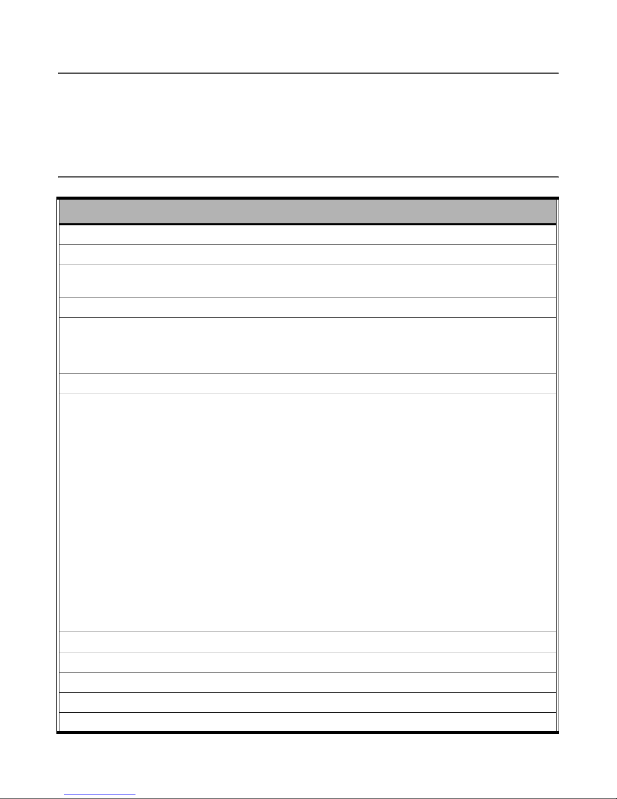
ITEM DESCRIPTION
Processor Socket 478, Intel Pentium 4 – up to 2.8 GHz / Celeron 2.0~2.6 GHz
System bus FSB speed 400/533 MHz
Memory 2 x 184-pin DDR DIMM, support 266/333 MHz DDR SDRAM
(expandable to 2 GB)
Chipset Intel 852 GME integrated high performance 2D/3D graphics
BIOS Award Plug and Play BIOS
Supports APM and ACPI
Jumper-free setting on COM port and cash drawer port voltage selection
LCD panel 15-inch TFT, high brightness LCD
I/O support/connectors Six RS232 ports (4 with +5v/+12vdc power; BIOS selection, jumper free)
Two serial pin-headers on board (1 for touch; 1 for customer display)
One RJ45 with LEDs Ethernet connector, 10/100M/1GHz BASE-T
One PS/2 keyboard port
One PS/2 mouse port
One parallel port
One type II CF card, IDE interface
One DB15 VGA port support dual view / dual contents display
One Cash Drawer port (+24Vdc; BIOS selection, jumper free); support 1
address
Six 2.0 USB ports [4 standard, 2 at the front panel, 2 powered USB
(+12vdc & +24vdc) on rear panel]
MIC-in, Line-Out
One PCI slot
Hard drive One 3.5-inch IDE hard drive
Touch panel (spill proof) Spill proof design resistive or capacitive touch screen
LED status indicators LED for power and HDD
Power supply 220W ATX power supply
Mainboard architecture System Board + I/O Board; connected by connector
44 Appendix
Page 53
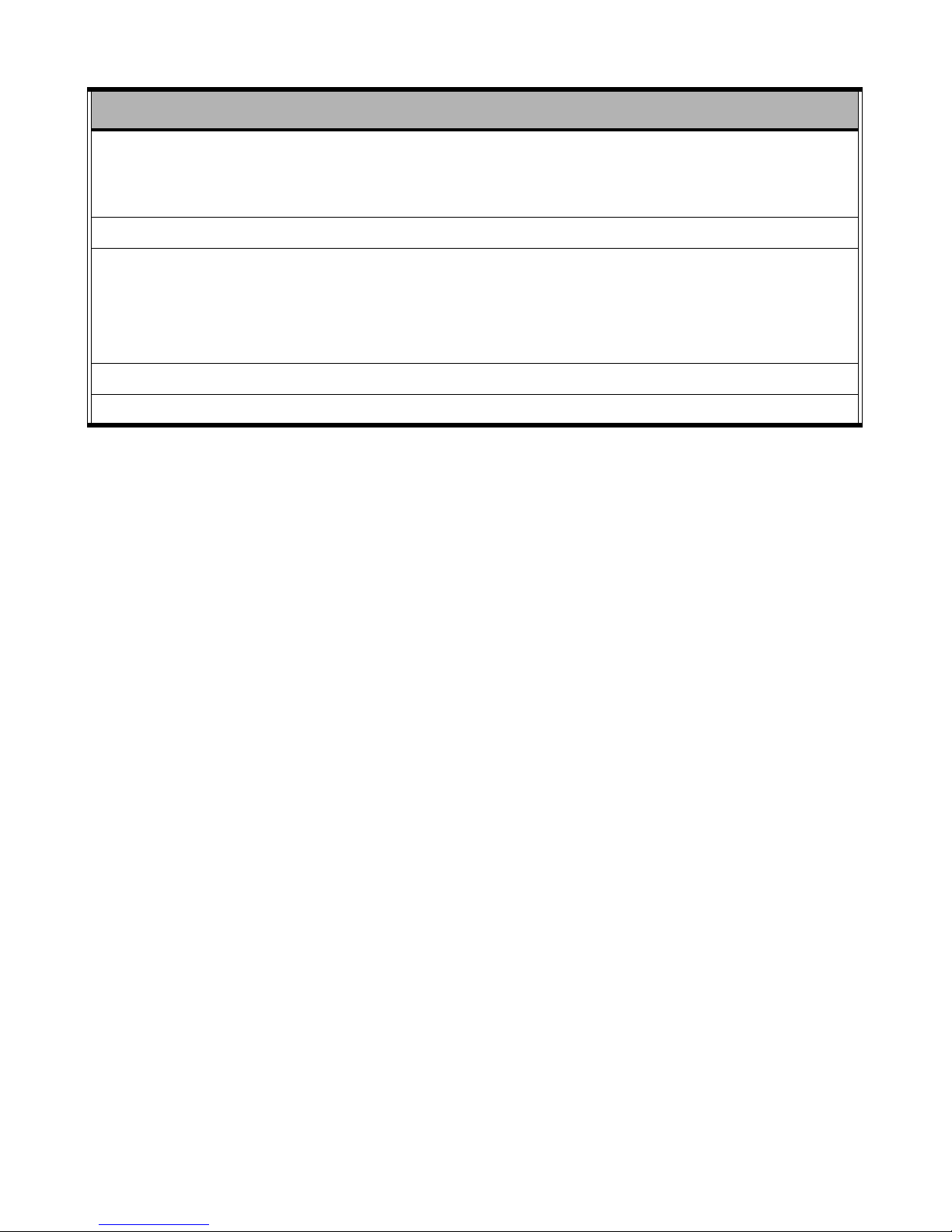
ITEM DESCRIPTION
Environmental Operation temp: 5 ~ 40 degree C
Storage temp:-20 ~ 60 degree C
Humidity: Operation - 20% ~ 85%, Storage: 5% ~ 85%
Power Supply One internal 220w full range ATX power supply.
Options Magnetic card reader (3 tracks)
Internal Smart Card Reader, USB interface
Rear Customer Display, 2 x 20 VFD type
Integrated second screen
Supported operating systems DOS, Windows95/98/2000/ME/XP/XPe, Linux
Safety and EMI CE, FCC, VCCI
Specifications 45
Page 54

46 Appendix
 Loading...