

Page 1

PPTT44000000 PPOOSS SSttaattiioonn
User’s Manual
Page 2

Page 3

P
P
RREEFFAACCE
E
CCooppyyrriigghhtt
This publication, including all photographs, illustrations and software, is
protected under international copyright laws, with all rights reserved.
Neither this manual, nor any of the material contained herein, may be
reproduced without written consent of the author.
Version 1.0
DDiissccllaaiimmeerr
The information in this document is subject to change without notice. The
manufacturer makes no representations or warranties with respect to the
contents hereof and specifically disclaims any implied warranties of
merchantability or fitness for any particular purpose. The manufacturer
reserves the right to revise this publication and to make changes from time
to time in the content hereof without obligation of the manufacturer to notify
any person of such revision or changes.
TTrraaddeemmaarrkk RReeccooggnniittiioonn
Microsoft, MS-DOS and Windows are registered trademarks of Microsoft
Corp.
Other product names used in this manual are the properties of their
respective owners and are ac knowledged.
Page 4

ii
FFeeddeerraall CCoommmmuunniiccaattiioonnss CCoommmmiissssiioonn ((FFCCCC))
This equipment has been tested and found to comply with the limits for a
Class A digital device, pursuant to Part 15 of the FCC Rules. These limits
are designed to provide reasonable protection against harmful interference
in a residential installation. This equipment generates, uses, and can
radiate radio frequency energy and, if not installed and used in accordance
with the instructions, may cause harmful interference to radio
communications. However, there is no guarantee that interference will not
occur in a particular installation. If this equipment does cause harmful
interference to radio or television reception, which can be determined by
turning the equipment off and on, the user is encouraged to try to correct
the interference by one or more of the following measures:
♦ Reorient or relocate the receiving antenna.
♦ Increase the separation between the equipment and the
receiver.
♦ Connect the equipment onto an outlet on a circuit different
from that to which the receiver is connected.
♦ Consult the dealer or an experienced radio/TV technician for
help.
Shielded interconnect cables and a shielded AC power cable must be
employed with this equipment to ensure compliance with the pertinent RF
emission limits governing this device. Changes or modifications not
expressly approved by the system's manufacturer could void the user's
authority to operate the equipment.
DDeeccllaarraattiioonn ooff CCoonnffoorrmmiittyy
This device complies with part 15 of the FCC rules. Operation is subject to
the following conditions:
♦ This device may not cause harmful interference, and
♦ This device must accept any interference received, including
interference that may cause undesired operation.
Page 5

iii
AAbboouutt tthhiiss MMaannuuaall
The manual consists of the following sections:
♦ Chapter 1: Introducing the POS Station: provides general
information on the POS Station, a packing list, and illustrations
of the POS Station components.
♦ Chapter 2: Setting Up the System: provides information on
attaching peripheral and optional devices.
♦ Chapter 3: Installing Drivers and Software: gives you
detailed information on installing device drivers and software
for Windows operating systems.
♦ Chapter 4: Using the Touchscreen: provides instructions for
using the Touchscreen feature.
♦ Chapter 5: Using BIOS: gives instructions on using the BIOS.
♦ Appendix A: Specifications: provides detailed specifications
for the POS Station.
♦ Appendix B: Troubleshooting: gives troubleshooting
procedures for the POS Station.
♦ Appendix C: Jumper Settings: provides jumper settings.
Page 6

iv
S
S
AAFFEETTYY
I
I
NNFFOORRMMAATTIIOON
N
Before installing and using the PT-4000 POS Station, take note of the
following precautions:
♦ Read all instructions carefully.
♦ Do not place the unit on an unstable surface, cart, or stand.
♦ Do not block the slots and opening on the unit, which are
provided for ventilation.
♦ Only use the power source indicated on the marking label. If
you are not sure, contact your dealer or the Power Company.
♦ The unit uses a three-wire ground cable, which is equipped
with a third pin to ground the unit and prevent electric shock.
Do not defeat the purpose of this pin. If your outlet does not
support this kind of plug, contact your electrician to replace
your obsolete outlet.
♦ Do not place anything on the power cord. Place the power cord
where it will not be in the way of foot traffic.
♦ Follow all warnings and cautions in this manual and on the unit
case.
♦ Do not push objects in the ventilation slots as they may touch
high voltage components and result in shock and damage to
the components.
♦ When replacing parts, ensure that your service technician uses
parts specified by the manufacturer.
♦ When service or repairs have been done, ensure that the
service technician performs routine safety checks to verify that
the system is operating correctly.
♦ Avoid using the system near water, in direct sunlight, or near a
heating device.
♦ Cover the unit when not in use.
Page 7

v
T
T
AABBLLEE OOFF
C
C
OONNTTEENNTTS
S
PT4000 POS STATION 1
CHAPTER 1: INTRODUCING THE POS STATION 1
A Tour of the POS Station...............................................................1
Configuration Options..............................................................................................2
Package Contents......................................................................................................3
Options.........................................................................................................................4
Front View..................................................................................................................5
Rear View....................................................................................................................6
The IR Communication Module (Optional)........................................................7
The IR Keyboard (optional).....................................................................................8
Rotating the LCD Panel...................................................................9
Wall Mounting Option...................................................................10
CHAPTER 2: SETTING UP THE SYSTEM 11
Precautions ....................................................................................11
Before You Begin...........................................................................12
PT-4000 POS Station Overview.....................................................13
Main LCD Panel/CPU Unit..................................................................................13
Pedestal Unit.............................................................................................................13
Power Supply Unit...................................................................................................13
Attaching Optional Devices............................................................14
Removing the Rear Cover......................................................................................14
Removing the Front Cover....................................................................................15
Attaching the CD-ROM..........................................................................................17
Attaching the Floppy Disk Drive..........................................................................20
Replacing the Hard Disk Drive.............................................................................24
Attaching the Magnetic Strip Reader..................................................................26
Attaching the Rear Customer Display.................................................................30
Attaching the Customer Pole Display.................................................................33
Connecting I/O devices...................................................................35
Connecting a PS/2 Keyboard and Mouse...........................................................36
Connecting a Printer...............................................................................................36
Connecting a VGA Monitor..................................................................................37
Connecting Serial Devices.....................................................................................37
Connecting a Cash Drawer ...................................................................................38
Page 8

vi
Connecting USB Devices.......................................................................................38
Connecting Speakers..............................................................................................39
Connecting to a LAN..............................................................................................39
Starting the System........................................................................40
Checking the Power Supply...................................................................................40
Turning the System On..........................................................................................41
Adjusting the Display Brightness.........................................................................42
CHAPTER 3: INSTALLING DRIVERS AND SOFTWARE 43
PT4000 Driver Installation.............................................................43
Autoinstallation........................................................................................................43
Manual Installation................................................................................................45
Other Drivers and Utilities.....................................................................................49
CHAPTER 4: USING THE TOUCHSCREEN 53
About the Touchscreen..................................................................53
Touchscreen Basics.................................................................................................53
CHAPTER 5: USING BIOS 57
About the Setup Utility..................................................................57
The Standard Configuration.................................................................................58
Entering the Setup Utility......................................................................................59
The PT-4000 POS Station BIOS.....................................................61
Standard CMOS Setup ...........................................................................................61
BIOS Features Setup ..............................................................................................64
Chipset Features Setup...........................................................................................68
Power Management Setup Option.......................................................................70
PNP/PCI Configuration Option...........................................................................74
Integrated Peripherals Option..............................................................................76
Other BIOS Options ......................................................................80
IDE HDD Auto Detection Option........................................................................80
Load BIOS Defaults Option..................................................................................81
Load Setup Defaults Option..................................................................................81
Set Supervisor and User Passwords Options.....................................................82
Save & Exit Setup Option......................................................................................83
Exit Without Saving................................................................................................83
APPENDIX A: SPECIFICATIONS 84
PT-4000 LCD POS Terminal Specifications ...................................84
APPENDIX B: TROUBLESHOOTING 86
Page 9

vii
Locating a Problem........................................................................86
Checking Cables and Connections .................................................87
The Power-On Self Test.................................................................87
General Hardware Problems .........................................................88
Contacting Your Dealer.................................................................89
APPENDIX C: JUMPER SETTINGS 90
PT-4000 POS Station PCB Jumper Settings...................................90
Power PCB Jumpers...............................................................................................91
Base PCB Jumpers..................................................................................................92
MSR PCB Jumpers .................................................................................................93
Page 10

viii
T
T
AABBLLEE OOFF
F
F
IIGGUURREES
S
FIGURE 1 – SAMPLE CONFIGURATION................................................................................2
FIGURE 2 – PT-4000 POS STATION FRONT VIEW..............................................................5
FIGURE 3 – PT-4000 POS STATION REAR VIEW................................................................6
FIGURE 4 – INFRARED MODULE SETUP...............................................................................8
FIGURE 5 – ROTATING THE LCD PANEL.............................................................................9
FIGURE 6 – PT-4000 POS STATION SECURED TO A WALL..............................................10
FIGURE 7 – CONNECTING PERIPHERAL DEVICES.............................................................35
FIGURE 8 – CONNECTING A PS/2 MOUSE OR KEYBOARD...............................................36
FIGURE 9 – CONNECTING A PRINTER................................................................................36
FIGURE 10 – CONNECTING AN EXTERNAL MONITOR......................................................37
FIGURE 11 – CONNECTING A SERIAL DEVICE...................................................................37
FIGURE 12 – CONNECTING A CASH DRAWER...................................................................38
FIGURE 13 – CONNECTING USB DEVICES.......................................................................38
FIGURE 14 – CONNECTING STEREO SPEAKERS................................................................39
FIGURE 15 – CONNECTING TO THE LAN..........................................................................39
FIGURE 16 – TURNING THE SYSTEM ON...........................................................................41
FIGURE 17 – ADJUSTING DISPLAY BRIGHTNESS ..............................................................42
FIGURE 18– PT-4000 POS STATION BIOS MAIN SCREEN..............................................59
FIGURE 19 – LOCATION OF PCB BOARDS........................................................................90
FIGURE 20 – POWER PCB ..................................................................................................91
FIGURE 21 – BASE PCB......................................................................................................92
FIGURE 22 – MSR PCB ......................................................................................................93
Page 11

CChhaapptteerr 11:: IInnttrroodduucciinngg tthhee PPOOSS SSttaattiioonn
AA TToouurr ooff tthhee PPOOSS SSttaattiioonn
The PT-4000 provides you with a fast and accurate point-of-sales (POS)
solution for use in supermarkets, information kiosks, restaurants, and
other hospitality service areas. The 12.1 or 13.3 -inch LCD panel displays
provide a clear color TFT (DSTN optional) interface, giving superior
resolution and monitor capabilities. The PT-4000 also features an
integrated touch screen, enabling users to access the system using their
fingers or a stylus.
The PT-4000 POS Station’s mainboard supports Intel Celeron processors
up to 700 MHz, and Pentium III processors from 500 to 750 MHz and
above. The mainboard accommodates SDRAM memory up to 512 MB.
A 3.5-inch IDE hard disk drive (HDD) provides the core storage of the
unit. An internally mounted 2.5-inch IDE HDD is optional. The storage
features of the station include a DiskOnChip, which is expandable to 288
MB. The DiskOnChip is shared with an optional SSD (Solid State Disk).
The PT-4000 POS Station comes with the following I/O interfaces:
• 4 RS232 ports, 3 external with D9 pin connector with +5 VDC or
+12 VDC (set by jumper)
• 1 parallel port
• 1 Ethernet, 10/100 BASE-T
• 1 PS/2 keyboard port
• 1 PS/2 mouse port
• 1 XVGA (CRT supports up to 1024x768)
• 1 cash drawer port supporting two cash drawers
• 2 USB ports
• Audio out
• Cash drawer power port (24 VDC)
Page 12
2
CCoonnffiigguurraattiioonn OOppttiioonnss
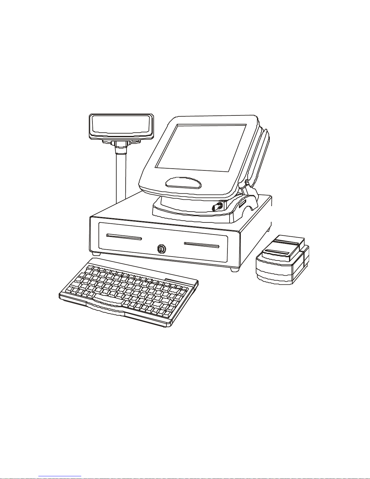
The PT-4000 POS Station has many optional devices that you can connect
to:
Figure 1 – Sample Configuration
Customer pole
display
Cash drawer
Printer
Infrared
keyboard
PT-4000 POS Station
Page 13

3
PPaacckkaaggee CCoonntteennttss
The PT-4000 POS Station comes securely packaged in a sturdy cardboard
shipping carton. Upon receiving your PT-4000 POS Station, open the
carton and carefully remove the contents. If anything is missing or
damaged, please contact your dealer immediately. The shipping carton
should contain the following items:
• One PT-4000 POS Station (including one pedestal with keylock)
• One power supply unit and AC power cord
• One HDD cable
• One FDD cable
• Cable securing straps
• Screws
• Support driver and utility CD-ROM or diskettes
• One front base cover
• One rear base cover
• Two hinge covers
Page 14

4
OOppttiioonnss
• Single, dual, or triple track magnetic card reader
• Barcode card reader
• Pole display for customer
• Rear display for customer
• PCMCIA or fax/modem
• Internal floppy drive or CD-ROM drive
• Internal Smart Card Reader
• RF (Radio Frequency) reader
• CCD (barcode scanner)
• Hard disk drive
• Infrared keyboard
• Supported operating systems:
– DOS
– Windows 2000/ME/98/95/NT
Note! The barcode reader and RF reader connect to MSR PCB JP4
connector (refer to the Appendix C). The smart card connects to a
COM port. A CCD (barcode scanner) can connect to a PS/2 keyboard
or a COM port.
Page 15
5
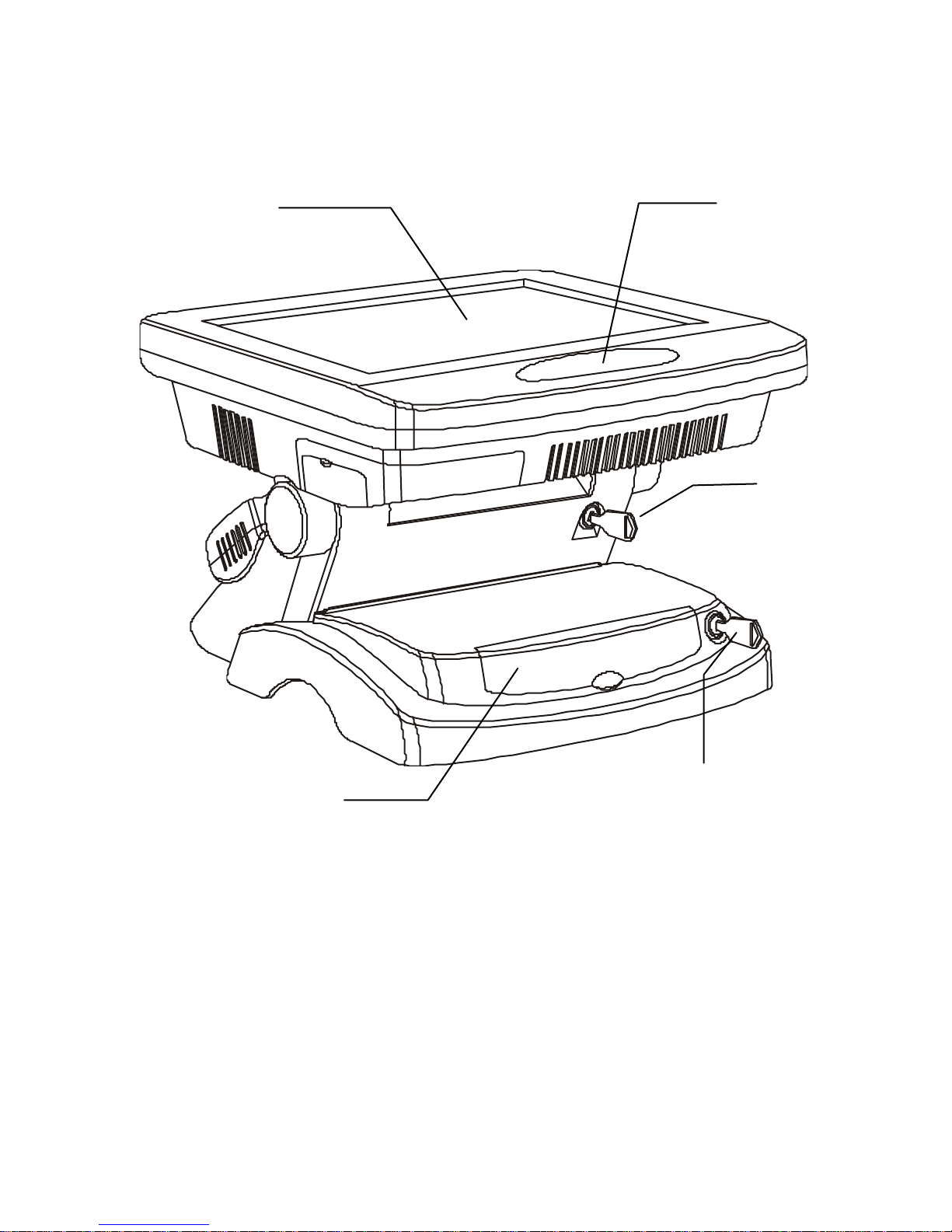
FFrroonntt VViieeww
Figure 2 – PT-4000 POS Station front view
LCD panel
Rear cover
release lock
IR port
CD-ROM or floppy disk
drive (optional)
CD-ROM/FDD cover
release lock
Page 16
6
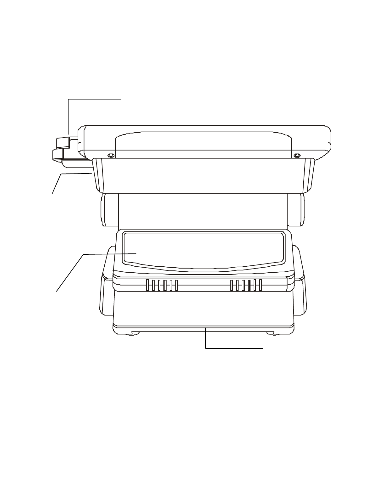
RReeaarr VViieeww
Figure 3 – PT-4000 POS Station rear view
Rear
customer
display
(optional)
Power
switch
I/O ports
(behind panel)
Magnetic card
reader (optional)
Page 17

7
TThhee IIRR CCoommmmuunniiccaattiioonn MMoodduullee ((OOppttiioonnaall))
The PT-4000 POS Station is equipped with an Infrared (IR)
communication module located on the front of the station. If you are
having trouble finding this module, please see Front View on page 5. The
IR module consists of one Light Emitting Diode (LED) and one photo
sensor. The operation of the IR module is similar to the operation of a
television remote control device.
The IR module enables you to perform wireless, serial communication.
Use an SIR-specified application to transmit or receive data via the PT-
4000 POS Station IR module. You can set IR preferences in the Integrated
Peripherals screen in BIOS. Please refer to Chapter 5 for information on
the BIOS Setup program.
Follow the guidelines listed below when using the infrared
communication module to transmit or receive data.
• Ensure that the PT-4000 POS Station IR module is properly
aligned with the other device’s infrared communication module.
The angle between the two infrared communication modules
should not exceed ±15°.
• There should be a clear path between the two Infrared
communication modules; otherwise, the optical signal will be
blocked. Likewise, do not place anything between the two
infrared communication modules during data transmission.
• Make sure the distance between the PT-4000 POS Station IR
module and the other device’s infrared communication module is
not closer than 15 cm and does not exceed seven meters.
• Do not move either the PT-4000 POS Station or the other device
during transmission of data; otherwise, data transmission will be
distorted resulting in loss of data or a system crash.
• An error can occur if IR transmission is conducted in an
environment with high levels of noise. To avoid transmission
errors do not transmit infrared communication signals near
equipment with compressors, such as refrigerators or air
conditioners.
Page 18
8
TThhee IIRR KKeeyybbooaarrdd ((ooppttiioonnaall))
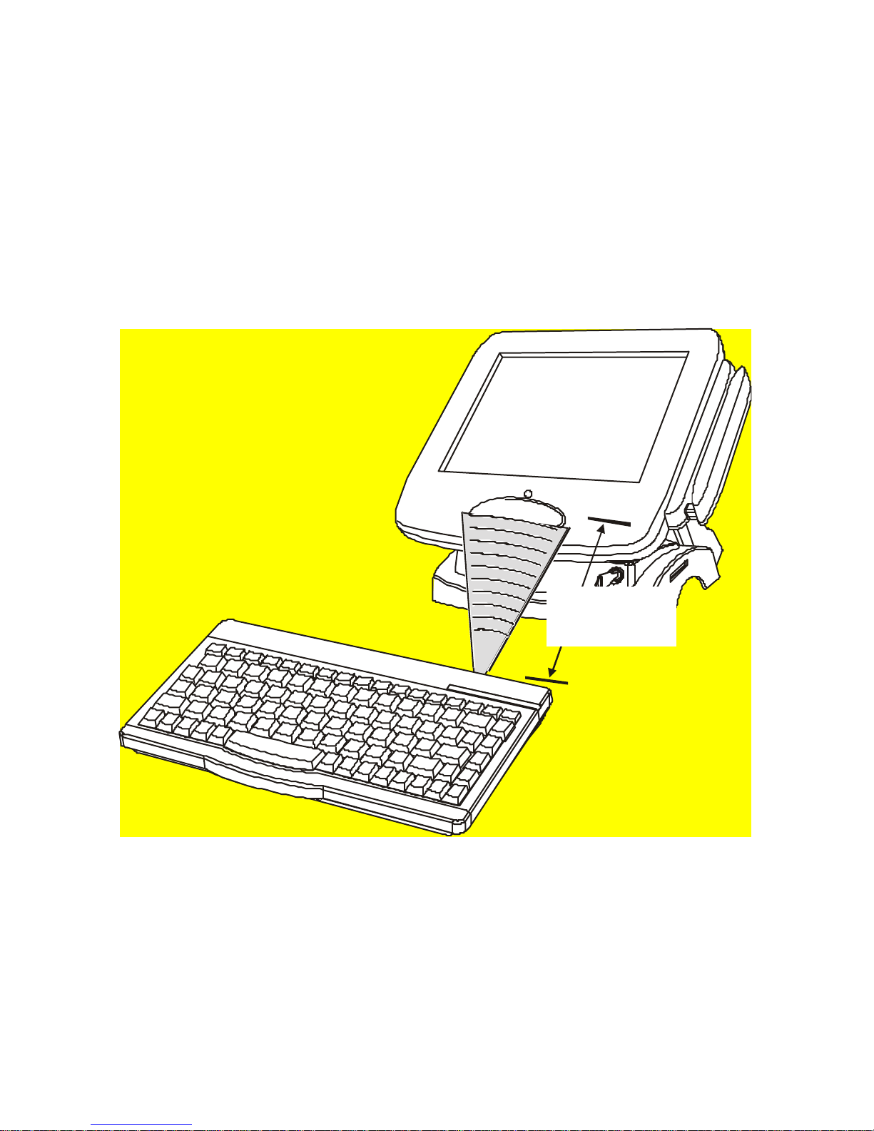
The PT-4000 POS Station has an optional IR keyboard, providing greater
expandability and flexibility for setting up and maintaining the station.
The IR keyboard has integrated firmware, and is automatically installed
in Windows 2000/ME/98/95/NT.
Refer to the following illustration for proper usage of the IR keyboard:
30
15 cm min.
7M max.
Figure 4 – Infrared module setup
Page 19
9
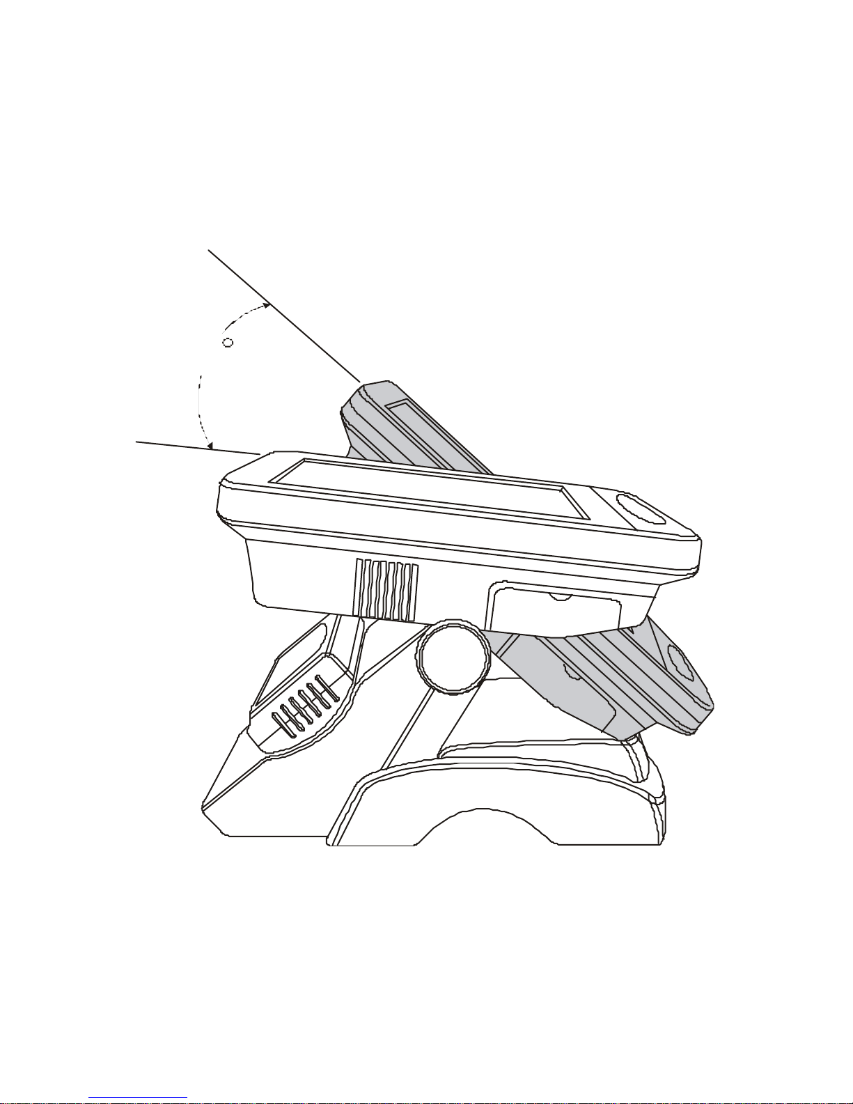
RRoottaattiinngg tthhee LLCCDD PPaanneell
The LCD panel can be rotated to provide convenient access to the CDROM/FDD drive and to enable you to change the HDD drive. The
rotation provides flexible viewing angles for all types of environments:
45
Figure 5 – Rotating the LCD panel
Page 20
10
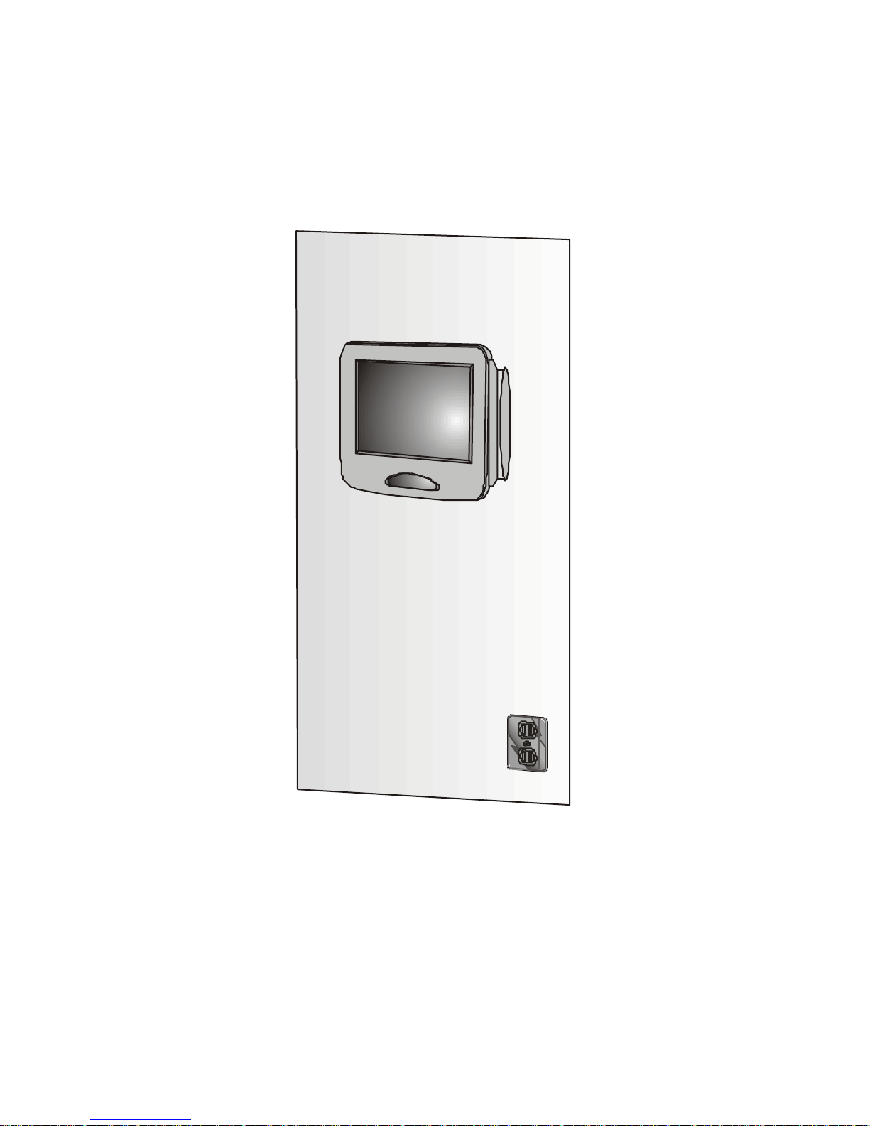
WWaallll MMoouunnttiinngg OOppttiioonn
The PT-4000 POS Station can be mounted on a wall providing greater
versatility in setting up your POS system:
Figure 6 – PT-4000 POS Station secured to a wall
Contact your dealer for details about mounting options.
This concludes Chapter 1. The next chapter covers installation of the
system.
Page 21

CChhaapptteerr 22:: SSeettttiinngg UUpp tthhee SSyysstteemm
PPrreeccaauuttiioonnss
Computer components and electronic circuit boards can be damaged by
discharges of static electricity. Working on computers that are still
connected to a power supply can be extremely dangerous. Follow the
simple guidelines below to avoid damage to your computer or injury to
yourself.
• Always disconnect the unit from the power outlet.
• If available, wear a grounded wrist strap. Alternatively, discharge
any static electricity by touching the bare metal chassis of the unit
case, or the bare metal body of any other grounded appliance.
• Hold electronic circuit boards by the edges only. Do not touch the
components on the board unless it is necessary to do so. Do not
flex or stress the circuit board.
• Leave all components inside the static-proof packaging that they
ship with until they are ready for installation.
• After replacing optional devices, make sure all screws, springs, or
other small parts are in place and are not left loose inside the case.
Metallic parts or metal flakes can cause electrical shorts.
Page 22

12
BBeeffoorree YYoouu BBeeggiinn
Make sure you have a stable, clean working environment. Dust and dirt
can get into computer components and cause a malfunction. Use
containers to keep small components separated. Putting all small
components in a safe container keeps them from becoming lost. Adequate
lighting and proper tools can prevent you from accidentally damaging the
internal components. The procedures that follow require only a few
simple tools, including the following:
• A Philips screwdriver
• A flat-tipped screwdriver
• A set of jewelers screwdrivers
• A grounding strap
• An anti-static pad
Most of the electrical and mechanical connections can be disconnected by
using your fingers. It is recommended that you do not use needle -nosed
pliers to disconnect connectors as these can damage the soft metal or
plastic parts of the connectors.
Page 23

13
PPTT--44000000 PPOOSS SSttaattiioonn OOvveerrvviieeww
The PT-4000 POS Station is configured into three main units. This section
describes these units.
MMaaiinn LLCCDD PPaanneell//CCPPUU UUnniitt
The LCD Panel/CPU unit provides all computer functions. This unit
contains the following components:
• Mainboard
• On/off switch
• Serial and parallel port connections
• Micro PCI connection
• MSR connection
• HDD and power indicators
• Touchscreen
• Cover plate for port connections
PPeeddeessttaall UUnniitt
The pedestal unit provides the structural base of the POS. This unit
consists of the following:
• Metal base for installation of the HDD and optional FDD or CD-
ROM drive
• Hinge connection to main CPU unit
• Front base cover
• Rear base cover
• Customer display panel
• Key-lock interface
PPoowweerr SSuuppppllyy UUnniitt
The power supply unit provides power to the entire system. The power
supply unit consists of:
• Main power input socket chassis
• Output DC voltage
Note! The power supply unit has an automatic power switch for selecting
either 115 or 230 VAC.
Page 24
14
AAttttaacchhiinngg OOppttiioonnaall DDeevviicceess
This section provides information on installing optional devices.
Notes! 1. The arrows in the following procedures show the direction of
movement to remove/replace a device or component, or to turn a
screw or key to release a device.
2. All connectors are keyed to only attach one way.
3. Always use the correct screw size as indicated in the procedures.
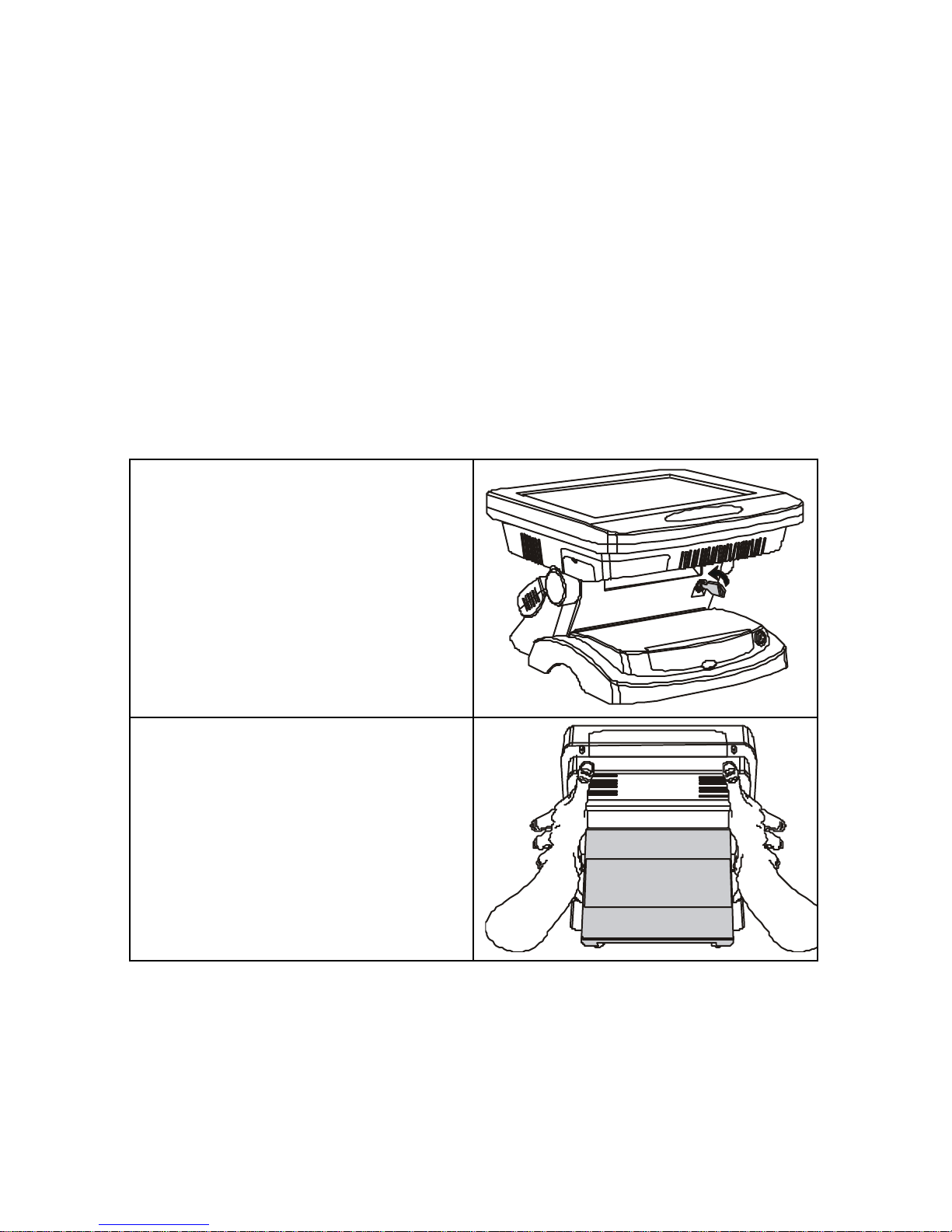
RReemmoovviinngg tthhee RReeaarr CCoovveerr
Follow these instructions:
1. Ensure that the power supply is
disconnected.
2. Turn the key to the left to unlock
the rear cover:
3. Turn the POS around. With
thumbs positioned as shown, grip
the sides of the rear cover and
remove the cover:
Page 25
15
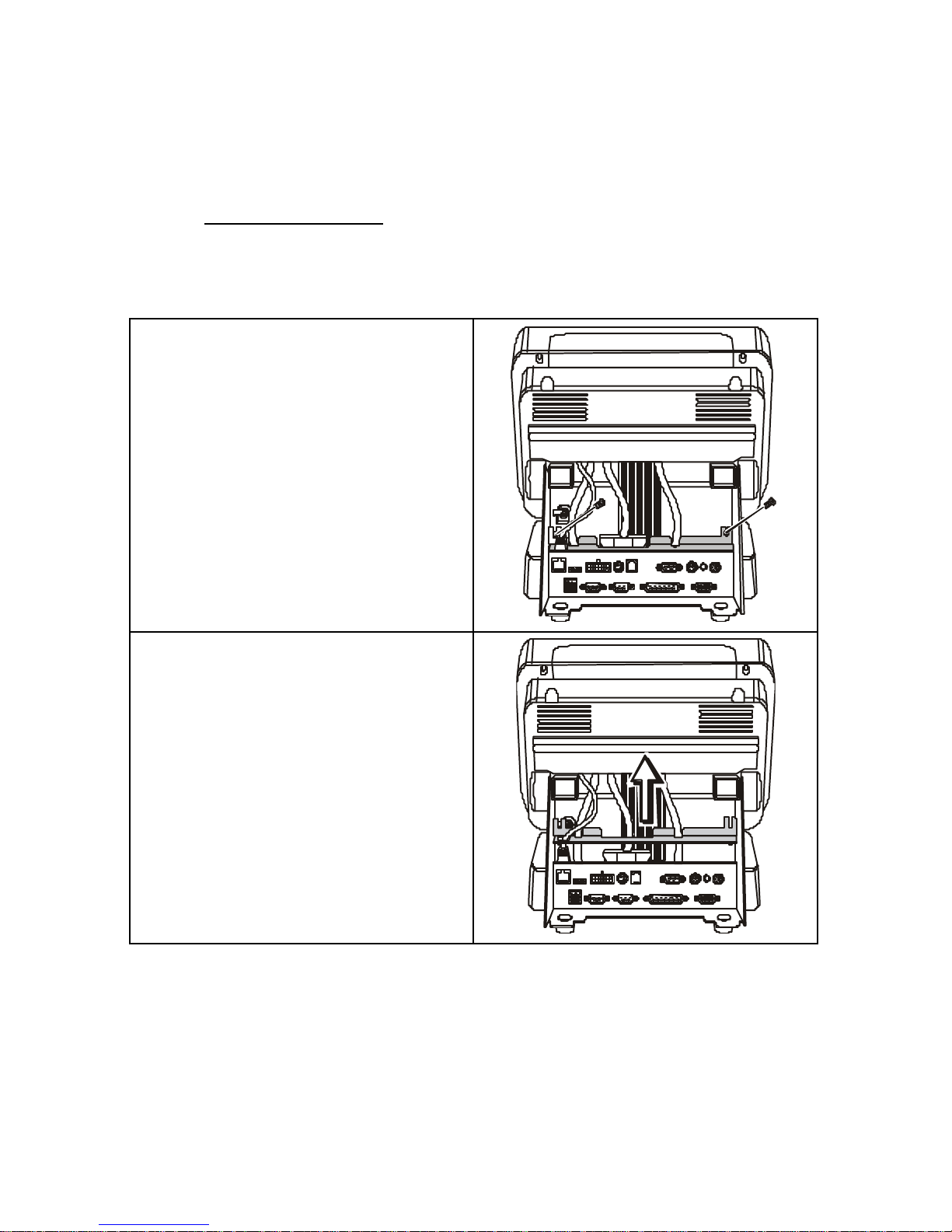
RReemmoovviinngg tthhee FFrroonntt CCoovveerr
Before proceeding
Remove the Rear Cover (see page 14).
Follow these instructions:
1. At the rear of the unit, remove the
two screws from the PCB board
cover:
2. Lift the PCB board cover:
Page 26
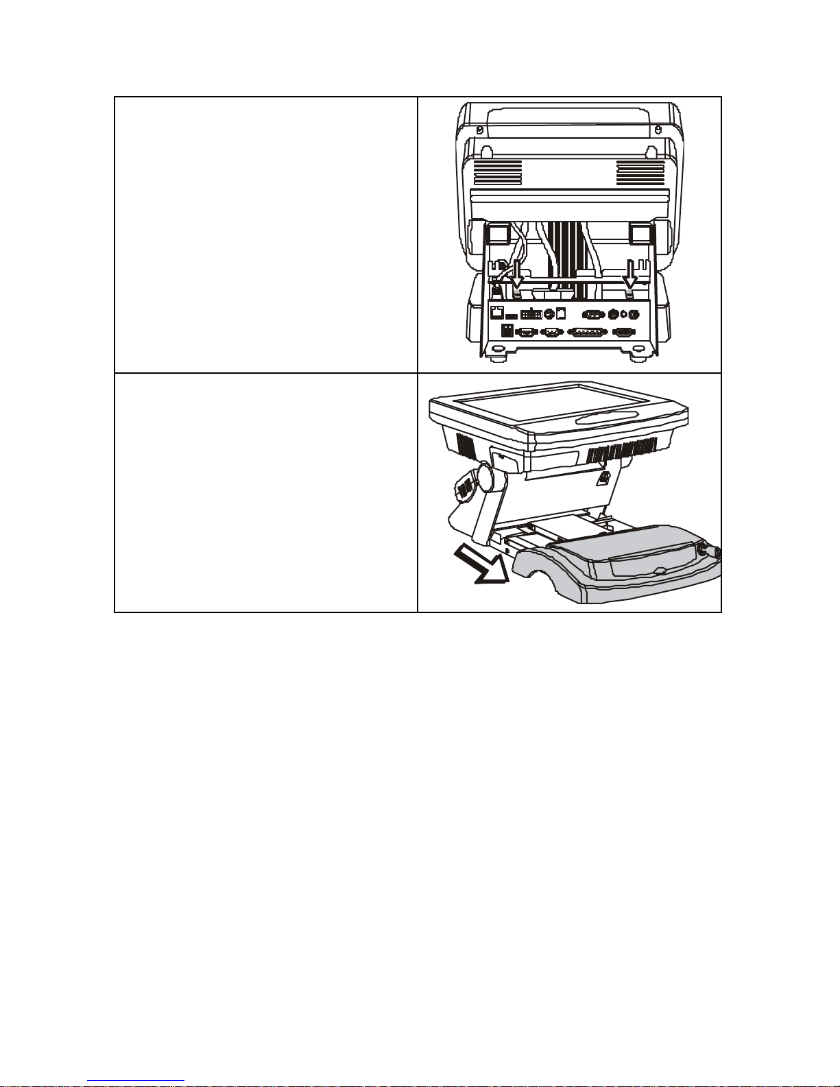
16
3. Press the front cover clips down to
release the front cover:
4. Remove the front cover:
Page 27
17
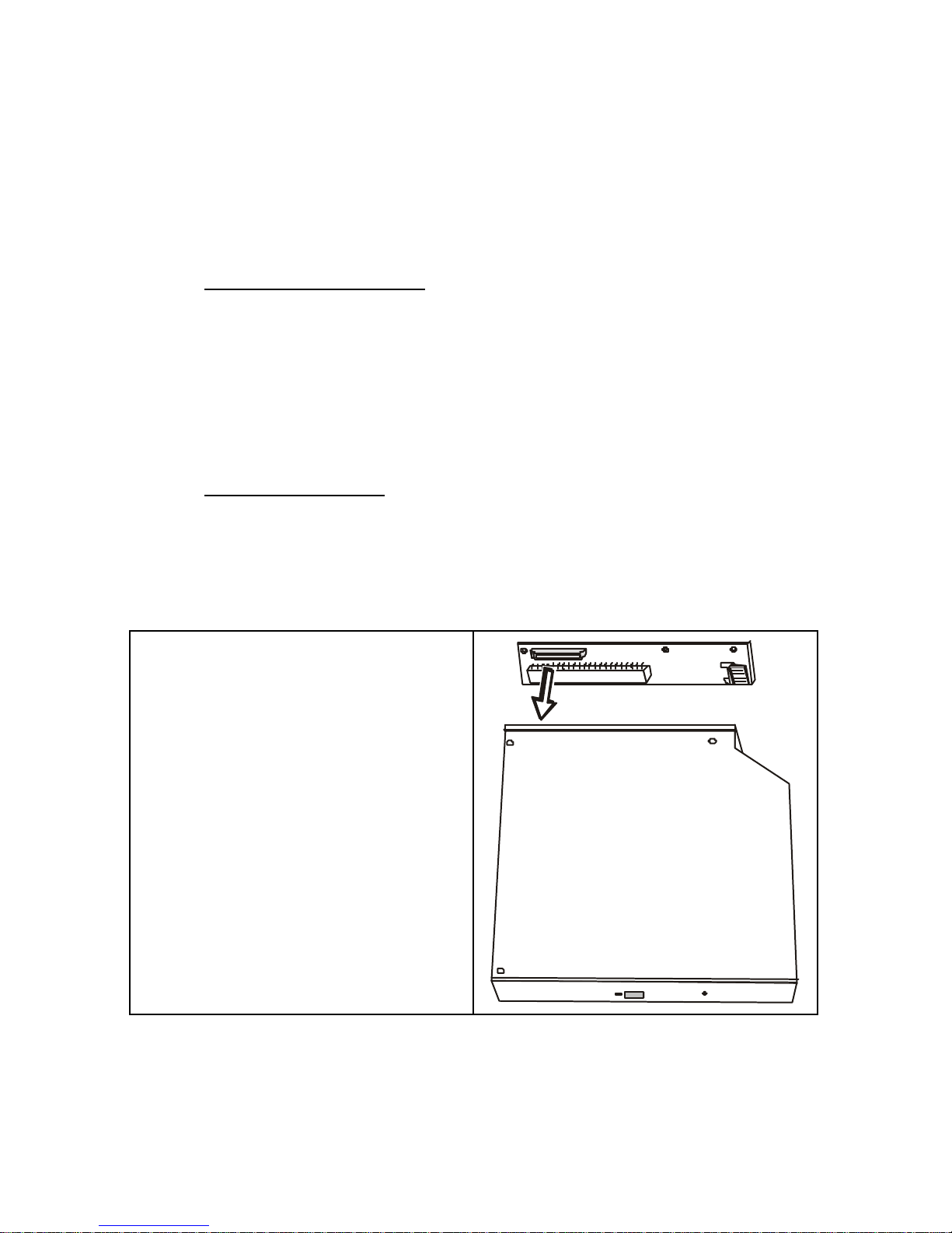
AAttttaacchhiinngg tthhee CCDD--RROOMM
To install a CD-ROM drive in your PT-4000 POS Station, refer to the
following:
Components Required
• Slim-type CD-ROM drive
• Control PCB
• CD-ROM plates (center, right, left)
• M2.0*3 screws x 7
• M3*6 screws x 8
Before Proceeding
Remove the Rear Cover (see page 14).
Remove the Front Cover (see page 15).
1. Attach the control PCB to the back
of the CD-ROM drive:
Page 28
18
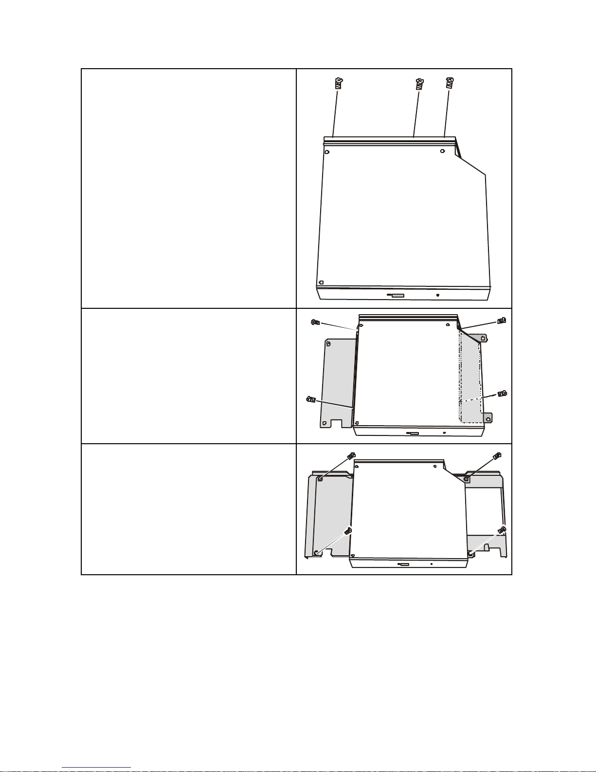
2. Secure the PCB to the CD-ROM
drive with three M2.0*3 screws:
3. Secure the right and left plates to
the CD-ROM drive with four
M2.0*3 screws:
4. Secure the CD-ROM drive right
and left plates to the center plate
with four M3*6 screws:
Page 29
19
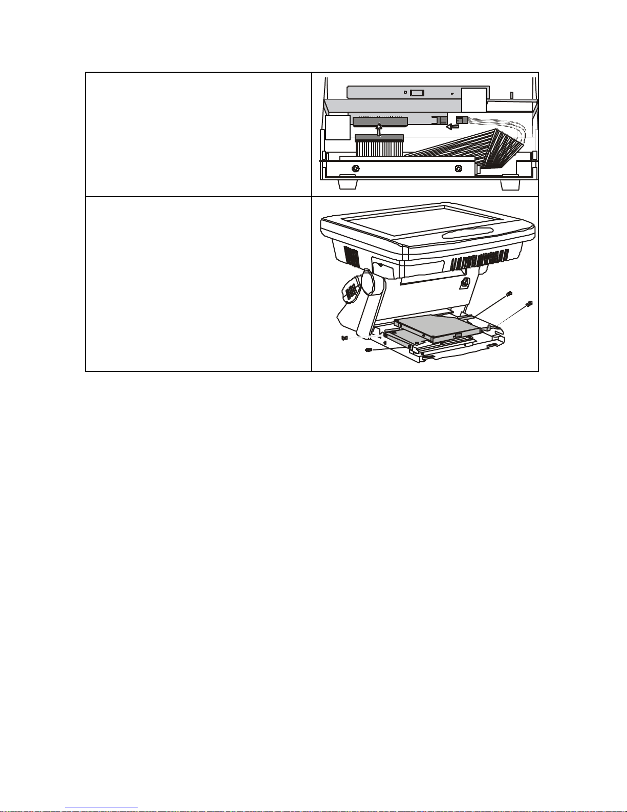
5. Connect the CD-ROM cable to the
CD-ROM drive connector (A).
Connect a power cable to the
PCB board (B):
6. Secure the CD-ROM drive to the
system base with four M3*6
screws:
Replace the Front Cover.
Replace the Rear Cover.
A B
Page 30
20
AAttttaacchhiinngg tthhee FFllooppppyy DDiisskk DDrriivvee
To install a Floppy Disk Drive (FDD) in your PT-4000 POS Station, refer
to the following:
Components Required
• Slim-type FDD
• FDD cable
• Control PCB and PCB cable
• FDD center and holding plates
• M2.0*3 screws x 4
• M3*6 screws x 8
Before Proceeding
Remove the Rear Cover (see page 14).
Remove the Front Cover (see page 15).
Remove the CD-ROM if installed (see page 17).
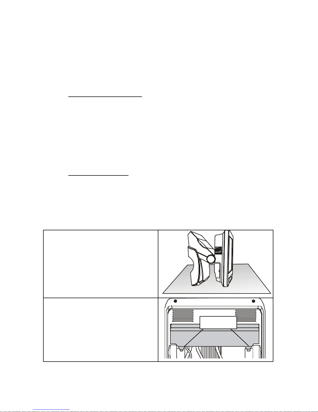
1. Carefully place the POS on a
stable surface as shown:
2. There are two latches on the IDE
access cover; you may have to
adjust the base to clear these
latches when opening the IDE
access cover:
Latches
Page 31
21
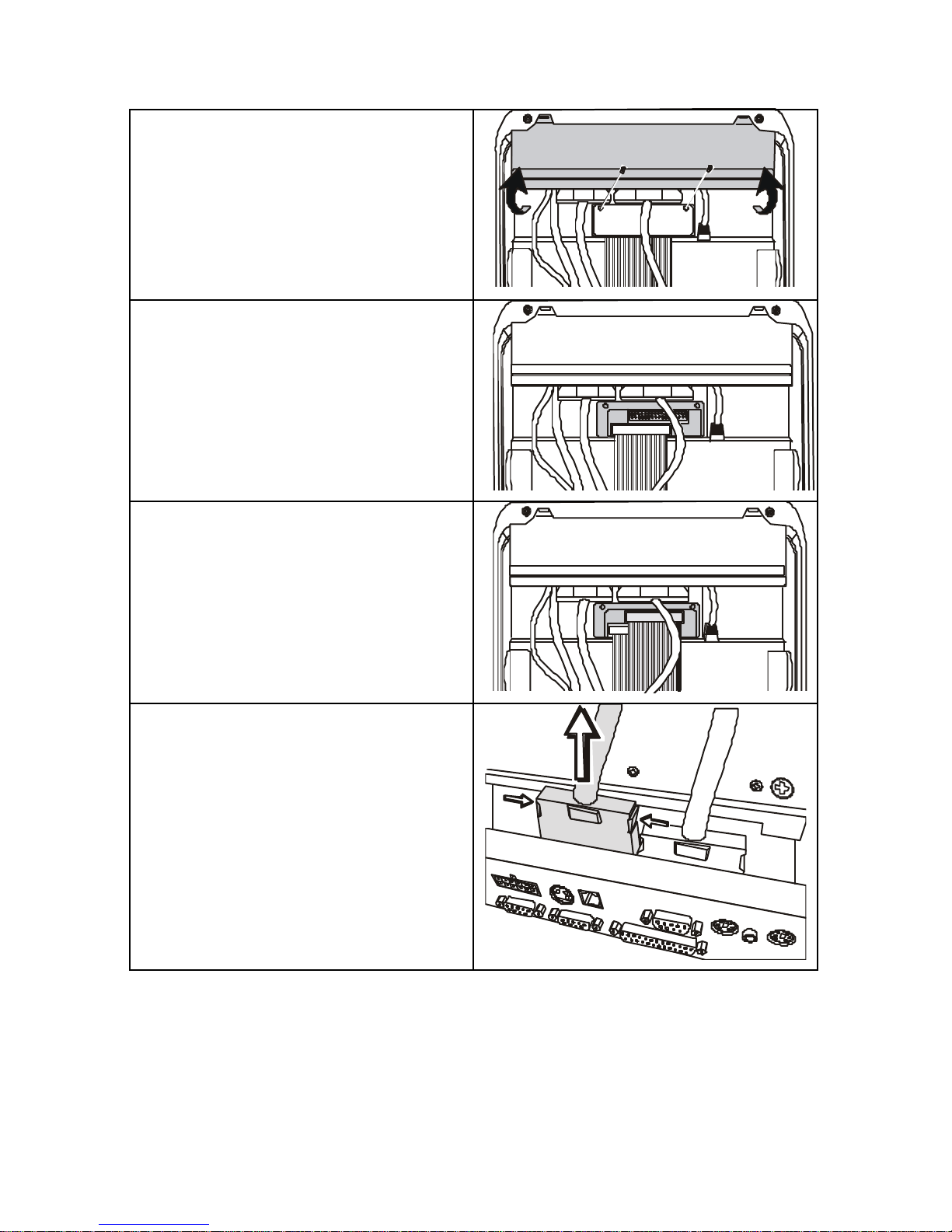
3. Open the IDE access cover and
remove the two screws from the
IDE connector cover:
4. Remove the IDE connector cover:
5. Connect the FDD cable to the
FDD connector:
Note! Pin 1 on the cable is marked with
a red stripe.
6. Replace the IDE connector cover:
7. Disconnect the video cable by
pushing on the sides of the
connector as shown and then
lifting up:
Page 32
22
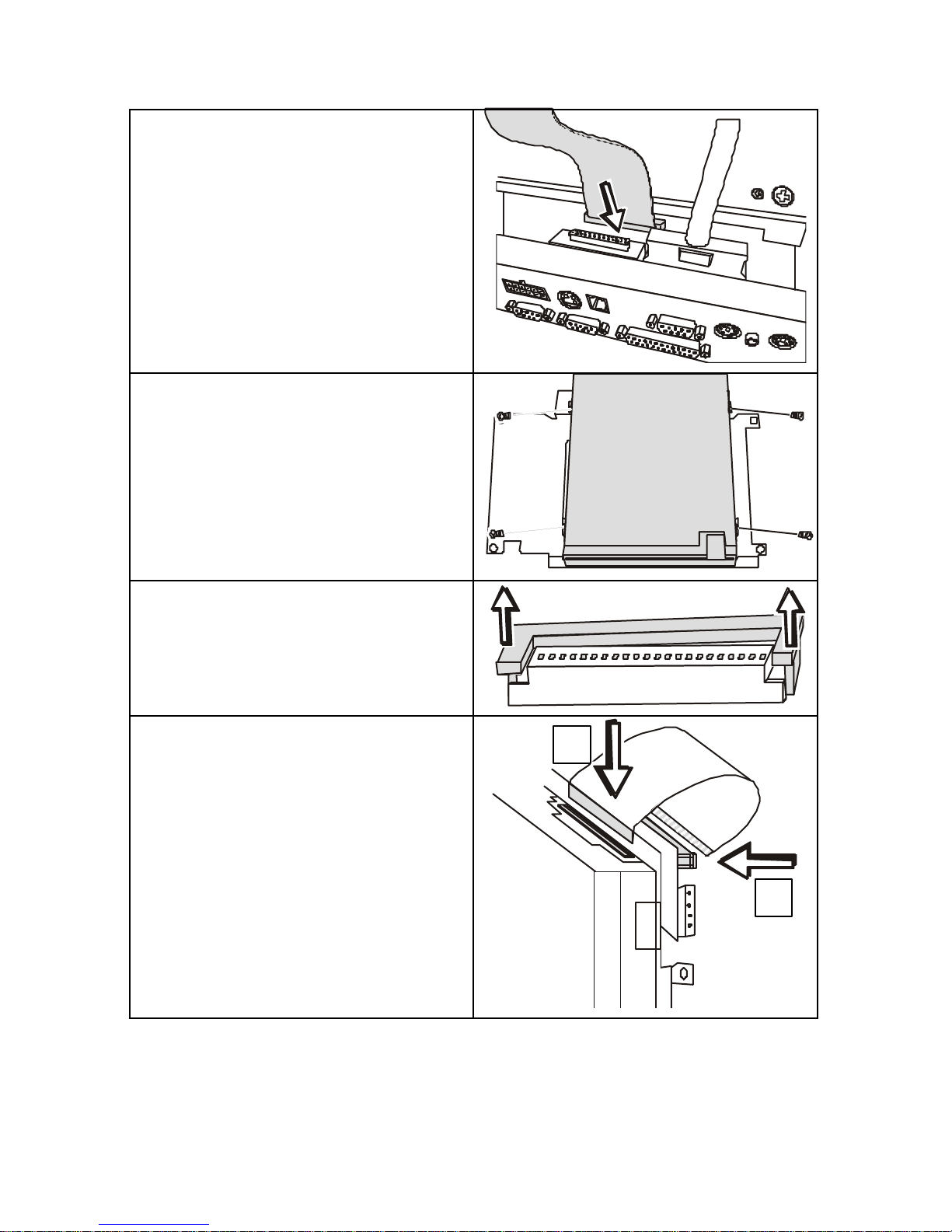
8. Pass the FDD cable through the
opening as shown and reconnect
the video cable:
9. Secure the holding plate to the
FDD with four M2.0*3 screws:
10. Unlock the IPC safety locks on the
FDD and the PCB board by lifting
up at the sides as shown here:
11. Connect the IPC cable to the FDD
and lock the IPC saf ety lock (A).
Connect the other end of the IPC
cable to the control PCB and lock
the IPC safety lock (B):
A
B
Page 33
23
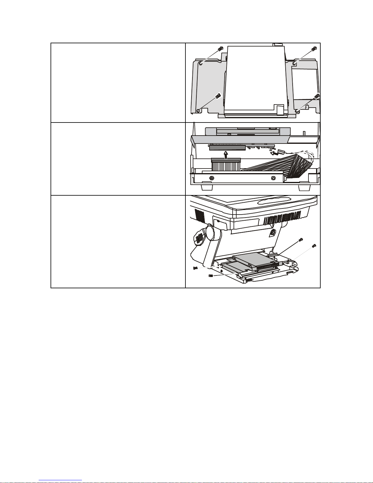
12. Attach the FDD to the center plate
with four M3*6 screws:
13. Connect the FDD cable and a
power cable to the PCB board:
14. Secure the FDD to the system
with four M3*6 screws:
Replace the Front Cover.
Replace the Rear Cover.
Page 34
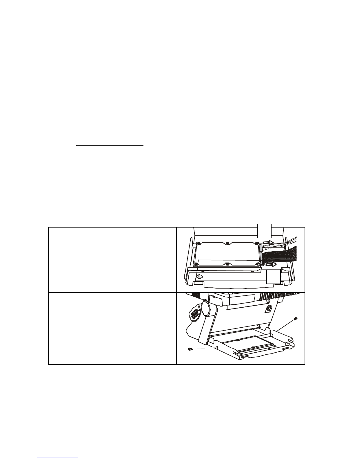
24
RReeppllaacciinngg tthhee HHaarrdd DDiisskk DDrriivvee
To upgrade the Hard Disk Drive (HDD) on your PT-4000 POS Station,
refer to the following:
Components Required
Replacement HDD
Before Proceeding
Remove the Rear Cover (see page 14)
Remove the Front Cover (see page 15)
Remove the CD-ROM if installed (see page 17)
Remove the FDD if installed (see page 20)
1. Disconnect the power cable (A)
and the IDE cable (B):
2. Remove the two screws that
secure the HDD base plate:
A B
Page 35
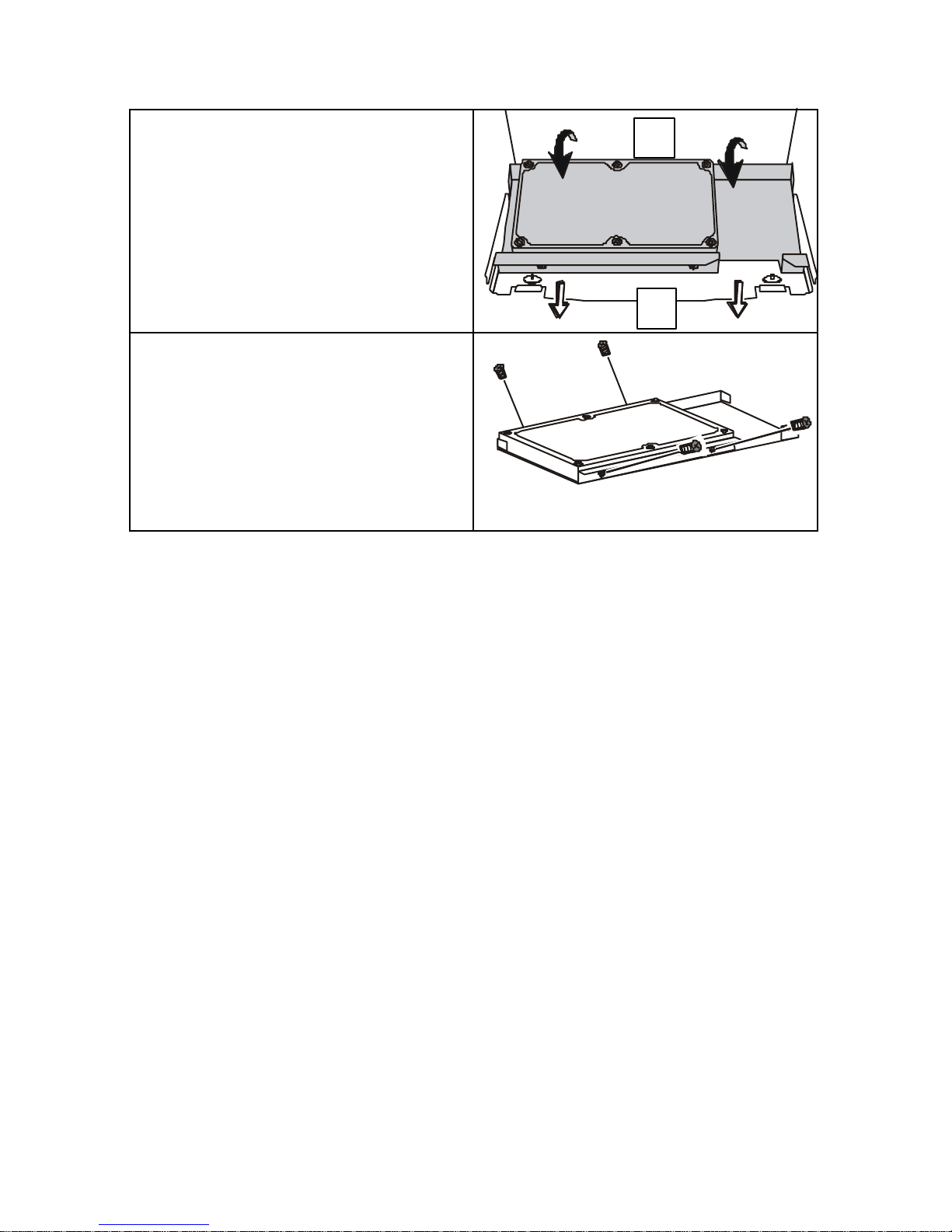
25
3. To remove the HDD and base
plate, lift up at the rear of the base
plate (A), then away from the
system (B):
4. Remove the four sc rews that
secure the HDD to the base plate:
Reverse the above procedure to install the new HDD.
Replace the Front Cover.
Replace the Rear Cover.
A
B
Page 36
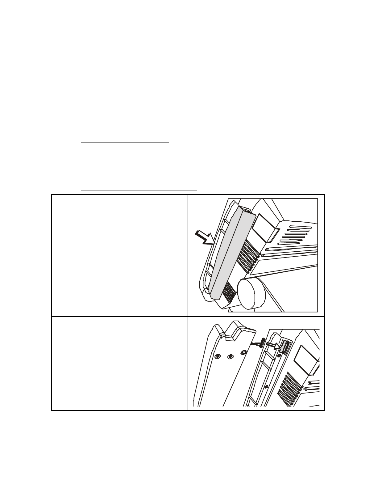
26
AAttttaacchhiinngg tthhee MMaaggnneettiicc SSttrriipp RReeaaddeerr
To install a Magnetic Strip Reader (MSR) on your PT-4000 POS Station,
refer to the following:
Note! The MSR can be configured as a side-swipe or front-swipe unit.
Components Required
• M3*10 screws x 2
• MSR x 1
Front-swipe MSR Installation
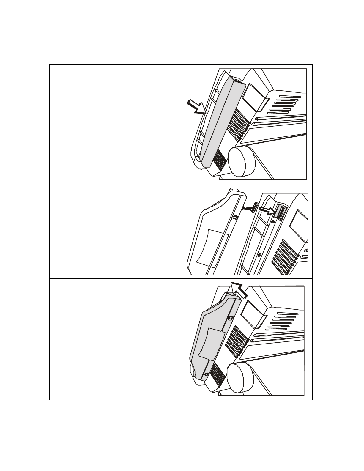
1. Remove the cover plate on the
right side of the LCD panel as
shown:
2. Connect the MSR cable. Ensure
that it is attached securely:
Page 37
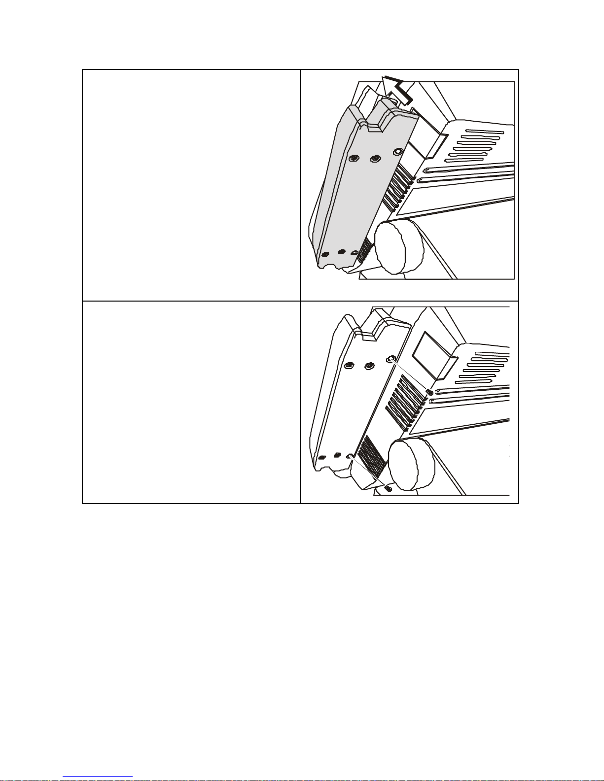
27
3. Attach the MSR unit to the LCD
panel. Ensure that the cable is
folded inside the opening:
4. Secure the MSR unit to the LCD
panel with two M3*10 screws:
Page 38
28
Side-swipe MSR Installation
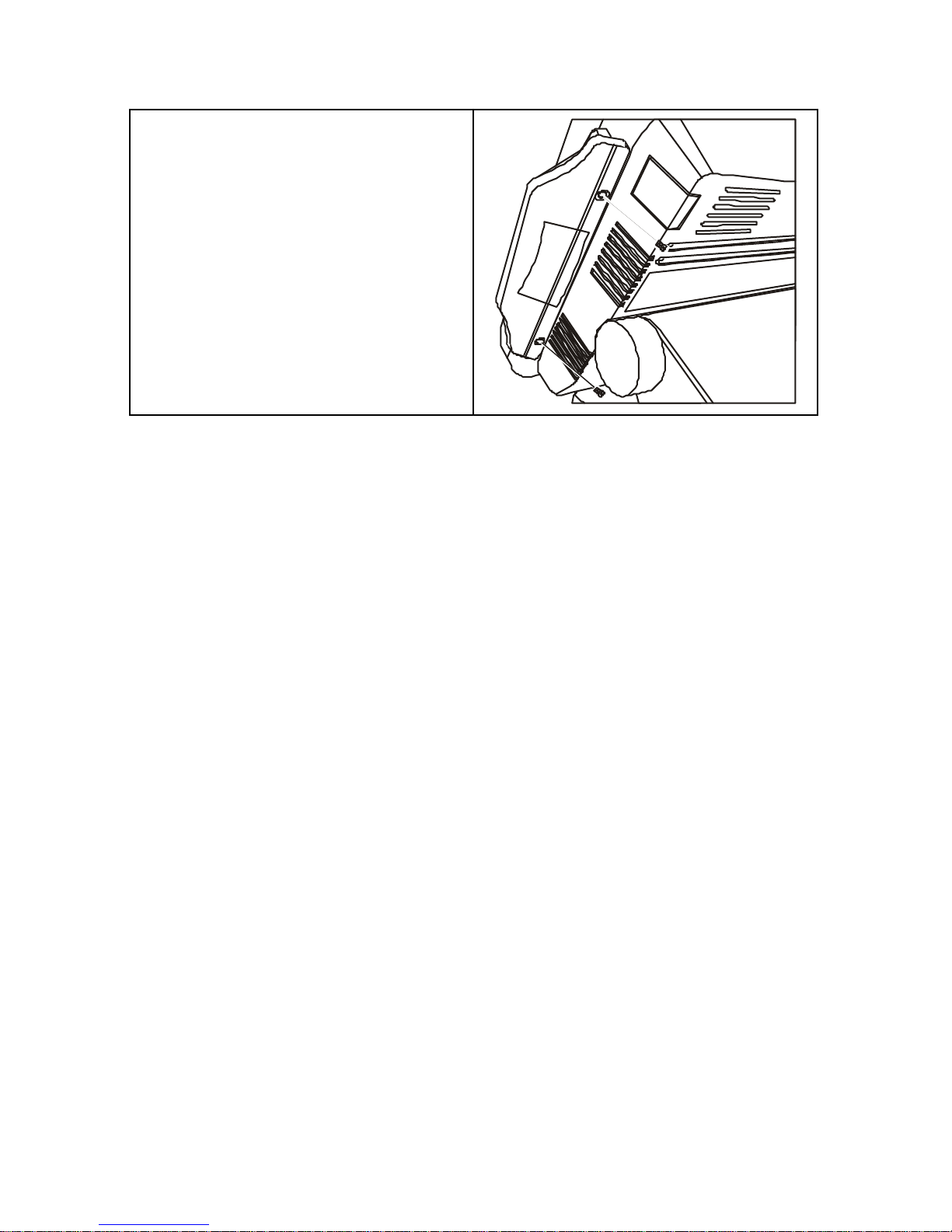
1. Remove the cover plate on the
right side of the LCD panel as
shown:
2. Connect the MSR cable. Ensure
that it is attached securely:
3. Attach the MSR unit to the LCD
panel. Ensure that the cable is
folded inside the opening:
Page 39
29
4. Secure the MSR unit to the LCD
panel with two M3*6 screws:
Page 40

30
AAttttaacchhiinngg tthhee RReeaarr CCuussttoommeerr DDiissppllaayy
To install a Rear Customer Display to your PT-4000 POS Station, refer to
the following:
Components Required
• M3*8 screws x 2
• Rear Customer Display
• Display backplate
• Cable
Before Proceeding
Remove the Rear Cover (see page 14)
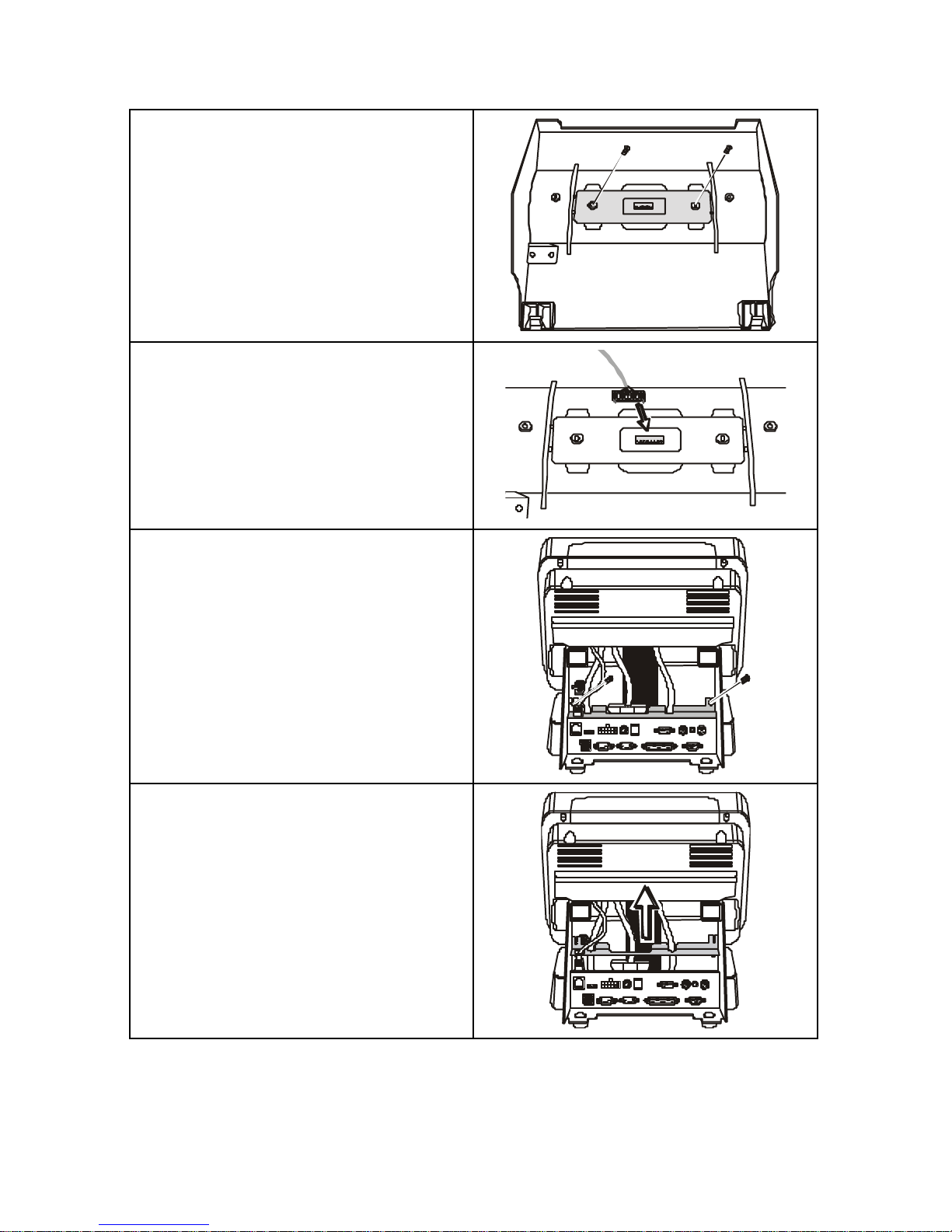
1. Turn the cover over and remove
the two screws to separate the
dummy cover from the rear cover:
2. Ensure that the display unit is
oriented in the correct direction
with the display backplate to the
inside of the cover as shown:
Page 41
31
3. Secure the display to the rear
cover with two M3*8 screws:
4. Connect the display cable (the
cable is keyed to only connect one
way):
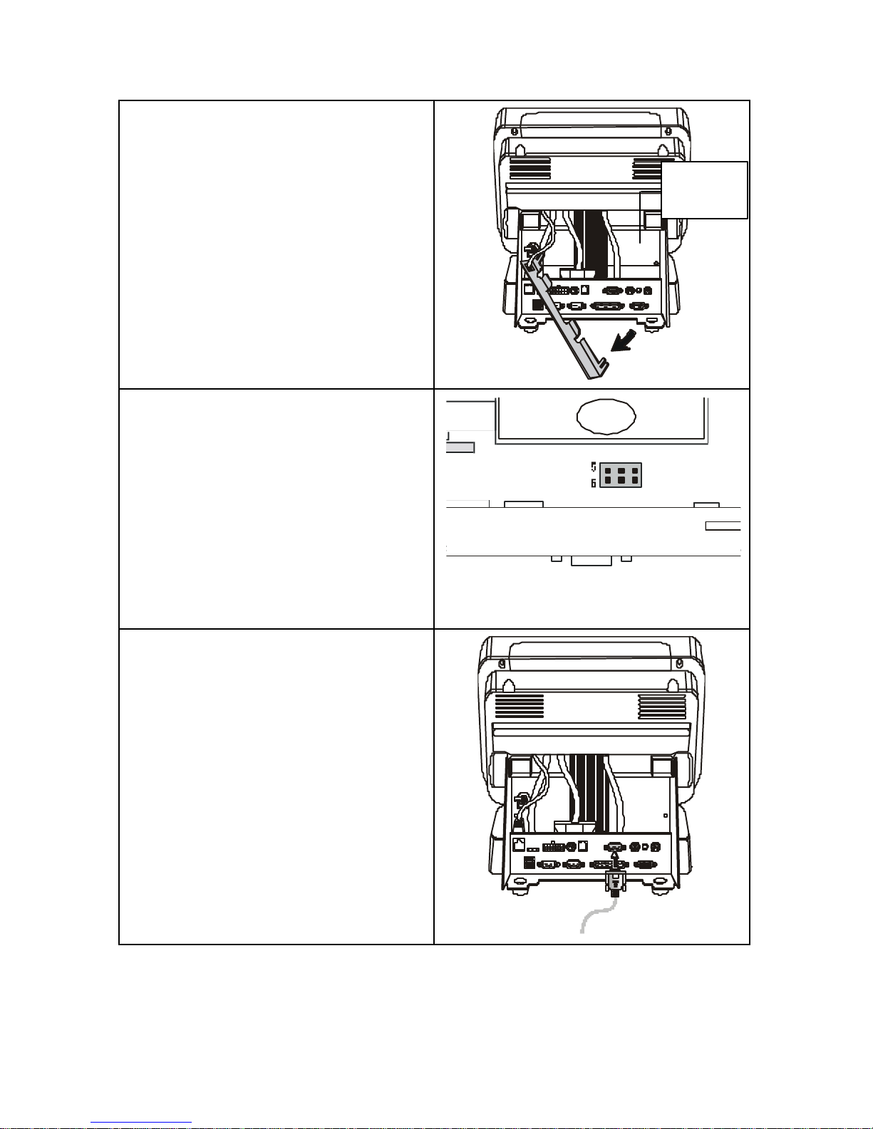
5. At the rear of the POS, remove
the two screws from the PCB
board cover:
6. Lift the PCB board cover:
Page 42
32
7. Move the PCB board cover to the
side and locate the PCB board.
8. Short pins 5-6 (DC 12V) of the
Power PCB jumper JP1. Replace
the PCB board cover and secure it
with the two screws: (See
Appendix C for more information
on jumper locations.)
P11
JP112
9. Connect the display cable to COM
3:
Replace the Rear Cover.
PCB
board
Page 43
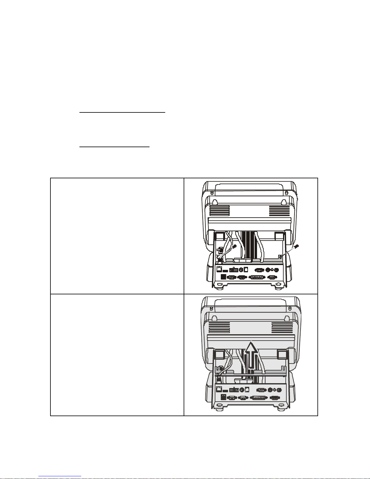
33
AAttttaacchhiinngg tthhee CCuussttoommeerr PPoollee DDiissppllaayy
You can connect the Customer Pole Dis play to COM 3 if you prefer to
use it instead of the Rear Customer Display: Refer to the following:
Components Required
• Customer Pole Display
Before Proceeding
Remove the Rear Cover (see page 14)
1. Remove the two screws from the
PCB board cover:
2. Lift the PCB board cover:
Page 44
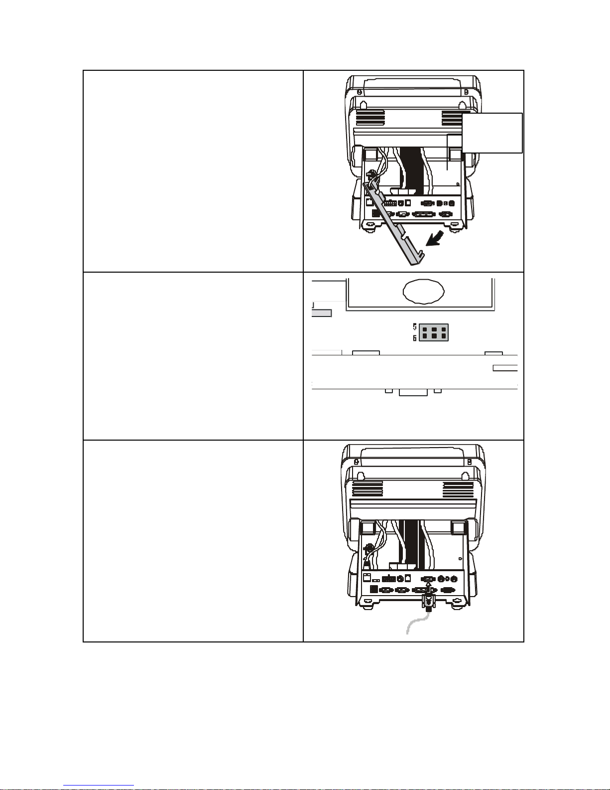
34
3. Move the PCB board cover to the
side and locate the PCB board.
4. Short pins 5-6 (DC 12V) of the
Power PCB jumper JP1 (see
Appendix C for the jumper
location). Replace the PCB board
cover and secure it with the two
screws:
P11
JP112
5. Connect the display cable of the
Customer Pole Display to COM 3:
Replace the Rear Cover.
PCB
board
Page 45
35
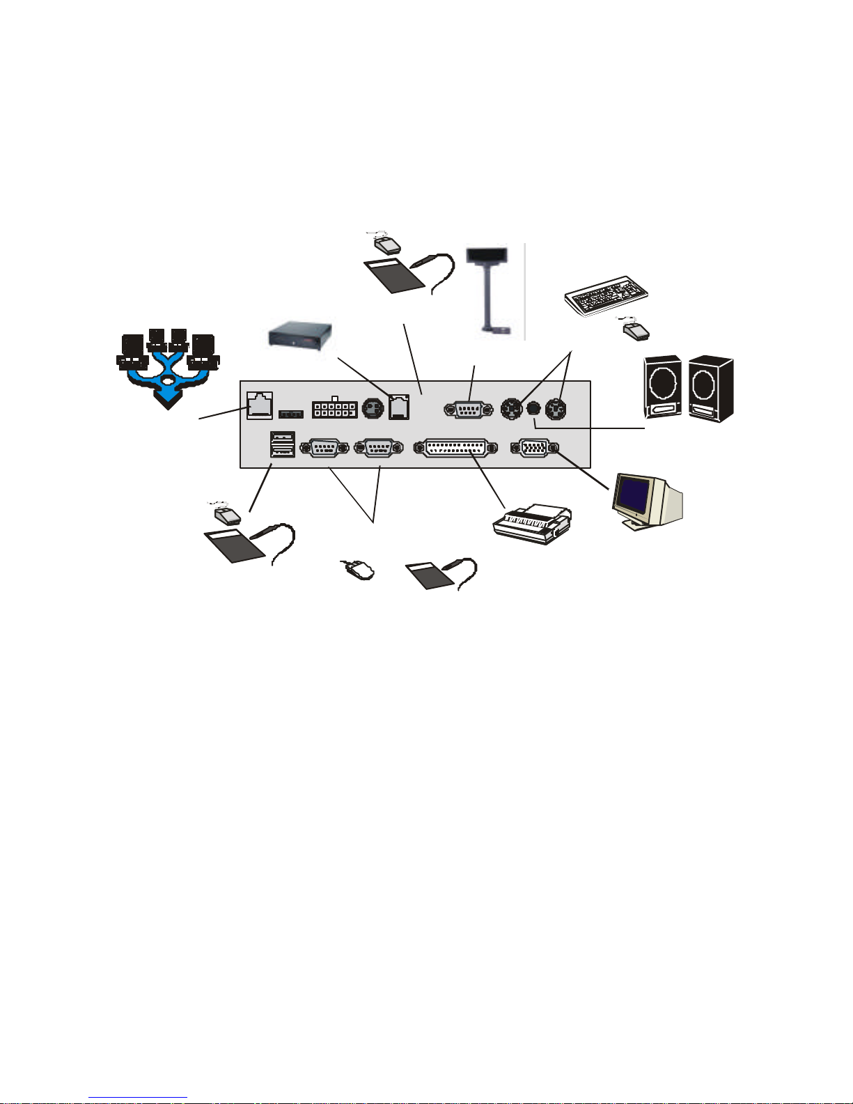
CCoonnnneeccttiinngg II//OO ddeevviicceess
The PT-4000 POS Station supports many peripheral devices to expand the
functionality of the station:
USB
5V/12VNET 24V/OUTPOWER IN
CASH
DRAWER
COM3 MOUSEKBSPK
COM1 COM2 PRINTER VGA
USB
Compliant
Device
Network
(LAN)
USB
Compliant
Device
Printer
External
Monitor
External
Speakers
Graphics
Tablet
Serial
Mouse
or
PS/2 Mouse/
Keyboard
Rear Customer/Pole
Display
Cash Drawer
Figure 7 – Connecting peripheral devices
Note! The PT-4000 POS Station does not have the USB ports located near
the cash drawer port.
Page 46
36
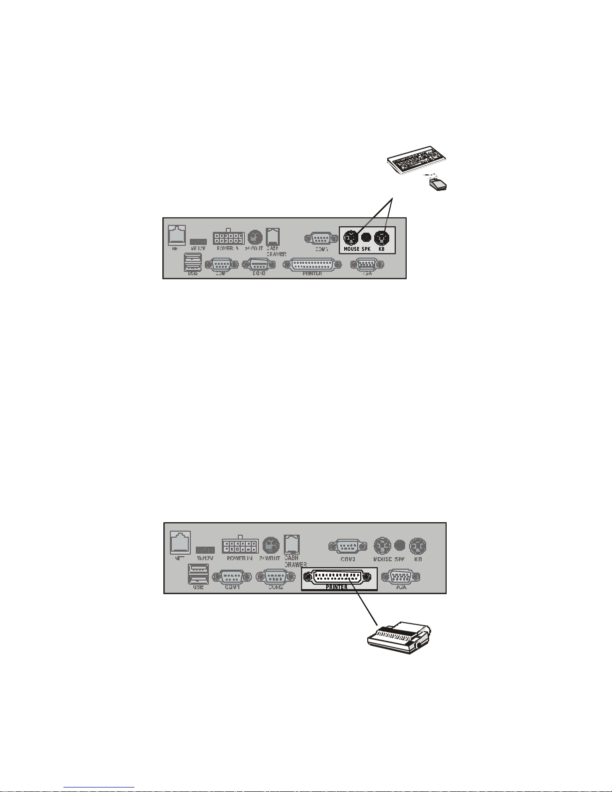
CCoonnnneeccttiinngg aa PPSS//22 KKeeyybbooaarrdd aanndd MMoouussee
Connect a keyboard and mouse to the PS/2 keyboard and mouse ports.
USB
5V/12VNET
24V/OUTPOWER IN CASH
DRAWER
COM3 MOUSE
KBSPK
COM1 COM2 PRINTER VGA
PS/2 Mouse/
Keyboard
Figure 8 – Connecting a PS/2 mouse or keyboard
The keyboard can be connected even if you have installed the optional IR
keyboard.
Note! If your keyboard has an AT type connector, you must use an adapter.
Contact your dealer for details.
You can also connect a CCD (barcode scanner) to the PS/2 keyboard
port.
CCoonnnneeccttiinngg aa PPrriinntteerr
Connect a printer to the standard 25-pin D-type parallel connector on the
I/O ports.
USB
5V/12VNET
24V/OUTPOWER IN CASH
DRAWER
COM3 MOUSE
KBSPK
COM1 COM2 PRINTER VGA
Printer
Figure 9 – Connecting a printer
Page 47
37
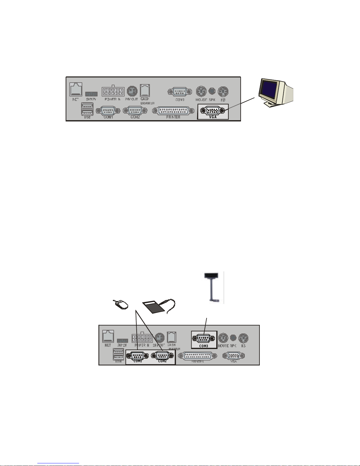
CCoonnnneeccttiinngg aa VVGGAA MMoonniittoorr
You can connect an auxiliary VGA display to the VGA port.
USB
5V/12V
NET
24V/OUTPOWER IN CASH
DRAWER
COM3 MOUSEKBSPK
COM1 COM2 PRINTER VGA
External
Monitor
Figure 10 – Connecting an external monitor
Refer to Windows online help for more information on using multiple
monitors.
CCoonnnneeccttiinngg SSeerriiaall DDeevviicceess
Connect serial devices to the 9-pin D-type serial ports on the I/O port
array. You can connect a CCD barcode scanner or Smart Card reader to
these ports.
Caution! These serial ports are voltage selectable and can cause
damage to external devices if not set up correctly. Refer
to the Appendix for serial port voltage settings.
USB
5V/12VNET
24V/OUTPOWER IN
CASH
DRAWER
COM3 MOUSE
KBSPK
COM1 COM2 PRINTER VGA
Graphics
Tablet
Serial
Mouse
or
Rear Customer/Pole
Display
Figure 11 – Connecting a serial device
Note! Refer to Attaching the Rear Customer Display (page 30) and
Attaching the Customer Pole Display (page 33) for more information.
Page 48
38
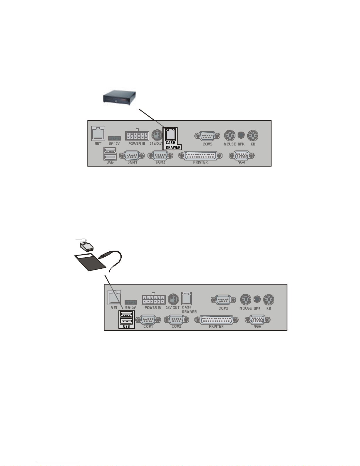
CCoonnnneeccttiinngg aa CCaasshh DDrraawweerr
Connect the cash drawer RJ-11 connector to the RJ-11 port on the I/O
port array.
USB
5V/12VNET
24V/OUTPOWER IN
CASH
DRAWER
COM3 MOUSE
KBSPK
COM1 COM2 PRINTER VGA
Cash Drawer
Figure 12 – Connecting a cash drawer
CCoonnnneeccttiinngg UUSSBB DDeevviicceess
Connect USB devices to the USB ports on the I/O port array:
USB
5V/12VNET 24V/OUTPOWER IN
CASH
DRAWER
COM3 MOUSE KBSPK
COM1 COM2 PRINTER VGA
USB
Compliant
Device
Figure 13 – Connecting USB devices
Page 49
39
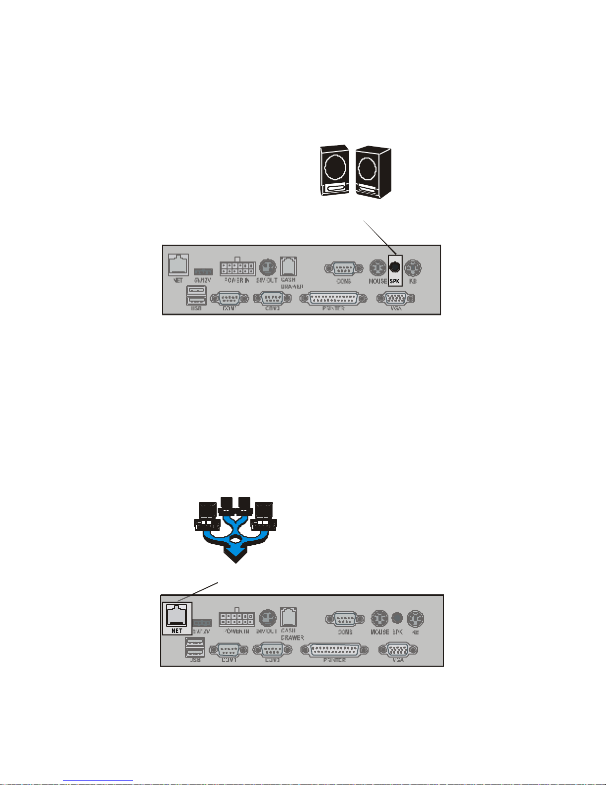
CCoonnnneeccttiinngg SSppeeaakkeerrss
Connect stereo speakers to the speaker jack on the I/O port array:
USB
5V/12VNET
24V/OUTPOWER IN
CASH
DRAWER
COM3 MOUSE
KBSPK
COM1 COM2 PRINTER VGA
External
Speakers
Figure 14 – Connecting stereo speakers
Note! You must install the audio driver before you can listen to audio output
with the speakers.Installing Audio on page 錯誤! 尚未定義書籤。.
CCoonnnneeccttiinngg ttoo aa LLAANN
Connect a 10/100 Base-T Ethernet LAN to the RJ -45 jack on the I/O port
array:
USB
5V/12VNET
24V/OUTPOWER IN
CASH
DRAWER
COM3 MOUSE
KBSPK
COM1 COM2 PRINTER VGA
Network
(LAN)
Figure 15 – Connecting to the LAN
Page 50
40
SSttaarrttiinngg tthhee SSyysstteemm
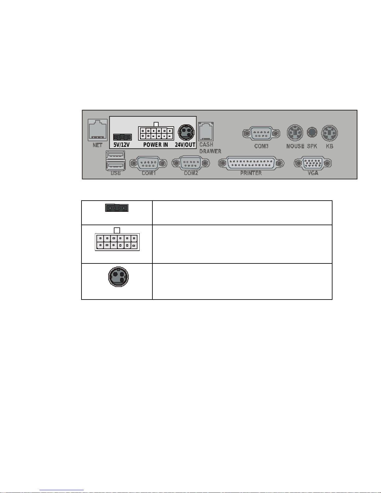
CChheecckkiinngg tthhee PPoowweerr SSuuppppllyy
Connect the power supply cables to the power jacks on the I/O port
array:
USB
5V/12VNET 24V/OUTPOWER IN
CASH
DRAWER
COM3 MOUSE KBSPK
COM1 COM2 PRINTER VGA
5V/12V
+5/12V power supply for optional FDD, HDD, or
CD-ROM drive
POWER IN
AC adapter power cable plug
24V/OUT
+24V power supply for 24 volt devices
Page 51
41
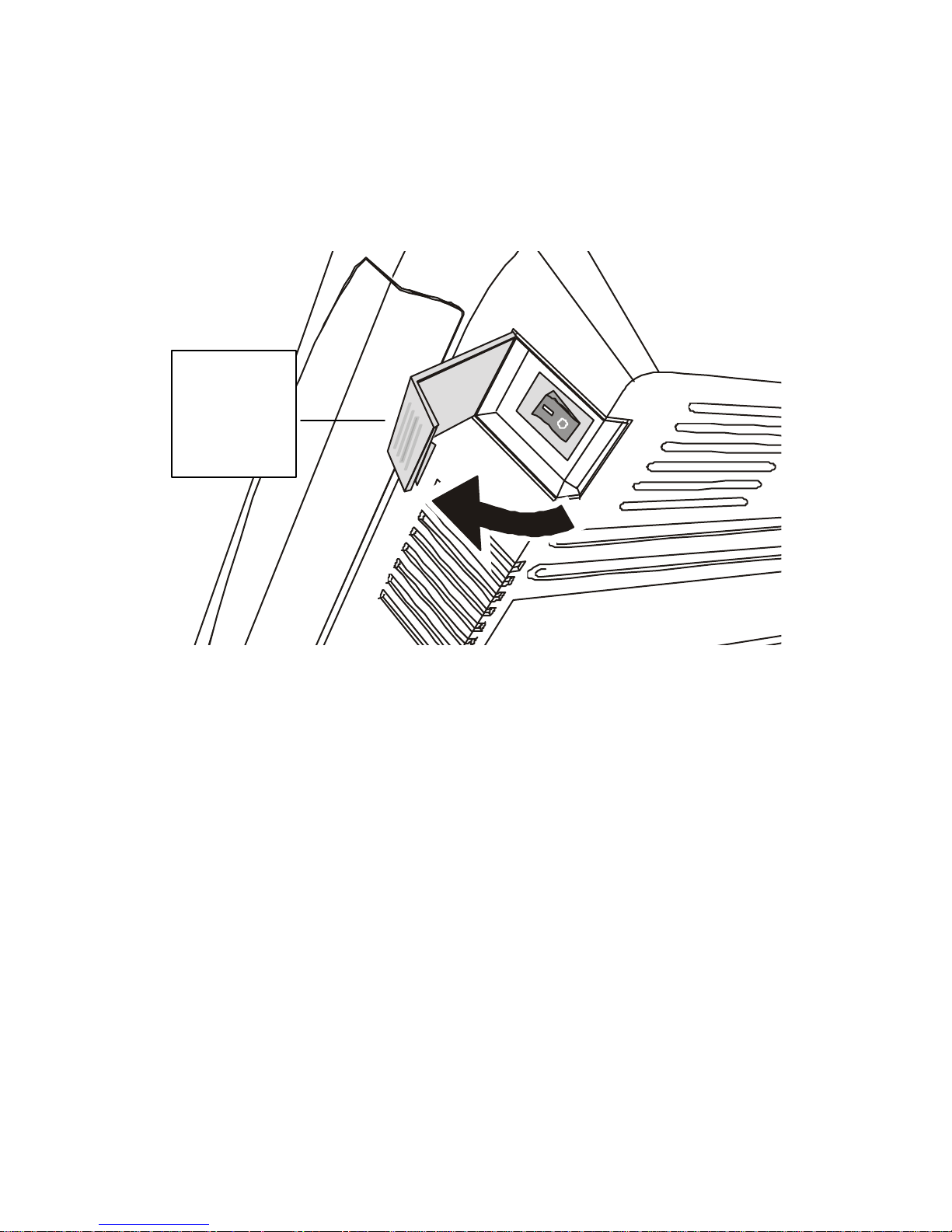
TTuurrnniinngg tthhee SSyysstteemm OOnn
Open the power switch cover and press the power switch to turn the
system on:
Figure 16 – Turning the system on
Open the
cover and
press the
power
switch
Page 52
42
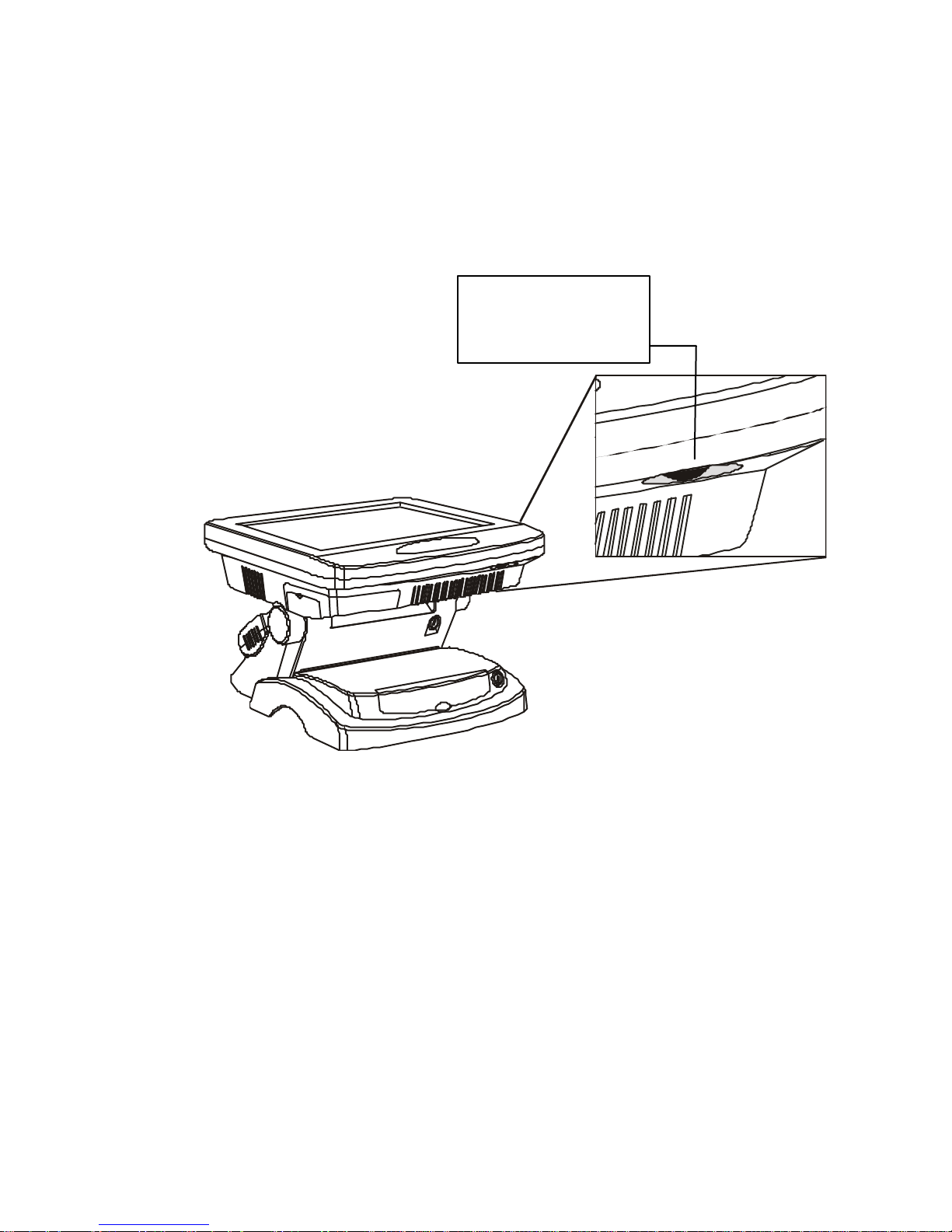
AAddjjuussttiinngg tthhee DDiissppllaayy BBrriigghhttnneessss
As the system powers on, turn the dial located at the base of the LCD
panel to adjust the display brightness for optimum viewing:
Figure 17 – Adjusting display brightness
Turn the dial to
adjust the display
brightness.
Page 53
CChhaapptteerr 33:: IInnssttaalllliinngg DDrriivveerrss aanndd SSooffttwwaarree
This section explains how to install the drivers for the PT4000 POS
Station VGA, audio, LAN, Touchscreen, modem, and utilities.
PPTT44000000 DDrriivveerr IInnssttaallllaattiioonn
This section covers the installation of software for the PT-4000 POS
Station.
AAuuttooiinnssttaallllaattiioonn
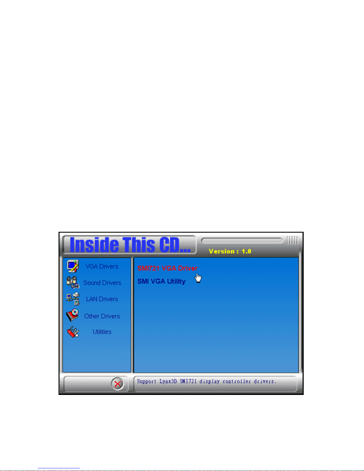
The PT-4000 POS Station comes with an autoinstall CD that will install
the drivers for the station.
Insert the autoinstall CD into your CD -ROM drive. The following screen
appears:
Page 54

44
Install VGA Drivers Installs video drivers for Windows 2000,
ME/98/95, and NT4.0
Sound Drivers Installs audio drivers for Windows 2000,
ME/98/95, and NT4.0
LAN Drivers Installs LAN drivers for Windows 2000,
ME/98/95, and NT4.0
Other Drivers Installs for the Touchscreen, modem,
OPOS, camera, and IC card
Utilities Installs software for a cash drawer,
CD7220, MSR, and speaker
Click the buttons and follow the instructions on the screen to install
drivers, read installation instructions, or open the manufacturer’s Web site.
Note! If the screen doesn’t automatically appear, you have the Auto insert
notification turned off in the Device Manager. Click Start, Settings,
Control Panel, and double-click the System icon. Click the Device
Manager tab and expand the CD-ROM item. Double-click your CDROM drive entry and click settings. Ensure that Auto insert
notification is checked.
Alternatively, browse to the CD-ROM root directory and double-click
Autorun.exe.
Page 55

45
MMaannuuaall IInnssttaallllaattiioonn
This section explains how to install the device drivers manually.
Installing VGA Drivers
Follow these instructions to install VGA device drivers for Windows
2000/ME/98/95/NT4.0:
Windows 2000
1. Insert the driver CD into the CD-ROM drive.
2. Click Start, Run.
3. Type “D: \VGA\PANEL\WIN2000” in the Run Open dialog box,
where D is your CD-ROM drive.
4. Click OK.
5. Follow the instructions on the screen to install the Windows 2000
VGA driver.
Windows ME/98/95
1. Insert the driver CD into the CD-ROM drive.
2. Click Start, Run.
3. Type “D: \VGA\PANEL\WIN95” in the Run Open dialog box, where
D is your CD-ROM drive.
4. Click OK.
5. Follow the instructions on the screen to install the Windows
ME/98/95 VGA driver.
Windows NT4.0
1. Insert the driver CD into the CD-ROM drive.
2. Click Start, Settings, and Control Panel.
3. Double-click the Display icon.
4. Select the Settings tab in the Display Properties dialog box.
5. Click the Display Type button.
6. Click the Adapter Type tab and click the Change button.
7. Follow the instructions on the screen. When you are prompted to
choose the location of the driver, click Have Disk.
8. Type “D: \VGA\PANEL\WINNT40” in the Install from Disk dialog
box, where D is your CD-ROM drive.
9. Click OK.
Page 56

46
10. When the Change Display dialog box appears, click OK.
11. When the Third-party Drivers dialog box appears, click Yes.
Installing VGA Utilities
Follow these instructions to install VGA device drivers for Windows
2000/ME/98/95/NT4.0 and Linux:
Windows 2000
1. Insert the driver CD into the CD-ROM drive.
2. Click Start, Run.
3. Type “D: \VGA\SMI721\WIN2000” in the Run Open dialog box,
where D is your CD-ROM drive.
4. Click OK.
5. Follow the instructions on the screen to install the Windows 2000
VGA driver.
Windows ME/98/95
1. Insert the driver CD into the CD-ROM drive.
2. Click Start, Run.
3. Type “D: \VGA\SMI721\WIN95” in the Run Open dialog box, where
D is your CD-ROM drive.
4. Click OK.
5. Follow the instructions on the screen to install the Windows
ME/98/95 VGA driver.
Windows NT4.0
1. Insert the driver CD into the CD-ROM drive.
2. Click Start, Settings, and Control Panel.
3. Double-click the Display icon.
4. Select the Settings tab in the Display Properties dialog box.
5. Click the Display Type button.
6. Click the Adapter Type tab and click the Change button.
7. Follow the instructions on the screen. When you are prompted to
choose the location of the driver, click Have Disk.
8. Type “D: \VGA\SMI721\WINNT40” in the Install from Disk dialog
box, where D is your CD-ROM drive.
9. Click OK.
10. When the Change Display dialog box appears, click OK.
11. When the Third-party Drivers dialog box appears, click Yes.
Page 57

47
Linux
Refer to the readme.txt and the SMI App Note - Linux installation guide
for Lynxfamily.doc located in the directory D:\ VGA \SMI721\LINUX\
(where D is your CD-ROM drive) for information on setting up the
display utility in the Linux operating system.
Installing Audio
Follow these instructions to install audio device drivers for Windows
2000/ME/98/95NT4.0 and DOS:
Windows 2000
Insert the driver CD into the CD-ROM drive.
1. Click Start, Run.
2. Type “D: \SOUND\ESS1938\WIN2000” in the Run Open dialog box,
where D is your CD-ROM drive.
3. Follow the instructions on the screen to install the audio driver for
the Windows 2000 operating system.
Windows ME/98/95
Insert the driver CD into the CD-ROM drive.
1. Click Start, Run.
2. Type “D: \SOUND\ESS1938\WIN95” in the Run Open dialog box,
where D is your CD-ROM drive.
3. Follow the instructions on the screen to install the audio driver for
the Windows ME/98/95 operating systems.
Windows ME/2000/98/95/NT
Insert the driver CD into the CD-ROM drive.
1. Click Start, Run.
2. Type “D: \SOUND\ESS1938\WINNT40” in the Run Open dialog
box, where D is your CD-ROM drive. The setup program
automatically detects your operating system.
3. Follow the instructions on the screen to install the audio driver for
your Windows operating system.
Page 58

48
Installing LAN
Follow these instructions to install LAN device drivers for Windows
ME/2000/98/95/NT4.0:
Note! For further instruc tions on installing the LAN drivers and associated
software, check the Readme.txt file in the operating system subdirectory
for information about installing the LAN driver for a particular OS.
Windows ME/2000/98/95/NT
1. Insert the driver CD into the CD-ROM drive.
Note! For Windows 9X: If the Operating System’s New Hardware Wizard
prompts you that New Hardware Found for the PCI Ethernet
Controller, click Next until you have completed the wizard. (Do not
specify the location of the driver). The PCI Ethernet Controller is
displayed in the Device Manager. Then you can install the driver as
shown in the following steps.
2. Click Start, Run.
3. Type “D: \LAN\RTL8139X\RSET8139.EXE” in the Run Open dialog
box, where D is your CD-ROM drive. The setup program
automatically det ects your operating system.
4. Follow the instructions on the screen to install the LAN driver for
your Windows operating system.
Page 59

49
OOtthheerr DDrriivveerrss aanndd UUttiilliittiieess
This section provides a description of the items Other Drivers and
Utilities located on the CD-ROM.
Other Drivers
Drivers are provided for optional items to enhance your PT-4000 POS
Station:
Camera Driver
Windows 2000/95 camera drivers are provided for use with video capture
hardware such as a digital camera, enabling users to take customer photos
for records and store them on the POS unit.
Browse to the Windows operating system subfolder and run Setup.exe to
install the driver.
IC Card Driver
Windows 2000/95 drivers are provided for an optional IC Card Reader.
The reader is attached to the PT-4000 POS Station via a serial interface
(COM port 1, 2 or 3).
Browse to the Windows operating system subfolder and run Setup.exe to
install the driver.
Modem Driver
Follow these instructions to install the modem device drivers for
Windows ME/2000/98/95/NT4.0:
Windows 2000
1. Insert the driver CD into the CD-ROM drive.
2. Click Start, Settings, then click Control Panel .
3. Double-click the Phone and Modem Options icon.
4. Enter the information in the Location Information dialog box.
5. Click the Modems tab in the Phone and Modem Opt ions dialog
box.
Page 60

50
6. Click Add. Check the box next to “Don’t detect my modem, I will
select it from a list.
7. Click Have Disk.
8. Browse to the location of the modem driver on your CD-ROM.
9. Click OK and follow the instructions on the screen to install the
modem driver for Windows 2000.
Windows ME/98/95
1. Insert the driver CD into the CD-ROM drive.
2. Click Start, Settings, then click Control Panel .
3. Double-click the Modems icon.
4. Enter the information in the Location Information dialog box.
5. Click Add. Check the box next to “Don’t detect my modem, I will
select it from a list.
6. Click Have Disk.
7. Browse to the location of the modem driver on your CD-ROM.
8. Click OK and follow the instructions on the screen to install the
modem driver for Windows ME/98/95.
OPOS Driver
The software and driver CD-ROM includes Windows 2000/95 OLE/POS
(OPOS) OCX drivers for the following devices:
• CD-6220 Line Display
• TP-3688 POS Printer
After installing the software for your operating system, refer to the online
Device manager help for information on using the driver with your
devices.
Page 61

51
Installing the Touchscreen
Follow these instructions to install the Elo TouchSystems Touchscreens
device drivers for Windows ME/2000/98/95:
Windows 2000
1. Insert the driver CD into the CD-ROM drive.
2. Click Start, Run.
3. Type “D: \DRIVERS\TOUCH\WIN2000\SETUP.EXE” in the Run
Open dialog box, where D is your CD-ROM drive..
4. Press OK. Follow the instructions on the screen to install the
Touchscreen driver for your Windows 2000 operating system.
5. During installation, you are prompted to select a COM port to use
with the Touchscreen. Select COM 4.
6. Click Next.
7. If the "Digital Signature Not Found" dialog is displayed by
Windows, click Yes to continue the installation. This version of
MonitorMouse for Windows 2000 has not yet been tested by
Microsoft, but has passed Elo software quality assurance tests.
8. Restart Windows when prompted.
The Touchscreen video alignment program will automatically run when
Windows starts up. Follow the instructions on the screen to align the
Touchscreen.
Windows ME/98/95
1. Insert the driver CD into the CD-ROM drive.
2. Click Start, Run.
3. Type “D: \DRIVERS\TOUCH\WIN98\SETUP.EXE” in the Run
Open dialog box, where D is your CD-ROM drive.
4. Press OK. Follow the instructions on the screen to install the
Touchscreen driver for your Windows ME/98/95 operating system.
5. During installation, you are prompted to select a COM port to use
with the Touchscreen. Select COM 4.
6. Restart Windows when prompted.
The Touchscreen video alignment program will automatically run when
Windows starts up. Follow the instructions on the screen to align the
Touchscreen.
Note! Refer to the next chapter for information on using the Touchscreen.
Page 62

52
Utilities
The following utilities are provided to enhance your PT-4000 POS Station:
Cashdraw Provides Windows 2000/95 utilities to initialize, trigger,
and provide status information for the optional cash
drawer.
Refer to the readme text file in the operating system
subfolder for command usage.
CD7220 Provides Windows 2000/98/NT utilities and software to
enable you to send text to a customer display.
Refer to the readme text file in the operating system
subfolder for command usage.
MSR Provides a Magnetic Stripe Reader (MSR) utility to adjust
MSR settings.
Refer to the readme text file in the operating system
subfolder for command usage.
Speaker Provides Windows 2000/95 utilities to test the internal
speaker.
Refer to the readme text file in the operating system
subfolder for command usage.
This concludes Chapter 3. The next chapter covers using the Touchscreen.
Page 63

CChhaapptteerr 44:: UUssiinngg tthhee TToouucchhssccrreeeenn
AAbboouutt tthhee TToouucchhssccrreeeenn
The Touchscreen enables you to use a stylus or your finger in place of a
pointing device. Before using the Touchscreen, you must install the
drivers. Refer to the previous chapter for information on installing
Touchscreen drivers.
TToouucchhssccrreeeenn BBaassiiccss
After you have installed the hardware and software for the Touchscreen,
the Touchscreen is ready to use. Operating the Touchscreen is similar to
using a conventional mouse; instead of moving the mouse around a
mouse pad, you move your finger or a stylus around the screen. The
Touchscreen provides all the features of a two-button mouse. The basic
operation of the Touchscreen is described as follows:
Opening menus To open a menu, such as the Start menu on the
Windows desktop, touch the Start button once.
Other menus, for example the Format or Tools menu
in Microsoft Word, are opened in the same way.
Single-tapping Use single-tapping to select an object or item on
the desktop or from a menu. For most
applications, single-tapping is equivalent to single-
clicking the left mouse button.
Double-tapping Double-tapping is commonly used to launch
programs from icons. To double-click, rapidly
touch the screen two times. For most applications,
double-tapping is equivalent to double-clicking the
left mouse button.
Dragging This technique is used to move items, for example
icons, folders, text, or drawings. Touch an item on
the screen with your finger or the stylus, then
move or drag the item and release it where
desired.
You can also select text in a text editor or word
processing program by running your finger or the
stylus over the text.
Page 64
54
Right-clicking This feature has the same function as the right
button on a conventional mouse. When this
feature is enabled, touching any object on the
Windows desktop activates the properties menu.
Note! If a keyboard is connected, hold the <ALT>
key down while clicking an Icon to simulate
the right mouse button.
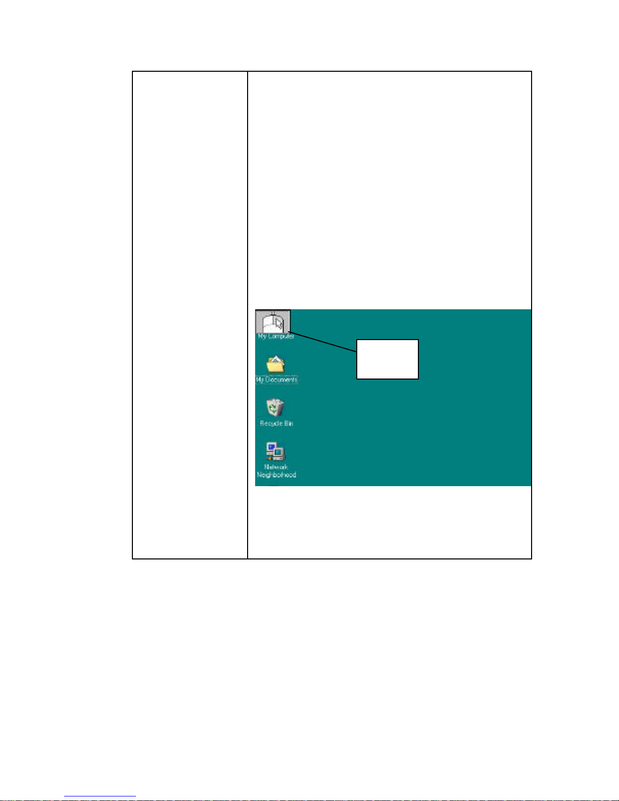
Use the virtual mouse to select the left and right
mouse button functions. The left button is selected
by default.
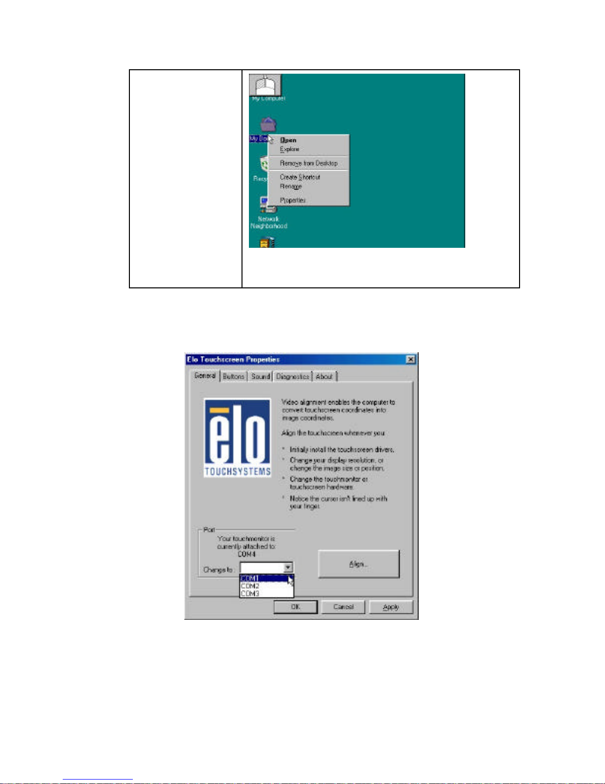
To use the right mouse button function:
1. Enable the right mouse button function from
the icon in the toolbar The virtual mouse
appears on the desktop:
2. Click the virtual mouse’s right button. The
right button is enabled:
3. Click an item on the desktop. The properties
menu appears:
Virtual
mouse
Page 65
55
Note! When you right-click an object, the virtual
mouse goes back to left-button mode.
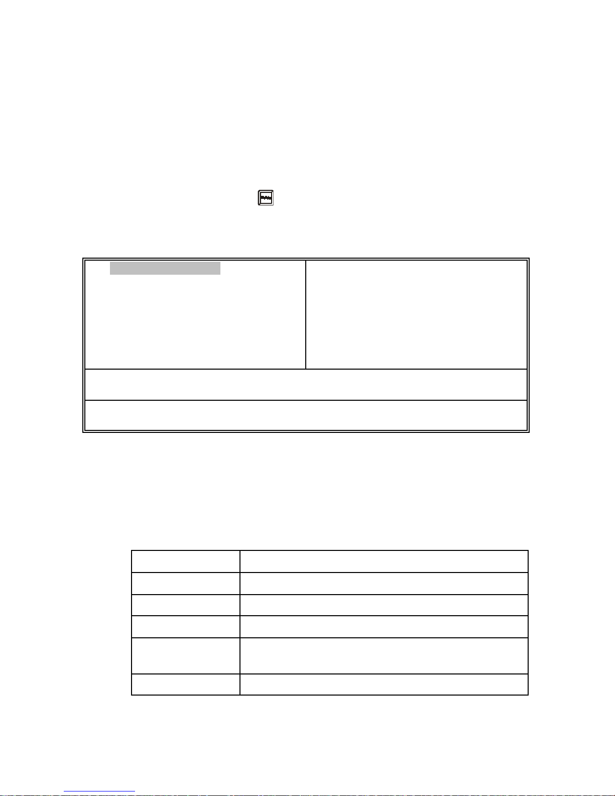
To access advanced features of the Elo Touchscreen, double-click the Elo
Touchscreen icon in the taskbar to open the Elo Touchscreen Properties
dialog box:
Page 66

56
The Elo Touchscreen Properties dialog box enables you to change the
COM 4 port assigned to the Touchscreen, align the cursor, change button
functions, assign sounds to events, and run diagnostics on the
Touchscreen.
This concludes Chapter 4. The next chapter covers the BIOS.
Page 67

CChhaapptteerr 55:: UUssiinngg BBIIOOSS
This chapter describes the BIOS Setup for the PT-4000 POS Stations.
AAbboouutt tthhee SSeettuupp UUttiilliittyy
The computer uses the latest Award BIOS with support for Windows Plug
and Play. The CMOS chip on the mainboard contains the ROM Setup
instructions for configuring the mainboard BIOS.
The BIOS (Basic Input and Output System) Setup Utility displays the
system's configuration status and provides you with optio ns to set system
parameters. The parameters are stored in battery -backed-up CMOS RAM
that saves this information even when the power is turned off. When the
system is turned back on, the system is configured with the values found
in CMOS.
The BIOS Setup Utility enables you to configure:
• Hard drives, diskette drives, and peripherals
• Video display type and display options
• Password protection from unauthorized use
• Power management features
The settings made in the Setup Utility affect how the computer perfo rms.
Before using the Setup Utility, ensure that you understand the Setup
Utility options. Only change settings appropriate for the way you use the
computer.
Note! If you have made settings that you do not want to save, use the "Exit
Without Saving" item and press Y to discard any changes you have
made.
Page 68

58
TThhee SSttaannddaarrdd CCoonnffiigguurraattiioonn
A standard configuration has already been set in the Setup Utility.
However, we recommend that you read this chapter in case you need to
make any changes in the future.
This Setup Utility should be used:
• when changing the system configuration
• when a configuration error is detected and you are prompted to
make changes to the Setup Utility
• when trying to resolve IRQ conflicts
• when making changes to the Power Management configuration
• when changing the password or making other changes to the
Security Setup
Page 69
59
EEnntteerriinngg tthhee SSeettuupp UUttiilliittyy
When you power on the system, BIOS enters the Power -On Self Test (POST)
routines. POST is a series of built-in diagnostics performed by the BIOS.
After the POST routines are completed, the following message appears:
Press DEL to enter SETUP
Pressing the delete key accesses the Award BIOS Setup Utility:
ROM PCI/ISA BIOS (2A69KILG)
CMOS SETUP UTILITY
AWARD SOFTWARE, INC.
STANDARD CMOS SETUP
BIOS FEATURES SETUP
CHIPSET FEATURES SETUP
POWER MANAGEMENT SETUP
PNP/PCI CONFIGURATION
LOAD BIOS DEFAULTS
LOAD SETUP DEFAULTS
INTEGRATED PERIPHERALS
SUPERVISOR PASSWORD
USER PASSWORD
IDE HDD AUTO DETECTION
SAVE & EXIT SETUP
EXIT WITHOUT SAVING
ESC : Quit ↑ ↓ → ← : Select Item
F10 : Save&Exit (Shift)F2 : Change Color
Time, Date, Hard Disk Type…
Figure 18- PT-4000 POS Station BIOS main screen
PT -4000 POS Station BIOS Navigation Keys
The BIOS navigation keys are listed below:
Key Function
←↑↓→
Scrolls through the items on a menu
+/–/PU/PD Modifies the selected field's values
Esc Exits the current menu
F1
Displays a screen that describes all key
functions
F5 Loads previously saved values to CMOS
Page 70
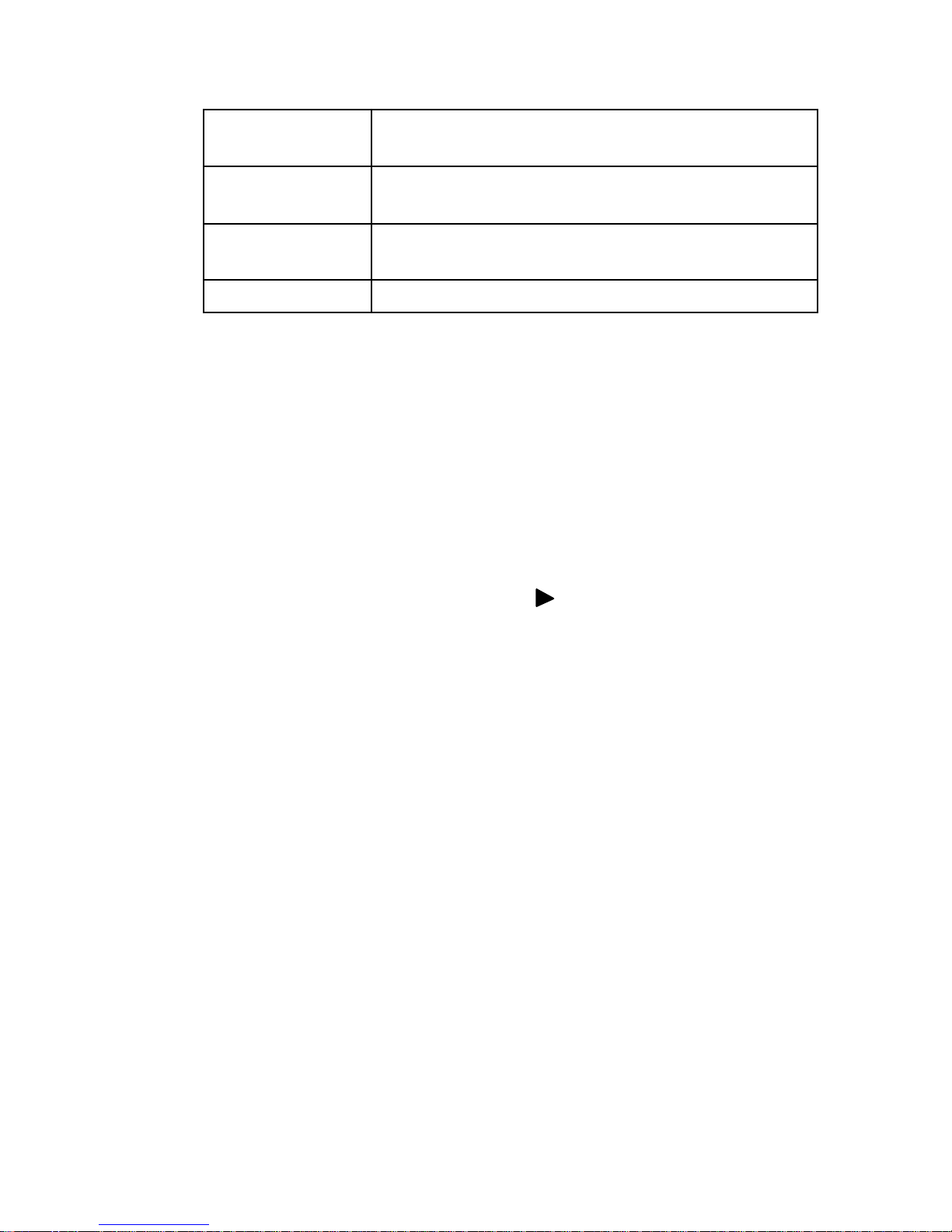
60
F6
Loads a minimum configuration for
troubleshooting.
F7
Loads an optimum setof values for peak
performance
F10
Saves the current configuration and exits
Setup
Shift + F2 Changes the color of the BIOS screen
Using BIOS
When you start the Setup Utility, the main menu appears. The main menu
of the Setup Utility displays a list of the options that are available. A
highlight indicates which option is currently selected. Use the cursor
arrow keys to move the highlight to other options. When an option is
highlighted, execute the option by pressing <Enter>.
Some options lead to pop -up dialog boxes that prompt you to verify that
you wish to execute that option. Other options lead to dialog boxes that
prompt you for information.
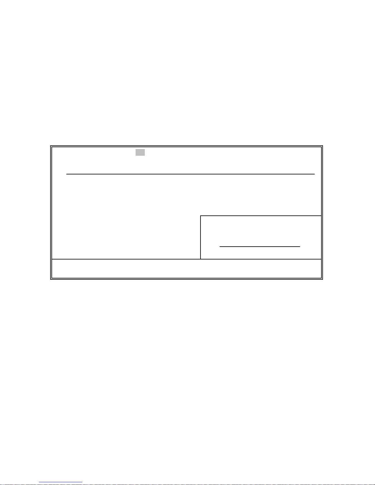
Some options (marked with a triangle ) lead to submenus that enable
you to change the values for the option. Use the cursor arrow keys to
scroll through the items in the submenu.
Page 71
61
TThhee PPTT--44000000 PPOOSS SSttaattiioonn BBIIOOSS
This section describes the BIOS for the PT-4000 POS Station.
SSttaannddaarrdd CCMMOOSS SSeettuupp
This option displays basic information about your system.
ROM PCI/ISA BIOS (2A69KILG)
CMOS SETUP UTILITY
AWARD SOFTWARE, INC.
Date (mm:dd:yy) : Wed, Mar 7 2001
Time (hh:mm:ss) : 1 : 19 : 12
HARD DISKS TYPE SIZE CYLS HEAD PRECOMP LANDZ SECTOR MODE
Primary Master : Auto 0M 0 0 0 0 0 AUTO
Primary Slave : Auto 0M 0 0 0 0 0 AUTO
Secondary Master: Auto 0M 0 0 0 0 0 AUTO
Secondary Master: Auto 0M 0 0 0 0 0 AUTO
Drive A : 1.44M, 3.5 in.
Drive B : None
Video : EGA/VGA
Halt On : All, But Keyboard
Base Memory: 640K
Extended Memory: 64512K
Other Memory: 384K
Total Memory: 65536K
ESC : Quit ↑ ↓ → ← : Select Item PU/PD/+/− : Modify
F10 : Save&Exit (Shift)F2 : Change Color
Date and Time
The Date and Time items show the current date and time on the computer.
If you are running a Windows OS, these items are automatically updated
whenever you make changes to the Windows Date and Time Properties
utility.
Page 72

62
Hard Disks
Your computer has two IDE channels (Primary and Secondary) and each
channel can be installed with one or two devices (Master and Slave). Use
these items to configure each device on the IDE channel.
When configured, the following items are displayed:
• TYPE – displays the type of hard disk drive (HDD) installed.
When set to Auto, indicates that BIOS automatically determines
the hard disk drive’s characteristics.
• SIZE – displays the capacity of the HDD in megabytes (M).
• CYLS – indicates the number of cylinders that the HDD has. A
cylinder is the sum total of all tracks that are in the same location
on every disk surface.
• HEAD – displays the number of heads in the HDD. A head is a
device that reads and writes data on the hard disk.
• PRECOMP – displays the track where precompensation is
initiated. Precompensation is a feature whereby the HDD uses a
stronger magnetic field to write data in sectors that are closer to
the center of the disk. In CAV recording, in which the disk spins
at a constant speed, the sectors closest to the spindle are packed
tighter than the outer sectors.
• LANDZ – displays the location of the safe non-data area on a
hard disk that is used for parking the read/write head.
• SECTOR – displays the number of sectors available on the HDD.
A sector is the smallest unit of storage space on a disk.
• MODE – The MODE option is for IDE hard disk drives only.
MODE has four options Normal, LBA, Large, and Auto.
Note! Set MODE to “NORMAL” for IDE hard disk drives smaller than 528
MB. Set MODE to “LBA” for IDE hard disk drives larger than 528
MB which support Logical Block Addressing mode. Set MODE to
“LARGE” for IDE hard disk drives larger than 528 MB that do not
support LBA mode. The LARGE type of drive is very uncommon and
can only be used under MS-DOS. Currently most IDE hard disk
drives over 528 MB support LBA mode. Set MODE to AUTO to
enable auto detection of your IDE hard disk drive during boot.
Page 73

63
Drive A/Drive B (1.44M, 3.5 in./None)
These items define the characteristics of any diskette drive attached to the
system. You can connect one or two diskette drives.
Video (EGA/VGA)
This item defines the video mode of the system. This mainboard has a
built-in VGA graphics system; you must leave this item at the default
setting.
Halt On (All Errors)
This item defines the operation of the system POST (Power On Self Test)
routine. You can use this item to select which types of errors in the POST
are sufficient to halt the system.
Base Memory, Extended Memory, and Total Memory
These items are automatically detected by the system at start up time.
These are display-only fields. You cannot make changes to these fields.
• Base Memory – This field displays the amount of conventional
memory detected by the system during boot.
• Extended Memory – This field displays the amount of extended
memory detected by the system during boot-up.
• Total Memory – This field displays the total amount of memory
(Base and Extended) detected by the system during boot-up.
Press <Esc> to return to the main screen.
Page 74
64
BBIIOOSS FFeeaattuurreess SSeettuupp
This option displays advanced information about your system.
ROM PCI/ISA BIOS (2A69KILG)
BIOS FEATURES SETUP
AWARD SOFTWARE, INC.
Video BIOS Shadow : Enabled
C8000-CBFFF Shadow : Disabled
CC000-CFFFF Shadow : Disabled
D0000-D3FFF Shadow : Disabled
D4000-D7FFF Shadow : Disabled
D8000-DBFFF Shadow : Disabled
DC000-DFFFF Shadow : Disabled
Virus Warning : Disabled
CPU Internal Cache : Enabled
External Cache : Enabled
CPU L2 Cache ECC Checking : Enabled
Processor Number Feature : Enabled
Quick Power On Self Test : Enabled
Boot From LAN First : Disabled
Boot Sequence : A,C,SCSI
Swap Floppy Drive : Disabled
Boot Up Floppy Seek : Disabled
Boot Up NumLock Status : Off
Gate A20 Option : Fast
Typematic Rate Setting : Disabled
Typematic Rate (Chars/Sec) : 6
Typematic Delay (Msec) : 250
Security Option : Setup
PCI/VGA Palette Snoop : Disabled
PS Select For DRAM > 64MB : Non-OS2
Report No FDD For WIN 95 : No
Esc : Quit ↑ ↓ → ← Select Item
F1 : Help PU/PD/+/- : Modify
F5 : Old Values (Shift) F2 : Color
F6 : Load BIOS Defaults
F7 : Load Setup Defaults
Virus Warning
When enabled, this item provides protection against viruses that try to
write to the boot sector and partition table of your hard disk drive. You
need to disable this item when installing an operating system. We
recommend that you enable anti-virus protection as soon as you have
installed an operating system. The default setting is Disabled.
CPU Internal Cache
All processors that can be installed in this mainboard use internal level 1
(L1) cache memory to improve performance. Leave this item at the
default setting for better performance. The default setting is Enabled.
External Cache
Most processors that can be installed in this system use external level 2
(L2) cache memory to improve performance. Leave this item at the
default setting for better performance. The default setting is Enabled.
Page 75

65
CPU L2 Cache ECC Checking
This item enables or disables ECC (Error Correction Code) error
checking on the CPU cache memory. We recommend that you leave this
item at the default setting. The default setting is Enabled.
Processor Number Feature
Some new processors are installed with a unique processor number. This
number may be used for verification in Internet transactions and ecommerce. If you prefer not to use or distribute the unique processor
number, disable this item to suppress the processor number. The default
setting is Enabled.
Quick Power On Self Test
Enable this item to shorten the power on testing (POST) and have your
system start up faster. You might like to enable this item after you are
confident that your system hardware is operating smoothly. The default
setting is Enabled.
Boot From LAN First
Enable this item to allow the system to boot from the Local Area Network
(LAN). The default setting is Disabled.
Boot Sequence
Use these three items to select the priority and order of the devices that
your system searches for an operating system at start-up time. The default
setting is A, C, SCSI.
Swap Floppy Drive
If you have two floppy diskette drives in your system, this item allows
you to swap the assigned drive letters so that drive A becomes drive B,
and drive B becomes drive A. The default setting is Disabled.
Boot Up Floppy Seek
If this item is enabled, it checks the size of the floppy disk drives at startup time. You don't need to enable this item unless you have a legacy
diskette drive with 360K capacity. The default setting is Enabled.
Page 76

66
Boot Up NumLock Status
This item defines if the keyboard Num Lock key is active when your
system is started. The default setting is On.
Gate A20 Option
This item defines how the system handles legacy software that was
written for an earlier generation of processors. Leave this item at the
default setting. The default setting is Fast.
Typematic Rate Setting
If this item is enabled, you can use the following two items to set the
typematic rate and the typematic delay settings for your keyboard. The
default setting is Disabled.
Typematic Rate (Chars/Sec)
Use this item to define how many characters per second are generated by
a held-down key. The default setting is 6.
Typematic Delay (Msec)
Use this item to define how many milliseconds must elapse before a helddown key begins generating repeat characters. The default setting is 250.
Security Option
If you have installed password protection, this item defines if the
password is required at syste m start up, or if it is only required when a
user tries to enter the Setup Utility. The default setting is Setup.
PCI/VGA Palette Snoop
This item is designed to overcome some problems that can be caused by
some non-standard VGA cards. This board includes a built-in VGA
system that does not require palette snooping so you must leave this item
disabled. The default setting is Disabled.
OS Select For DRAM > 64 MB
This item is only required if you have installed more than 64 MB of
memory and you are running the OS/2 operating system. Otherwise, leave
this item at the default. The default setting is Non-OS2.
Page 77

67
HDD S.M.A.R.T Capability
The S.M.A.R.T. (Self-Monitoring, Analysis, and Reporting Technology)
system is a diagnostics technology that monitors and predicts device
performance. S.M.A.R.T. software resides on both the disk drive and the
host computer. The default setting is Disabled.
The disk drive software monitors the internal performance of the motors,
media, heads, and electronics of the drive. The host software monitors the
overall reliability status of the drive. If a device failure is predicted, the
host software, through the Client WORKS S.M.A.R.T applet, warns the
user of the impending condition and advises appropriate action to protect
the data.
Report No FDD For WIN95 (Yes)
If you are running a system with no floppy drive and using Windows 95,
select Yes for this item to ensure compatibility with the Windows 95 logo
certification. Otherwise, select No. The default setting is Yes.
Video BIOS Shadow
When enabled copies the VGA BIOS into system DRAM for better
performance. The default setting is Disabled.
C8000-CBFFF Shadow to DC000-DFFFF Shadow
When enabled, the ROM with the specified address is copied into system
DRAM, and reduces the amount of memory available to the system. The
default setting is Disabled.
Press <Esc> to return to the main screen.
Page 78
68
CChhiippsseett FFeeaattuurreess SSeettuupp
These options define critical timing parameters of the mainboard. You
should leave the items on this page at their default settings unless you are
very familiar with the technical specifications of your system hardware. If
you change the values incorrectly, you may introduce fatal errors or
recurring instability into your system.
ROM PCI/ISA BIOS (2A69KILG)
CHIPSET FEATURES SETUP
AWARD SOFTWARE, INC.
SDRAM RAS -to-CAS Delay : 3
SDRDAM RAS Precharge Time : 3
SDRAM CAS latency Time : 3
SDRAM Precharge Control : Disabled
DRAM Data Integrity Mode : Non-ECC
System BIOS Cacheable : Enabled
Video BIOS Cacheable : Enabled
Video RAM Cacheable : Enabled
8 Bit I/O Recovery Time : 3
16 Bit I/O Recovery Time : 2
Memory Hole At 15M-16M : Disable
Passive Release : Enabled
Delayed Transaction : Disabled
AGP Aperture Size (MB) : 64
Esc : Quit ↑ ↓ → ← Select Item
F1 : Help PU/PD/+/- : Modify
F5 : Old Values (Shift) F2 : Color
F6 : Load BIOS Defaults
F7 : Load Setup Defaults
SDRAM RAS -to-CAS Delay
This sets the relative delay between the Row Address Strobe (RAS) and the
Column Address Strobe (CAS). Select the RAS-to-CAS delay time in
HCLKs of 2/2 or 3/3. The value is set at the factory depending on the DRAM
installed. Do not change the values in this field unless you have changed the
specifications of the installed DRAM or CPU. The default setting is 3.
SDRAM RAS Precharge Time (3)
DRAM must continually be refreshed or it will lose its data. This option
allows you to determine the number of CPU clocks allocated for the Row
Address Strobe (RAS) to accumulate its charge before the DRAM is
refreshed. If insufficient time is allowed, refresh may be incomplete and
data lost. The default setting is 3.
Page 79

69
SDRAM CAS Latency Time
This item enables you to select the CAS latency time in HCLKs of 2/2 or
3/3. The value is set at the factory depending on the DRAM installed. Do
not change the values in this field unless you change the specifications of
the installed DRAM or the installed CPU. The default setting is 3.
SDRAM Precharge Control
This option sets the number of cycles required for the RAS (Row Address
Strobe) to accumulate a charge before the SDRAM refreshes. Reduce the
precharge time to 2 to improve SDRAM performance. The default setting
is Disabled.
Note! If a precharge time setting of 2 is insufficient for the installed
SDRAM, the SDRAM may not be refreshed properly and may fail to
store data. Set the precharge time to 3 if the system becomes unstable.
DRAM Data Integrity Mode
Set this to ECC (error-correcting code) or Non-ECC according to the type
of installed DRAM. The default setting is Non-ECC.
System BIOS/Video RAM Cacheable
These items allow the video and system to be cached in memory for faster
execution. Leave these items at the default setting for better performance.
The default setting is Enabled.
8-Bit I/O Recovery Time
This item allows you to determine the recovery time allowed for 8-bit I/O.
The recovery time is the length of time (measured in CPU clocks) in
which the system delays after the completion of an input/output request.
This delay occurs because the CPU is operating so much faster than the
input/output bus that the CPU must be delayed to allow for the
completion of the I/O. Options are NA and 1 ~ 8. The default setting is 3.
16-Bit I/O Recovery Time
This item allows you to determine the recovery time allowed for 16-bit
I/O. Options are NA and 1 ~ 4. The default setting is 2.
Page 80

70
Memory Hole At 15M –16M
This item is used to reserve memory space for ISA expansion cards that
require it. The default setting is Disabled.
Passive Release
When enabled the CPU to PCI bus access is allowed during passive
release. Otherwise, only the PCI master access to local DRAM is
permitted. The default setting is Disabled.
Delayed Transaction
If the chipset has an embedded 32-bit write buffer, to support delay
transaction cycles, you can enable this item to provide compliance with
PCI Ver. 2.1 specifications. We recommend that you leave this item at the
default setting. The default setting is Enabled.
AGP Aperture Size
This item defines the size of the aperture if you use an AGP graphics
adapter. The AGP aperture refers to a section of the PCI memory address
range used for graphics memory. We recommend that you leave this item
at the default setting. The default setting is 64.
Press <Esc> to return to the main screen.
PPoowweerr MMaannaaggeemmeenntt SSeettuupp OOppttiioonn
This option enables you to control the system power management. This
mainboard supports ACPI (Advanced Configuration and Power Interface).
The system has various power saving modes including powering down
the hard disk, turning off the video, suspending to RAM, and software
power down that allows the system to be automatically resumed by
certain events.
The power-saving modes can be controlled by timeouts. If the system is
inactive for a time, the timeouts begin counting. If the inactivity continues
so that the timeout period elapses, the system enters a power-saving mode.
If any item in the list of Reload Global Timer Events is Enabled, then any
activity on that item will reset the timeout counters to zero.
Page 81
71
If the system is suspended or has been powered down by software, it can be
resumed by a wake up call that is generated by incoming traffic to a modem,
a LAN card, a PCI card, or a fixed alarm on the system realtime clock.
ROM PCI/ISA BIOS (2A69KILG)
POWER MANAGEMENT SETUP
AWARD SOFTWARE, INC.
** Reload Global Timer Events**
IRQ[3-7,9-15],NMI : Disabled
Primary IDE 0 : Disabled
Primary IDE 1 : Disabled
Secondary IDE 0 : Disabled
Secondary IDE 1 : Disabled
Floppy Disk : Disabled
Serial Port : Enabled
Parallel Port : Disabled
Power Management : User Define
PM Control by APM : Yes
Video Off Method : V/H SYNC+BLANK
Video Off After : NA
Doze Mode : Disable
Standby Mode : Disable
Suspend Mode : Disable
HDD Power Down : Disable
PCI/VGA Act-Monitor : Disabled
IRQ 8 Break Suspend : Disabled
Esc : Quit ↑ ↓ → ← Select Item
F1 : Help PU/PD/+/- : Modify
F5 : Old Values (Shift) F2 : Color
F6 : Load BIOS Defaults
F7 : Load Setup Defaults
Power Management
This item acts like a master switch for the power-saving modes and hard
disk timeouts. If this item is set to Max Sav ing, power-saving modes
occur after a short timeout. If this item is set to Min Saving, power-saving
modes occur after a longer timeout. If the item is set to User Define, you
can insert your own timeouts for the power-saving modes. The default
setting is User Define.
PM Control by APM
If you enable this item, it allows operating systems, such as Win 98/95 that
have APM (Advanced Power Management) to assume control over some of
the power management operations on your system. The default setting is No.
Video Off Method
This item defines how the video is powered down to save power. This
item is set to DPMS (Display Power Management Software) by default.
The default setting is V/H SYNC+BLANK.
Page 82

72
Video Off After
This option defines if the video is powered down when the system is put
into suspend mode. The default setting is N/A.
Doze Mode
The system speed will change from turbo to slow if no Power
Management events occur for a specified length of time. Full power
function will return when a Power Management event is detected. The
default setting is Disabled.
Standby Mode
When enabled and after the set time of system inactivity, the fixed disk
drive and the video would be shut off while all other devices still operate
at full speed. The default setting is Disabled.
Suspend Mode
The CPU clock will be stopped and the video signal will be suspended if
no Power Management events occur for a specified length of time. Full
power function will return when a Power Management event is detected.
Options are from 1 Min to 1 Hour and disabled. The default setting is
Disabled.
HDD Power Down
The IDE hard drive will spin down if it is not accessed within a specified
length of time. Options are from 1 Min to 15 Min and disabled. The
default setting is Disabled.
PCI/VGA Act-Monitor
When enabled, any video activity restarts the global timer for Standby
mode. The default setting is Disabled.
IRQ 8 Break Suspend
This field allows you to enable or disable monitoring of IRQ 8 so that it
does not awaken the system from Suspend mode. The default setting is
Disabled.
Page 83

73
** Reload Global Timer Events **
Global Timer (power management) events are I/O events whose
occurrence can prevent the system from entering a power saving mode or
can awaken the system from such a mode. In effect, the system remains
alert for anything that occurs to a device that is configured as Enabled,
even when the system is in a power-down mode.
IRQ[3-7, 9-15], NMI
When enabled, any event occurring at IRQs 3 through 15 (excluding IRQ
8) turns on a system which has been powered down. The default setting is
Disabled.
Primary/Secondary IDE 1/0
When these items are enabled, the system will restart the power-saving
timeout counters when any activity is detected on any of the drives or
devices on the primary or secondary IDE channels. The default setting is
Disabled.
Floppy Disk, Serial Port, Parallel Port
When these items are enabled, the system will restart the power-saving
timeout counters when any activity is detected on the floppy disk drive,
serial ports, or the parallel port. The default setting is Disabled.
Press <Esc> to return to the main screen.
Page 84
74
PPNNPP//PPCCII CCoonnffiigguurraattiioonn OOppttiioonn
These options configure how PnP (Plug and Play) and PCI expansion
cards operate in your system. Both the ISA and PCI buses on the
mainboard use system IRQs (Interrupt ReQuests) and DMAs (Direct
Memory Access). You must set the IRQ and DMA assignments correctly
through the PnP/PCI Configurations Setup utility; otherwise, the
mainboard will not work properly. Selecting PnP/PCI Configurations on
the main program screen displays this menu:
ROM PCI/ISA BIOS (2A69KILG)
PNP/PCI CONFIGURATION
AWARD SOFTWARE, INC.
Used MEM base addr : N/A PNP OS Installed : No
Resources Controlled By : Manual
Reset Configuration Data : Disabled
IRQ-3 assigned to : Legacy ISA
IRQ-4 assigned to : Legacy ISA
IRQ-5 assigned to : Legacy ISA
IRQ-7 assigned to : Legacy ISA
IRQ-9 assigned to : PCI/ISA PnP
IRQ-10 assigned to : Legacy ISA
IRQ-11 assigned to : PCI/ISA PnP
IRQ-12 assigned to : PCI/ISA PnP
IRQ-14 assigned to : PCI/ISA PnP
IRQ-15 assigned to : PCI/ISA PnP
DMA-0 assigned to : PCI/ISA PnP
DMA-1 assigned to : PCI/ISA PnP
DMA-3 assigned to : PCI/ISA PnP
DMA-5 assigned to : PCI/ISA PnP
DMA-6 assigned to : PCI/ISA PnP
DMA-7 assigned to : PCI/ISA PnP
Esc : Quit ↑ ↓ → ← Select Item
F1 : Help PU/PD/+/- : Modify
F5 : Old Values (Shift) F2 : Color
F6 : Load BIOS Defaults
F7 : Load Setup Defaults
PNP OS Installed
Setting this option to “Yes” allows the PnP OS (instead of BIOS) to
assign the system resources such as IRQ and I/O address to the ISA PnP
device. The default setting is No.
Resources Controlled By
You should leave this item at the default Auto(ESCD). Under this setting,
the system dynamically allocates resources to plug and play devices as
they are required.
Page 85

75
If you cannot get a legacy ISA (Industry Standard Architecture) expansion
card to work properly, you might be able to solve the problem by
changing this item to Manual, which displays the IRQ Resources and
Memory Resources list.
In the IRQ Resources list, if you change any of the IRQ assignations to
Legacy ISA, then that Interrupt Request Line is reserved for a legacy ISA
expansion card.
In the Memory Resources list, use the first item Reserved Memory Base
to set the start address of the memory you want to reserve for the ISA
expansion card. Use the second item Reserved Memory Length to set the
amount of reserved memory.
Reset Configuration Data
If you enable this item and restart the system, any Plug and Play
configuration data stored in the BIOS Setup is cleared from memory. New
updated data is created. The default setting is Disabled.
Press <Esc> to return to the main screen.
Page 86
76
IInntteeggrraatteedd PPeerriipphheerraallss OOppttiioonn
This option displays a list of items that defines the operation of peripheral
components on the system's input/output ports.
ROM PCI/ISA BIOS (2A69KILG)
INTEGRATED PERIPHERALS
AWARD SOFTWARE, INC.
UART Mode Select : ASKIR
UART2 Duplex Mode : Half
RxD , TxD Active : Hi,Lo
IR Transmission Delay : Enabled
Onboard Parallel Port : 378
Onboard Parallel Port IRQ : 7
Parallel Port Mode : ECP+EPP
ECP Mode Use DMA : 3
EPP Mode Select : EPP1.7
Onboard Serial Port 3 : 3E8H
Serial Port 3 Use IRQ : IRQ10
Onboard Serial Port 4 : 2E8H
Serial Port 4 Use IRQ : IRQ7
IDD HDD Block Mode : Enabled
IDE Primary Master PIO : Auto
IDE Primary Slave PIO : Auto
IDE Secondary Master PIO : Auto
IDE Secondary Slave PIO : Auto
IDE Primary Master UDMA : Auto
IDE Primary Slave UDMA : Auto
IDE Secondary Master UDMA : Auto
IDE Secondary Slave UDMA : Auto
On-Chip Primary PCI IDE : Enabled
On-Chip Secondary PCI IDE : Enabled
USB Keyboard Support : Enabled
Onboard FDC Controller : Enabled
Onboard Serial Port 1 : 3F8
Onboard Serial Port 1 IRQ : 4
Onboard Serial Port 2 : 2F8
Onboard Serial Port 2 IRQ : 3
Esc : Quit ↑ ↓ → ← Select Item
F1 : Help PU/PD/+/- : Modify
F5 : Old Values (Shift) F2 : Color
F6 : Load BIOS Defaults
F7 : Load Setup Defaults
IDE HDD Block Mode
Enable this field if your IDE hard drive supports block mode. Block mode
enables BIOS to automatically detect the optimal number of block read
and writes per sector that the drive can support and improves the speed of
access to IDE devices. The default setting is Enabled.
IDE Primary/Secondary Master/Slave PIO
Each IDE channel supports a master device and a slave device. These four
items let you assign which kind of PIO (Programmed Input/Output) is
used by IDE devices. Choose Auto to let the system auto detect which
PIO mode is best, or select a PIO mode from 0-4. The default setting is
Auto.
Page 87

77
IDE Primary/Secondary Master/Slave UDMA
Each IDE channel supports a master device and a slave device. This
mainboard supports UltraDMA technology, which provides faster access
to IDE devices. The default setting is Auto.
If you install a device that supports UltraDMA, change the appropriate
item on this list to Auto. You may have to install the UltraDMA driver
supplied with this mainboard in order to use an UltraDMA device.
On-Chip IDE Primary/Secondary PCI IDE
Use these items to enable or disable the PCI IDE channels that are
integrated on the mainboard. The default setting is Enabled.
USB Keyboard Support
Enable this item if you plan to use a keyboard connected through the USB
port in a legacy operating system (such as DOS) that does not support
Plug and Play. The default setting is Disabled.
Onboard FDC Controller
This option enables the onboard floppy disk drive controller. The default
setting is Enabled.
Onboard Serial Port 1
This option is used to assign the I/O address for onboard serial port 1
(COM1). The default setting is 3F8.
Onboard Serial Port 1 IRQ
This option is used to assign the interrupt request (IRQ) for onboard serial
port 1 (COM1). The default setting is 4.
Onboard Serial Port 2
This option is used to assign the I/O address for onboard serial port 2
(COM2). The default setting is 2F8.
Onboard Serial Port 2 IRQ
This option is used to assign the interrupt request (IRQ) for onboard serial
port 2 (COM2). The default setting is 3.
Page 88

78
UART Mode Select
This field is available if the Onboard Serial Port 2 field is set to any
option but Disabled. UART Mode Select enables you to select the
infrared communication protocol-Normal (default), IrDA, or ASKIR.
IrDA is an infrared communication protocol with a maximum baud rate
up to 115.2K bps. ASKIR is Sharp's infrared communication protocol
with a maximum baud rate up to 57.6K bps. The default setting is Normal.
UR2 Duplex Mode
This field is available when UART 2 Mode is set to either ASKIR or
IrDA. This item enables you to determine the infrared (IR) function of the
onboard infrared chip. The default setting is Half.
Full-duplex means that you can transmit and send information
simultaneously. Half-duplex is the transmission of data in both directions,
but only one direction at a time.
RD, TxD Acti ve
Defines the voltage level for Infrared module RxD (receive) mode and
TxD (transmit) mode. This setting has to match the requirements of the
infrared module used in the system. The default setting is Hi, Lo.
IR Transmission Delay
When enabled, utilizes the capability of the mainboard to allow faster
infrared transmission rates. The default setting is Enabled.
Onboard Parallel Port
This option is used to assign the I/O address for the onboard parallel port.
The default setting is 378.
Onboard Parallel Port IRQ
This option is used to assign the interrupt request (IRQ) for the onboard
parallel port. The default setting is 7.
Parallel Port Mode
Enables you to set the data transfer protocol for your parallel port. There
are four options: SPP (Standard Paralle l Port), EPP (Enhanced Parallel
Port), ECP (Extended Capabilities Port), and ECP+EPP. The default
setting is ECP+EPP.
Page 89

79
SPP allows data output only. Extended Capabilities Port (ECP) and Enhanced
Parallel Port (EPP) are bi-directional modes, allowing both data input and
output. ECP and EPP modes are only supported with EPP and ECP aware
peripherals.
ECP Mode Use DMA
When the onboard parallel port is set to ECP mode, the parallel port can
use DMA 3 or DMA 1. The default setting is 3.
EPP Mode Select
Sets the EP P specification. There are two options— EPP1.9 and EPP1.7.
The default setting is EPP1.7.
Onboard Serial Port 3
This option is used to assign the I/O address for onboard serial port 3
(COM3), which is used for the rear customer display. The default setting
is 3E8H.
Serial Port 3 Use IRQ
This option is used to assign the interrupt request (IRQ) for onboard serial
port 3 (COM3). The default setting is IRQ 10.
Onboard Serial Port 4
This option is used to assign the I/O address for onboard serial port 4
(COM4), which is used for the Touchscreen. The default setting is 2E8H.
Serial Port 4 Use IRQ
This option is used to assign the interrupt request (IRQ) for onboard serial
port 4 (COM4). The default setting is IRQ 7.
Press <Esc> to return to the main screen.
Page 90
80
OOtthheerr BBIIOOSS OOppttiioonnss
This section covers the other options that are available from the main
screen:
ROM PCI/ISA BIOS (2A69KILG)
CMOS SETUP UTILITY
AWARD SOFTWARE, INC.
STANDARD CMOS SETUP
BIOS FEATURES SETUP
CHIPSET FEATURES SETUP
POWER MANAGEMENT SETUP
PNP/PCI CONFIGURATION
LOAD BIOS DEFAULTS
LOAD SETUP DEFAULTS
INTEGRATED PERIPHERALS
SUPERVISOR PASSWORD
USER PASSWORD
IDE HDD AUTO DETECTION
SAVE & EXIT SETUP
EXIT WITHOUT SAVING
ESC : Quit ↑ ↓ → ← : Select Item
F10 : Save&Exit (Shift)F2 : Change Color
Time, Date, Hard Disk Type…
IIDDEE HHDDDD AAuuttoo DDeetteeccttiioonn OOppttiioonn
If your system has an IDE hard drive, you can use this utility to detect its
parameters and enter them into the Standard CMOS Setup automatically.
Scroll to IDE Auto Detection and press <Enter> to begin IDE drive
detection. If the auto-detected parameters displayed do not match the ones
that should be used for your hard drive, do not accept them. Press the
<N> key to reject the values and enter the correct ones manually in the
Standard CMOS Setup screen.
Note! If you are setting up a new hard disk drive that supports LBA mode,
more than one line will appear in the parameter box. Choose the line
that lists LBA for an LBA drive.
Do not choose “Large” or “Normal” if the hard disk drive is already fully
formatted when you installed it. Select the mode that was used to format it.
Page 91

81
LLooaadd BBIIOOSS DDeeffaauullttss OOppttiioonn
This option opens a dialog box that lets you load fail-safe defaults for all
appropriate items in the Setup Utility.
Follow these instructions:
1. From the ma in screen, scroll to Load BIOS Defaults.
2. Press <Enter> to open the Load BIOS Defaults screen.
3. Press <Y>.
4. Press <Enter> to load the defaults.
The fail-safe defaults place no great demands on the system and are
generally stable. If your system is not functioning correctly, try loading
the fail-safe defaults as a first step in getting your system working
properly again. If you only want to load fail-safe defaults for a specific
option, select and display that option, and then press <F6>.
LLooaadd SSeettuupp DDeeffaauullttss OOppttiioonn
This option opens a dialog box that lets you load optimized defaults for
all appropriate items in the Setup Utility.
Follow these instructions:
1. From the main screen, scroll to Load Setup Defaults.
2. Press <Enter> to open the Load Setup Defaults screen.
3. Press <Y>.
4. Press <Enter> to load the defaults.
The optimized defaults place demands on the system that may be greater
than the performance level of the components, such as the CPU and the
memory. You can cause fatal errors or instability if you load the optimized
defaults when your hardware does not support them. If you only want to
load Setup defaults for a specific option, select and display that option,
and then press <F7>.
Page 92
82
SSeett SSuuppeerrvviissoorr aanndd UUsseerr PPaasssswwoorrddss OOppttiioonnss
These items can be used to install a password. A Supervisor password
takes precedence over a User password, and the Supervisor can limit the
activities of a User. To install a password, follow these steps:
1. Highlight the item Set Supervisor/User Password on the main
menu and press <Enter>.
2. The password dialog box appears.
Enter Password:
3. If you are installing a new password, type in the password. You
cannot use more than eight characters or numbers. The Set
Supervisor/User Password item differentiates between upper and
lower case characters. Press <Enter> after you have typed in the
password. If you are deleting a password that is already installed
press <Enter> when the password dialog box appears. You see a
message that indicates that the password has been disabled.
PASSWORD DISABLED !!!
Press any key to continue . . .
4. Press any key. You are prompted to confirm the password.
Confirm Password:
5. Type the password again and press <Enter>, or press <Enter> if
you are deleting a password that is already installed.
Write the passwords down and keep them in a safe place. Note that if you
do not save your changes when you exit BIOS, changes to the passwords
will be saved anyway.
Page 93

83
SSaavvee && EExxiitt SSeettuupp OOppttiioonn
Highlight this item and press <Enter> to save the changes that you have
made in the Setup Utility and exit the Setup Utility. When the Save and
Exit dialog box appears, press <Y> to save and exit, or press <N> to
return to the main menu:
EExxiitt WWiitthhoouutt SSaavviinngg
Highlight this item and press <Enter> to discard any changes that you
have made in the Setup Utility and exit the Setup Utility. When the Exit
Without Saving dialog box appears, press <Y> to discard changes and
exit, or press <N> to return to the main menu.
Note! If you have made settings that you do not want to save, use the "Exit
Without Saving" item and press Y to discard any changes you have
made.
Page 94

84
AAppppeennddiixx AA:: SSppeecciiffiiccaattiioonnss
PPTT--44000000 LLCCDD PPOOSS TTeerrmmiinnaall SSppeecciiffiiccaattiioonnss
• Intel Celeron 300~600 MHz+, P III 500~750 MHz+
• 64 MB Memory, expandable to 512 MB
• DiskOnChip expandable to 288 MB, share with SSD (optional)
• 3.5-inch IDE hard drive or 2.5-inch IDE hard drive (optional)
• 12.1/13.3-inch LCD panel, color, TFT (Optional for DSTN)
• Touchscreen (resistive or capacitive)
• I/O Interfaces:
– 4 RS232 ports, 3 external with D9 pin connector with
+5VDC & +12VDC
– 1 parallel port
– 1 Ethernet, 10/100 BASE-T
– 1 PS/2 keyboard port
– 1 PS/2 mouse port
– 1 XVGA (CRT support up to 1024x768)
– 1 Cash Drawer port (24VDC – supports two cash drawers)
– 2 USB ports
– Stereo audio out jack
• Options:
– Magnetic card reader, single/dual/three tracks
– Barcode card reader
– Customer pole display/rear customer display
– PCMCIA or fax/modem
– Internal floppy drive or CD-ROM
– Internal Smart Card Reader
– RF (Radio Frequency) reader
– CCD (Consumer Computing Device)
– Hard disk drive
– Infrared keyboard
Page 95

85
• Support DOS, Windows ME/2000/98/95/NT
• Safety & EMI: US, CUL, FCC, CE, VCCI Class A
• Dimensions: W x D x H: 12.8 x 13.4 x 12.4 (inch)
(325 mm x 340 mm x 315 mm)
(Packing Size: 18.3 x 23.2 x 16.3 (inch))
• Net weight: 7.2 kg, Gross weight :12.8 kg
Page 96

AAppppeennddiixx BB:: TTrroouubblleesshhoooottiinngg
This appendix describes locating and solving problems that you may
encounter while using your computer.
LLooccaattiinngg aa PPrroobblleemm
Problems with your computer can be caused by something as minor as an
unplugged power cord— or as major as a damaged hard disk. The
information in this appendix is designed to help you find and solve minor
problems. If you try all the suggested solutions and you still have a
problem, make a list of what steps you have taken to correct the problem
and contact your dealer.
The problems that you will encounter can be divided into two basic
categories: hardware problems and software problems. Hardware
problems can be further divided into electrical and mechanical problems.
You will know you have a hardware problem if the screen is dark, the
computer cannot read the disk drives, or you get an error message during
the Power-On Self Test (POST).
Software errors can occur at several levels. The ROM BIOS and the
operating system can give error messages. On top of this, each application
software package has its own set of error messages. It is important to
determine whether the software error message you are getting is from the
application or the operating system. Once you know this, you can look in
the respective manual for a solution to the problem.
Page 97

87
CChheecckkiinngg CCaabblleess aanndd CCoonnnneeccttiioonnss
To check the power cables, and connections:
• Check the power outlet, the power cord, and any power switches
that may affect your computer. Check the wall outlet or power
strip with an item that you know is functioning properly (a lamp
or radio is a convenient item for checking the power). You may
also need to check the fuses and breakers in your electric box. If
the outlet is controlled by a wall switch, make sure that the switch
is on. If your computer is plugged into a power strip with an
on/off switch, make sure the switch is on.
• With the computer’s power switched off, check all cable
connections. If the computer is connected to any peripheral
devices, look for loose or disconnected cables. If the computer is
too close to a wall, a cable connection may be loose or the cables
may be crimped.
Warning! Do not substitute cables for different devices (other than
the manufacturer recommended cables) even if they look
exactly alike. The wiring inside the cable may be different.
When you are certain that you have power available and all connections
are good, turn the computer on again. If the computer still does not start,
you may have a hardware problem.
TThhee PPoowweerr--OOnn SSeellff TTeesstt
The Power-On Self Test (POST) runs every time you turn on or reset the
computer. The POST checks memory, the mainboard, the display, the
keyboard, the disk drives, and other installed options.
A few seconds after you turn on your computer, a copyright message
appears on your display screen. A memory test message appears next; as
the test continues, memory size increases until all installed memory is
tested. Normally, the only test routine visible on the screen will be the
memory test.
Page 98

88
If failure is detected in an area other than the mainboard (such as the
keyboard or an adapter card), an error message is displayed on the screen
and testing is stopped.
If your system does not successfully complete the POST, but displays a
blank screen, emits a series of beeps, or displays an error code, consult
your dealer.
GGeenneerraall HHaarrddwwaarree PPrroobblleemmss
A few common hardware problems and suggested solutions are presented
in the table below:
Problem Solution
The display screen is dark. Adjust the screen brightness. (Refer to
page 42).
Make sure that the computer is not in
Suspend mode.
An incorrect date and time are
displayed.
Correct the date and time using the
DOS DATE and TIME commands or
the options in the Setup Utility. (You
can also set the date and time in
Windows by double click ing the clock
on the task bar or in the control panel.)
If the date and time become incorrect
after a short time, your CMOS battery
may be depleted. Contact your dealer
to change the battery.
The message:
“Invalid system disk,
Replace the disk, and then press
any key”
appears during boot.
Check and make sure that you do not
have a non-bootable floppy diskette
inserted in your floppy drive. If your
FDD is empty, you may not have an
operating system installed on your
drive. Contact your dealer for support.
You hear irregular beeps during
operation of the computer and the
system halts.
The problem is beyond the scope of
this manual. Contact your dealer for
support.
Page 99

89
Problem Solution
An unidentified message is di splayed. Reboot the computer and run the
BIOS Setup Utility. Confirm the Setup
Utility parameters. If the same
message is displayed after booting up
again, contact your dealer for support.
The system cannot access the CDROM/DVD-ROM drive.
Check that a CD/DVD is properly
inserted in the drive.
You cannot operate the printer. Check the printer cable connection.
Ensure that the printer power switch is
turned on.
Confirm that the printer is on-line.
You can’t save data to disk. Ensure that the disk has been
formatted. Consult your operating
system man ual for information on
formatting floppy diskettes.
The diskette is write-protected. Eject
the diskette, remove the write
protection, and try again.
The diskette if full. Try using another
diskette or free up some space on the
diskette.
The disk drive is not operating. contact
your dealer for support.
You cannot use the mouse. Check the cable connection.
Check the mouse with another
application to see if there is a software
incompatibility problem.
Check the mouse with another
computer to see if it works. If it doesn’t
operate on a different system, replace
the mouse.
CCoonnttaaccttiinngg YYoouurr DDeeaalleerr
If you still have a problem after reading the preceding sections, contact
your dealer.
Page 100
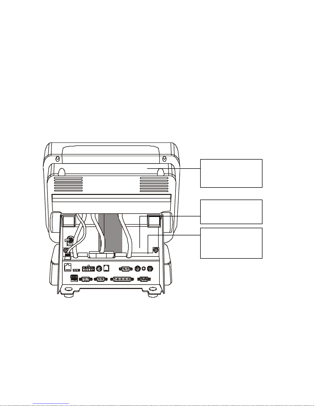
AAppppeennddiixx CC:: JJuummppeerr SSeettttiinnggss
This appendix provides information on jumper settings on the PT-4000
POS Station.
PPTT--44000000 PPOOSS SSttaattiioonn PPCCBB JJuummppeerr SSeettttiinnggss
Location of PCB Boards
The following illustration shows the location of the PCB boards. The rear
cover is removed. Refer to page 14 for instructions on remo ving the rear
cover:
Figure 19 – Location of PCB boards
MSR PCB
(inside LCD panel
unit)
Power PCB
(behind I/O ports)
Base VGA PCB
(behind I/O ports –
under Power PCB)
 Loading...