

Page 1
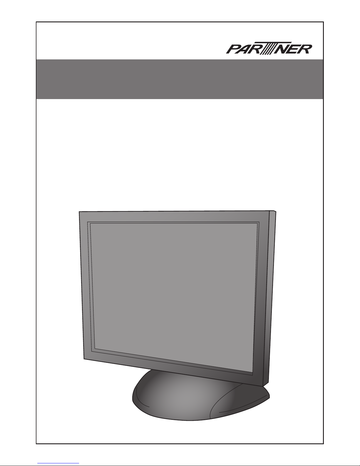
LCD Monitor
PM-15
User Manual
Page 2

Page 3

i
TABLE OF CONTENTS
1 GENERAL OVERVIEW �������������������������������������������������������������� 1
1�1 Flat Panel Display �����������������������������������������������������������������������������������1
1�2 Touchscreen ���������������������������������������������������������������������������������������������1
1�3 Mounting Options �������������������������������������������������������������������������������������1
1�4 Modular Magnetic Card Reader ���������������������������������������������������������������1
2 Contents of packing �������������������������������������������������������������������� 2
3 Installation of the PM15 Monitor ������������������������������������������������� 2
3�1 Cable Installation��������������������������������������������������������������������������������������2
4 Operating the monitor ����������������������������������������������������������������� 3
4�1 Auto Adjusting ������������������������������������������������������������������������������������������3
5 Using the On Screen Display (OSD) ������������������������������������������ 4
5�1 OSD Function�������������������������������������������������������������������������������������������4
5�2 Contrast����������������������������������������������������������������������������������������������������5
5�3 Brightness ������������������������������������������������������������������������������������������������5
5�4 Color Adjust ����������������������������������������������������������������������������������������������5
5�5 Color Temp �����������������������������������������������������������������������������������������������6
5�6 Clock ��������������������������������������������������������������������������������������������������������6
5�7 Phase �������������������������������������������������������������������������������������������������������6
5�8 Gamma ����������������������������������������������������������������������������������������������������6
5�9 Sharpness ������������������������������������������������������������������������������������������������7
5�10 H�Position �����������������������������������������������������������������������������������������������7
5�11 V�Position������������������������������������������������������������������������������������������������7
5�12 OSD H�Pos���������������������������������������������������������������������������������������������8
5�13 OSD V�Pos� ��������������������������������������������������������������������������������������������8
5�14 OSD Timer ���������������������������������������������������������������������������������������������8
5�15 Language �����������������������������������������������������������������������������������������������8
5�16 Reset ������������������������������������������������������������������������������������������������������9
5�17 Volume ���������������������������������������������������������������������������������������������������9
6 Driver Installation ������������������������������������������������������������������������ 9
6�1 Touchscreen ���������������������������������������������������������������������������������������������9
6�2 Calibrating the touchscreen �������������������������������������������������������������������13
Page 4

ii
7 Maintenance and Care ������������������������������������������������������������� 14
8 General Points �������������������������������������������������������������������������� 15
9 Troubleshooting ������������������������������������������������������������������������ 15
9�1 Additional help ����������������������������������������������������������������������������������������15
10 Technical Data ������������������������������������������������������������������������ 16
10.1 Product Specication ���������������������������������������������������������������������������16
11 Safety Instructions ������������������������������������������������������������������ 17
12 Further Notices ����������������������������������������������������������������������� 17
13 Warranty ��������������������������������������������������������������������������������� 17
14 Statement of Conrmation ������������������������������������������������������ 17
15 FCC Warning Statement �������������������������������������������������������� 18
Page 5
1
GENERAL OVERVIEW
1
Partner Tech is proud to offer the PM15 LCD monitor. It offers a versatile solution for many types of
applications. Options include a resistive touchscreen, magnetic card reader as well as many types of
exible mounting solutions.
Flat Panel Display 1.1
This at panel display features an active matrix TFT LCD screen. It provides crisp, bright, color images
with a maximum resolution of 1024x768 producing a full screen image from edge to edge. The 15”
display has a wide viewing angle of up to 70 degrees and a brightness of approximately 250 cd/m2
(without touch) or “NITS”. The display easily interfaces with your PC via direct VGA input just as any
monitor would connect. It includes a desktop stand, has an optional wall mount bracket, and is available
with an Ivory or Black housing.
Touchscreen1.2
The PM15 uses a touch screen by Touch screen technology. It was designed with the harshest
environments in mind, so it’s no wonder that it excels in reliability, durability, and expected product
life. Impervious to environmental conditions such as liquid spills and splashes, humidity, these screens
are the most contamination resistant available.
Touch screen technology is the workhorse of resistive touchscreens, providing unsurpassed
performance in POS, industrial, medical, and transportation applications. Touch the screen with a
nger, gloved hand, ngernail, or object such as a credit card, and you’ll receive a fast, accurate
response every time.
Software drivers are included which allow the screen to work with any mouse driven PC application in
DOS, Windows or Linux* environments.
(*Drivers for Linux are not included, but are supported)
IMPORTANT
The Touch Monitor can thus take over the function of both
monitor and mouse, although a normal mouse can still be
used in parallel to the Touch Monitor.
Mounting Options1.3
The PM15 comes standard with a desktop base or with an optional bracket using the VESA standard for
other versatile mounting congurations such as wall or pole mounting.
Modular Magnetic Card Reader1.4
The PM15 also provides an integrated interface for a magnetic card reader which conforms to the
ANSI, ISO, JIS, AAMVA and CDL standards.
Page 6
2
Contents of packing
2
Prior to taking into operation your PM15 monitor, please check whether the following parts are
included and undamaged:
1 CD with touchscreen driver
1 Adaptor
Installation of the PM15 Monitor
3
The following steps are necessary for the device to function properly:
Switch the computer OFF.
1.
Connect the PM15 monitor to the computer. (For best results, set the computers screen resolution to 2.
1024x768).
Switch your computer and the monitor back ON.
3.
Adjust the display for the graphic card in the computer by means of the On Screen Display (OSD) 4.
Auto Adjusting feature. This step is important for getting the best picture quality. (section 4.1)
(Touchscreen Monitor Only) Install the touchscreen drivers for the corresponding operating system
5.
(chapter 6).
NOTE
The PM15 must be used with the power adaptor provided.
Cable Installation3.1
The installation of the cables must be done with the computer switched off. Begin by connecting the
VGA cable, the RS232 or USB cable, audio cable then the power cable.
Once connected, turn the PM15 monitor ON. After about 3 seconds, you should see the LED on the
front panel light up green followed by an image on the screen.
IMPORTANT
If the computer is in suspend or standby mode the LED will
be red. If the SVGA cable between the Monitor and computer
is disconnected, the LED lights up red.
1 PM15 Monitor
Page 7
3
Operating the monitor
4
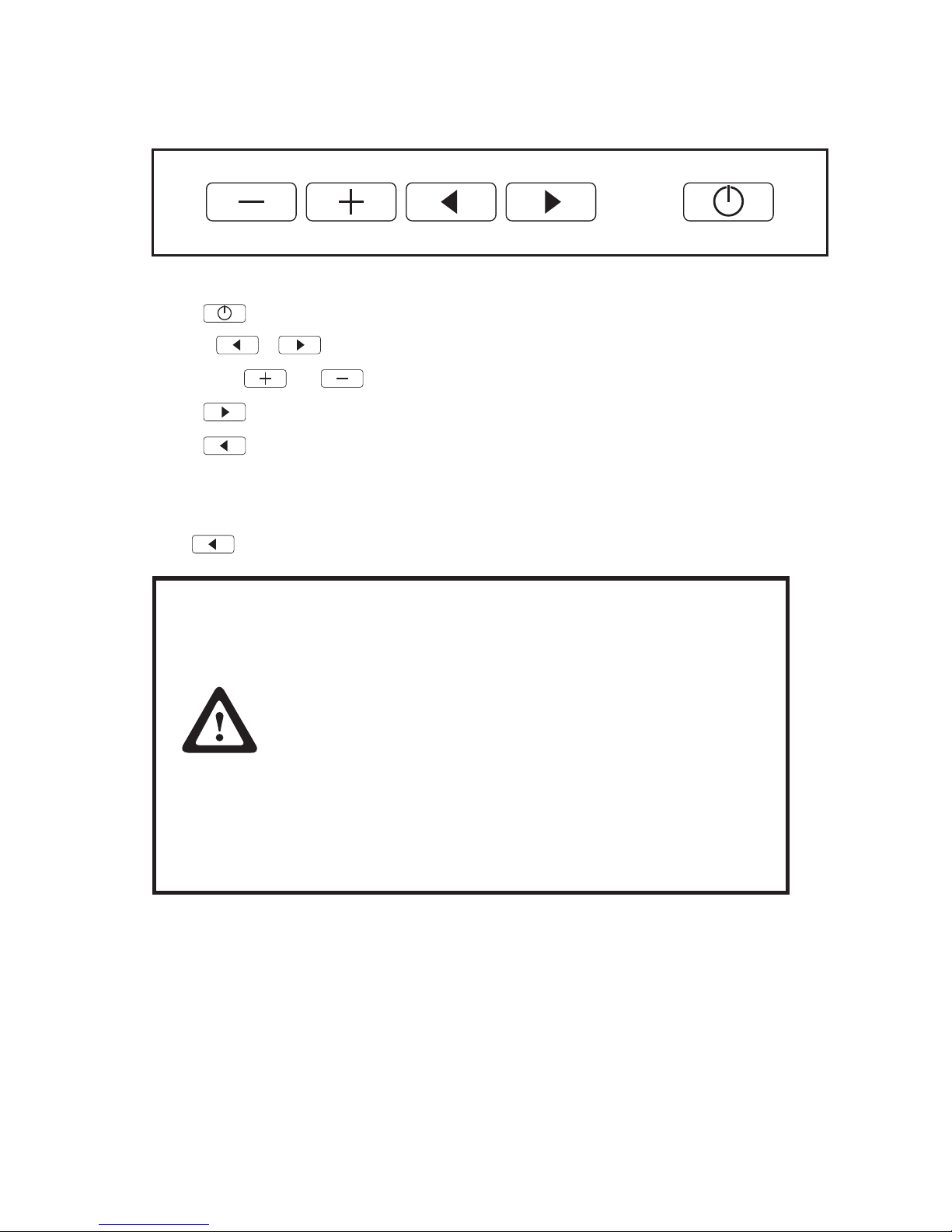
There are Five keys on the PM15 real button of.
Their locations and functions are described as followed:
The • is used for Power On/Off.
Keys: • + can be used to enable OSD.
Normally, • and are used to adjust speaker volume or adjust OSD values.
The • is used for moving up.
The • is used for auto adjusting or moving down.
Auto Adjusting4.1
Press , PM15 will automatically adjust.
IMPORTANT
Important information regarding the AUTO TUNING function.
Most video cards differ as to the video signal output. For
this reason, the PM15 monitor may need to be readjusted
after connecting it to a computer. The factory setting of the
monitor is set to produce the best results with a variety of
industry standard video cards.
By doing this, the display tries to nd the best possible
adjustment. Please note that this Auto Adjusting must be
done for each display mode.
In some cases when using a notebook computer, it might be
necessary to deactivate the internal display of the notebook
in order to obtain a good picture quality.
Page 8
4
Using the On Screen Display (OSD)
5
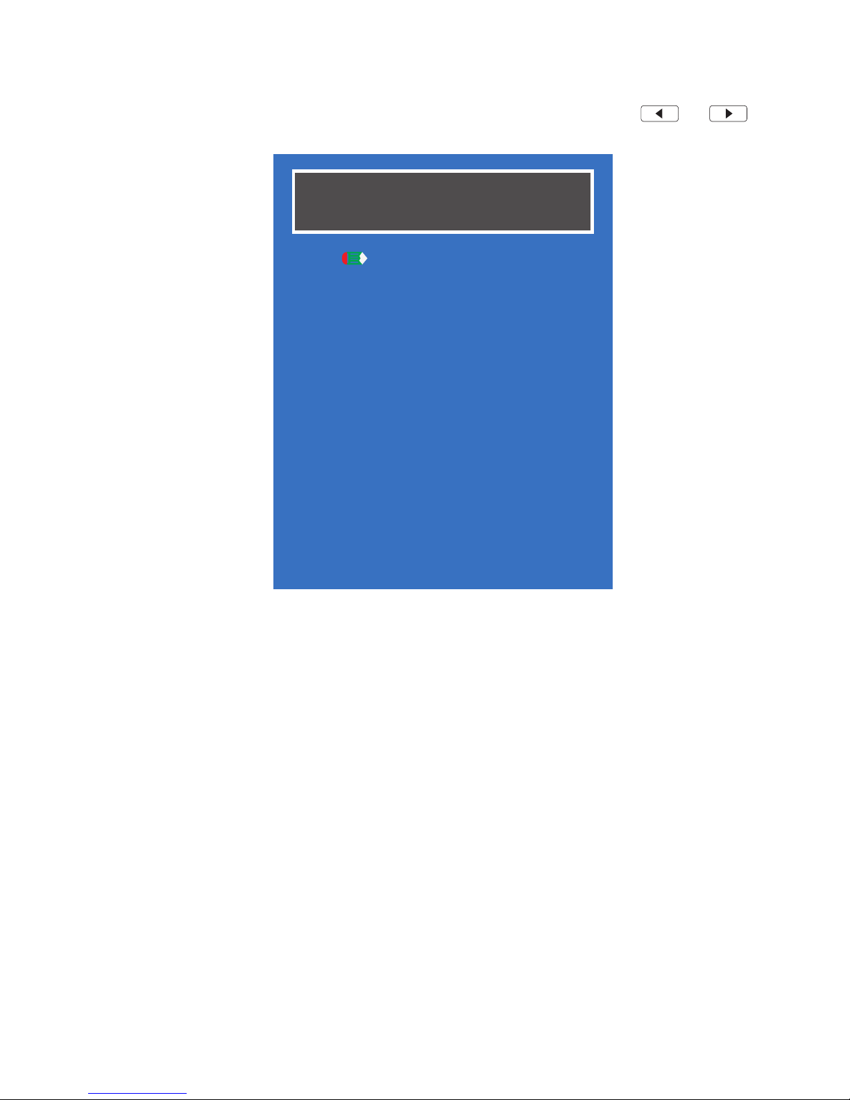
OSD function allows the user to easily adjust the display to the desired quality. Press and
simultaneously to pop up the OSD menu.
Color
Image Setting
Position
OSD Menu
Language
Misc.
Exit
AP145S 1.00
1024x768 85Hz
OSD Function5.1
Color
Contrast / Brightness / Color Adjust / Color Temp
Image Setting
Clock / Phase / Gamma / Sharpness
Position
H.Position / V.Position
OSD Menu
OSD H.Pos. / OSD V.Pos. / OSD Timer
Language
English / Français / Deutsch / Español / 繁體中文 / 简体中文 / 日本語
Misc.
Reset / Volume
Exit
Page 9
5
Contrast5.2
This item is used to adjust contrast. Please follow the steps below to enter the submenu and adjust the
value.
Press 1. and simultaneously to pop up the OSD menu.
Press 2. or to select “Color”.
Press 3. or to enter the submenu.
Press 4. or to select “Contrast”.
Press 5. or to adjust the value.
Brightness5.3
This item is used to adjust Brightness. Please follow the steps below to enter the submenu and adjust
the value.
Press 1. and simultaneously to pop up the OSD menu.
Press 2. or to select “Color”.
Press 3. or to enter the submenu.
Press 4. or to select “Brightness”.
Press 5. or to adjust the value.
Color Adjust5.4
This item is used to adjust Red, Green, Blue color. Please follow the steps below to enter the submenu
and adjust the value.
Press 1. and simultaneously to pop up the OSD menu.
Press 2. or to select “Color”.
Press 3. or to enter the submenu.
Press 4. or to select “Color Adjust”.
Press 5. or to enter the submenu.
Press 6. or to select “Red”, “Green” or “Blue”.
Press 7. or to adjust the value.
Page 10
6
Color Temp5.5
This item is used to change the color intensity of the temperature selected. Please follow the steps
below to select the color temperature.
Press 1. and simultaneously to pop up the OSD menu.
Press 2. or to select “Color”.
Press 3. or to enter the submenu.
Press 4. or to select “Color Temp”.
Press 5. or to enter the submenu.
Press 6. or to select the color temperature.
Clock5.6
This item is used to correct ickering text or lines. Please follow the steps below to enter the submenu
and adjust the value.
Press 1. and simultaneously to pop up the OSD menu.
Press 2. or to select “Image Setting”.
Press 3. or to enter the submenu.
Press 4. or to select “Clock”.
Press 5. or to adjust the value.
Phase5.7
This item is used to correct ickering text or lines. You can not manually set the phase, it can only be
automatically adjusted in accordance with the following steps.
Press 1. and simultaneously to pop up the OSD menu.
Press 2. or to select “Image Setting”.
Press 3. or to enter the submenu.
Press 4. or to select “Phase”.
Press 5. or to auto adjust the phase.
Gamma5.8
This item is used to select the gamma correction, it changes the luminance of the colors with
intermediate luminance. Please follow the steps below to enter the submenu and select the gamma
correction.
Press 1. and simultaneously to pop up the OSD menu.
Press 2. or to select “Image Setting”.
Page 11
7
Press 3. or to enter the submenu.
Press 4. or to select “Gamma”.
Press 5. or to select the gamma correction.
Sharpness5.9
This item is used to change the clearance of image. Please follow the steps below to enter the submenu
and adjust the value.
Press 1. and simultaneously to pop up the OSD menu.
Press 2. or to select “Image Setting”.
Press 3. or to enter the submenu.
Press 4. or to select “Sharpness”.
Press 5. or to adjust the value.
H.Position5.10
This item is used to adjust screen horizontal position. Please follow the steps below to enter the
submenu and adjust the value.
Press 1. and simultaneously to pop up the OSD menu.
Press 2. or to select “Position”.
Press 3. or to enter the submenu.
Press 4. or to select “H.Position”.
Press 5. or to adjust the value.
V.Position5.11
This item is used to adjust screen vertical position. Please follow the steps below to enter the submenu
and adjust the value.
Press 1. and simultaneously to pop up the OSD menu.
Press 2. or to select “Position”.
Press 3. or to enter the submenu.
Press 4. or to select “V.Position”.
Press 5. or to adjust the value.
Page 12
8
OSD H.Pos.5.12
This item is used to adjust OSD horizontal position. Please follow the steps below to enter the submenu
and adjust the value.
Press 1. and simultaneously to pop up the OSD menu.
Press 2. or to select “OSD Menu”.
Press 3. or to enter the submenu.
Press 4. or to select “OSD H.Pos.”.
Press 5. or to adjust the value.
OSD V.Pos.5.13
This item is used to adjust OSD vertical position. Please follow the steps below to enter the submenu
and adjust the value.
Press 1. and simultaneously to pop up the OSD menu.
Press 2. or to select “OSD Menu”.
Press 3. or to enter the submenu.
Press 4. or to select “OSD V.Pos.”.
Press 5. or to adjust the value.
OSD Timer5.14
This item is used to set the length of time the OSD screen is displayed. Please follow the steps below to
enter the submenu and adjust the value.
Press 1. and simultaneously to pop up the OSD menu.
Press 2. or to select “OSD Menu”.
Press 3. or to enter the submenu.
Press 4. or to select “OSD Timer”.
Press 5. or to adjust the value.
Language5.15
You can choose one of seven languages in the Language submenu. Please follow the steps below to
enter the submenu and select the language.
Press 1. and simultaneously to pop up the OSD menu.
Press 2. or to select “Language”.
Press 3. or to enter the submenu.
Page 13
9
Press 4. or to select the language you want to use.
Press 5. or to set.
Reset5.16
This item is used to recall the default settings. Please follow the steps below to enter the submenu and
reset.
Press 1. and simultaneously to pop up the OSD menu.
Press 2. or to select “Mics.”.
Press 3. or to enter the submenu.
Press 4. or to select “Reset”.
Press 5. or to execute reset.
Volume5.17
This item is used to adjust the speaker volume. Please follow the steps below to enter the submenu and
adjust the value.
Press 1. and simultaneously to pop up the OSD menu.
Press 2. or to select “Mics.”.
Press 3. or to enter the submenu.
Press 4. or to select “Volume”.
Press 5. or to adjust the value.
Driver Installation
6
Touchscreen6.1
IMPORTANT
A new calibration is always necessary if another touch
screen was connected to the computer or if the screen
resolution was changed. This means that the calibration
between touch screen and computer is adjusted to the
mechanical features of the particular touch screen which
was connected to the computer at that time.
A serial Touch Controller is integrated into the Touch
Commander. The default setting is 9600 Bps. Normally this
is clearly recognized by the setup programs. If, however,
it is not clearly recognized, the adjustment can be done
manually or by restarting the corresponding setup program.
Page 14
10
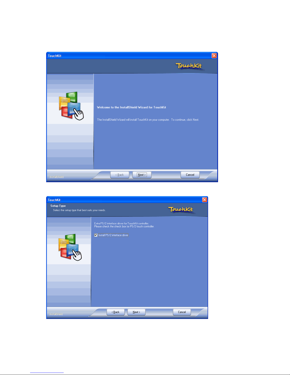
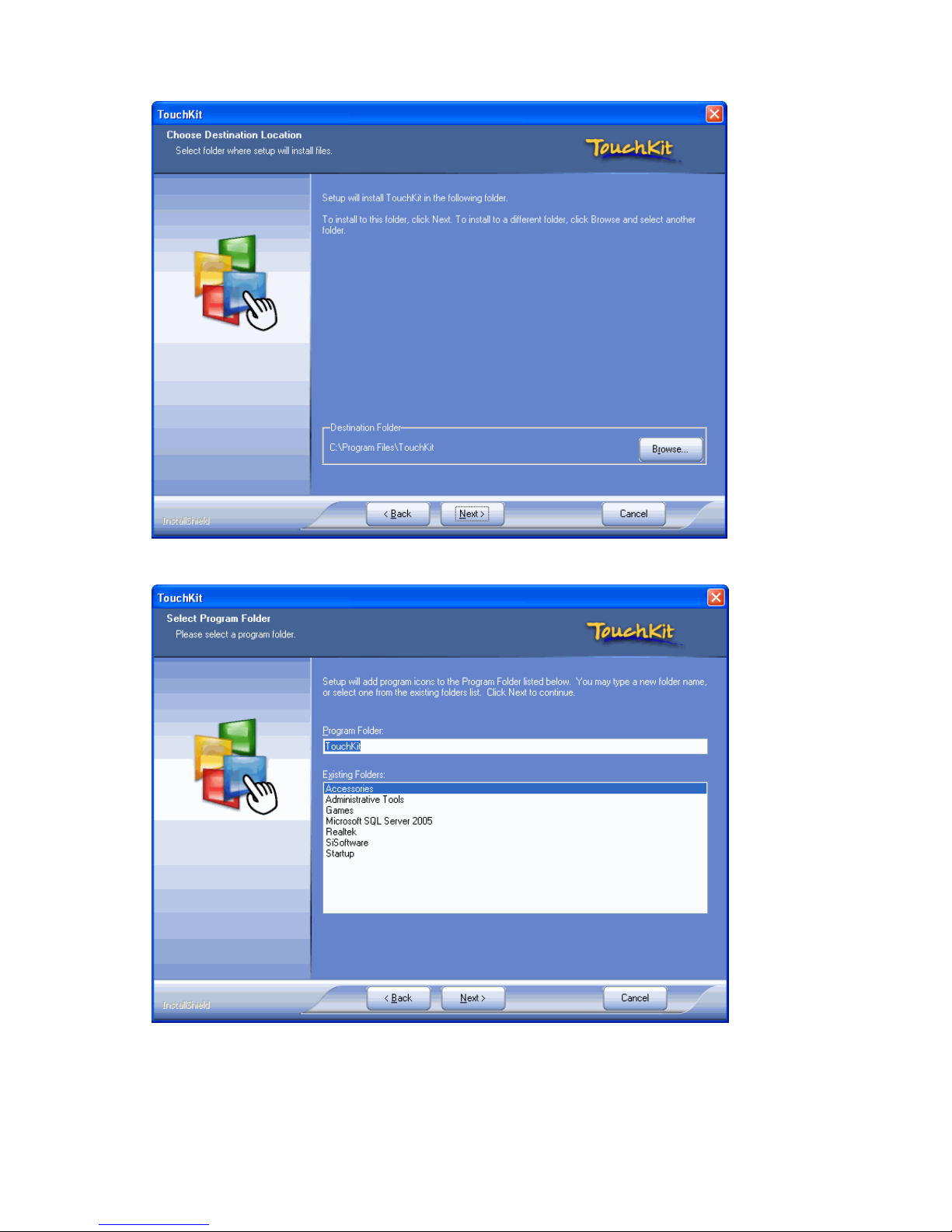
Refer to the following to install the touch screen driver.
Browse to the \DRIVER\Touch\eGalax folder.1.
Double-click setup.exe. The following screen appears. Click 2. Next to continue.
Check the box for 3. Install PS/2 interface drive and then click Next to continue.
Page 15
11
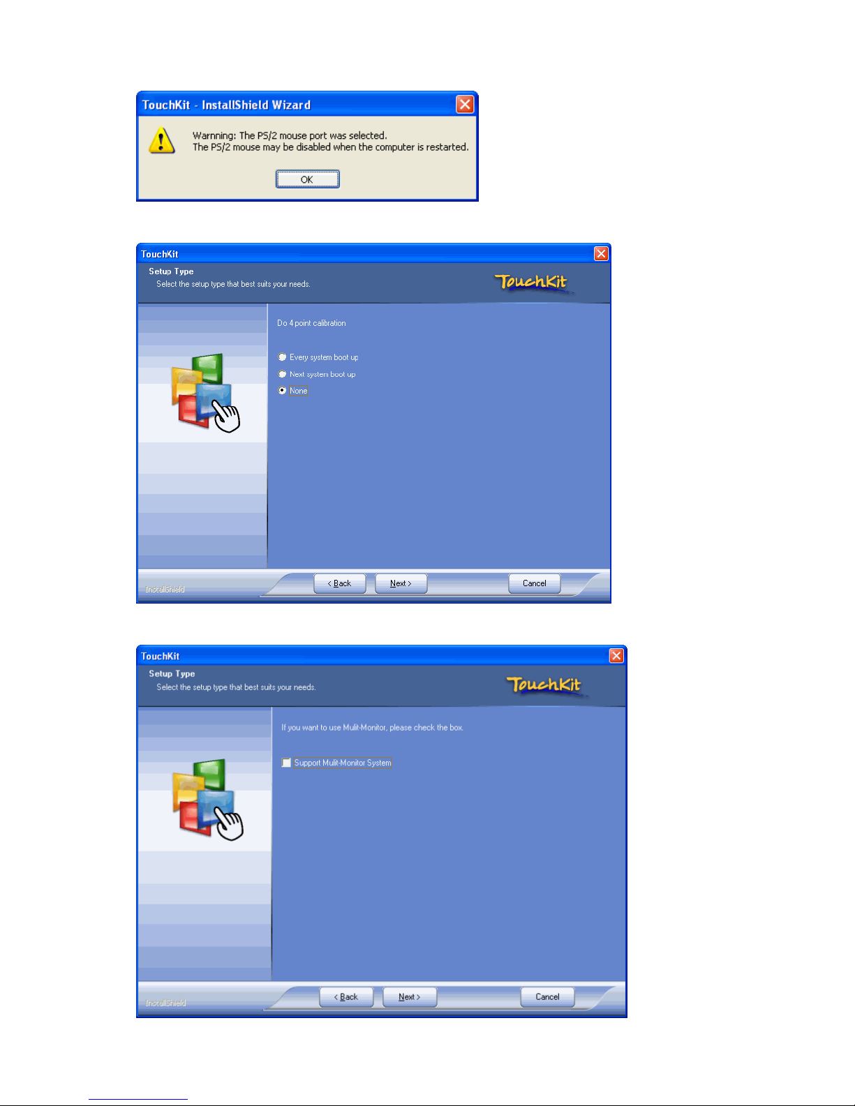
System will give you a warning, click 4. Ok to continue.
Check the box for 5. None and then click Next to continue.
Uncheck the box for 6. Support Mulit-Monitor System and then click Next to continue.
Page 16
12
Click 7. Next to continue.
Click 8. Next to continue.
Page 17
13
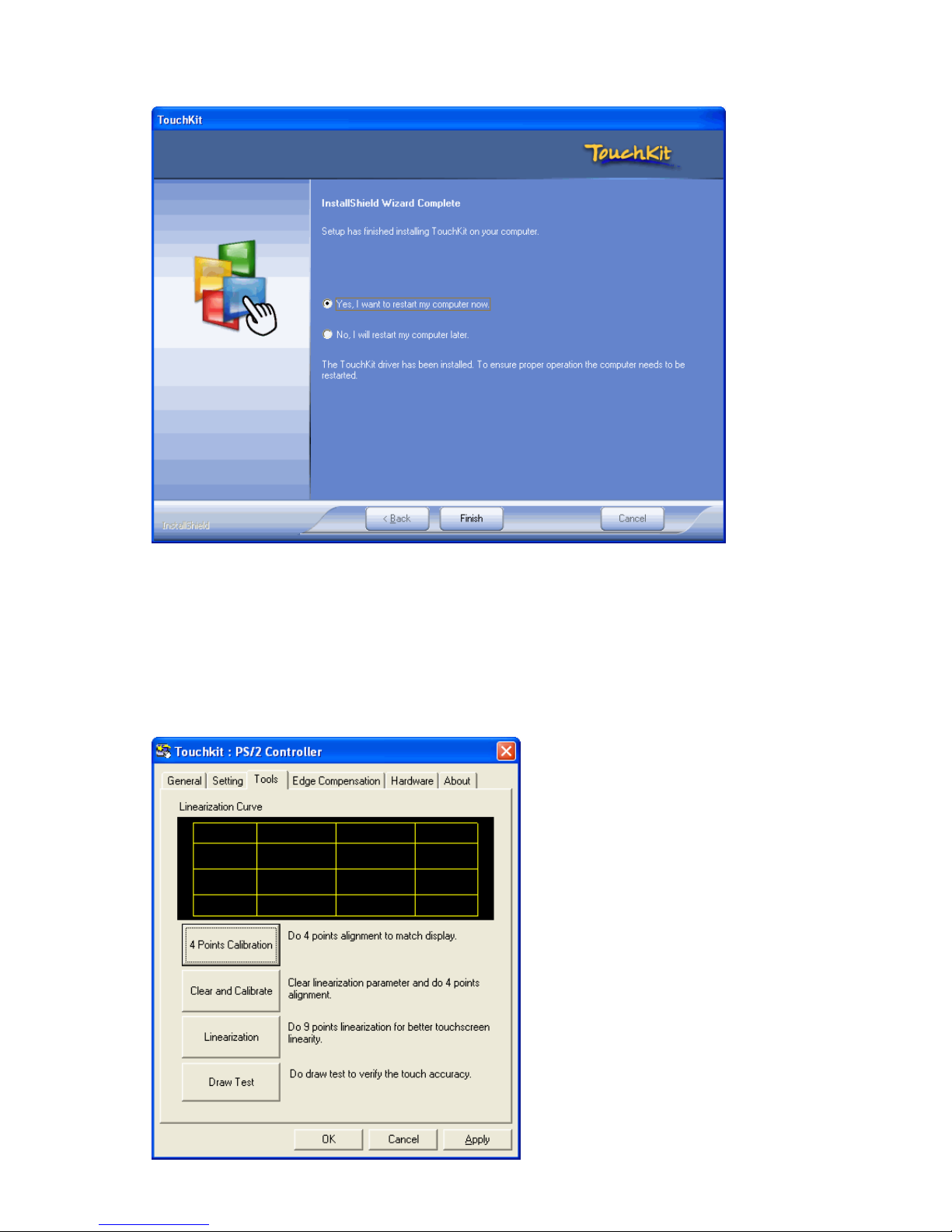
Click 9. Yes, I want to restart my computer now and then click Finish.
Calibrating the touchscreen6.2
Follow these instructions to calibrate the touchscreen using the TouchKit application:
Launch the TouchKit application from the Windows desktop by clicking on 1. Start > Programs >
TouchKit > Congure Utility. The TouckKit window appears.
Select the 2. Tools page.
Page 18
14
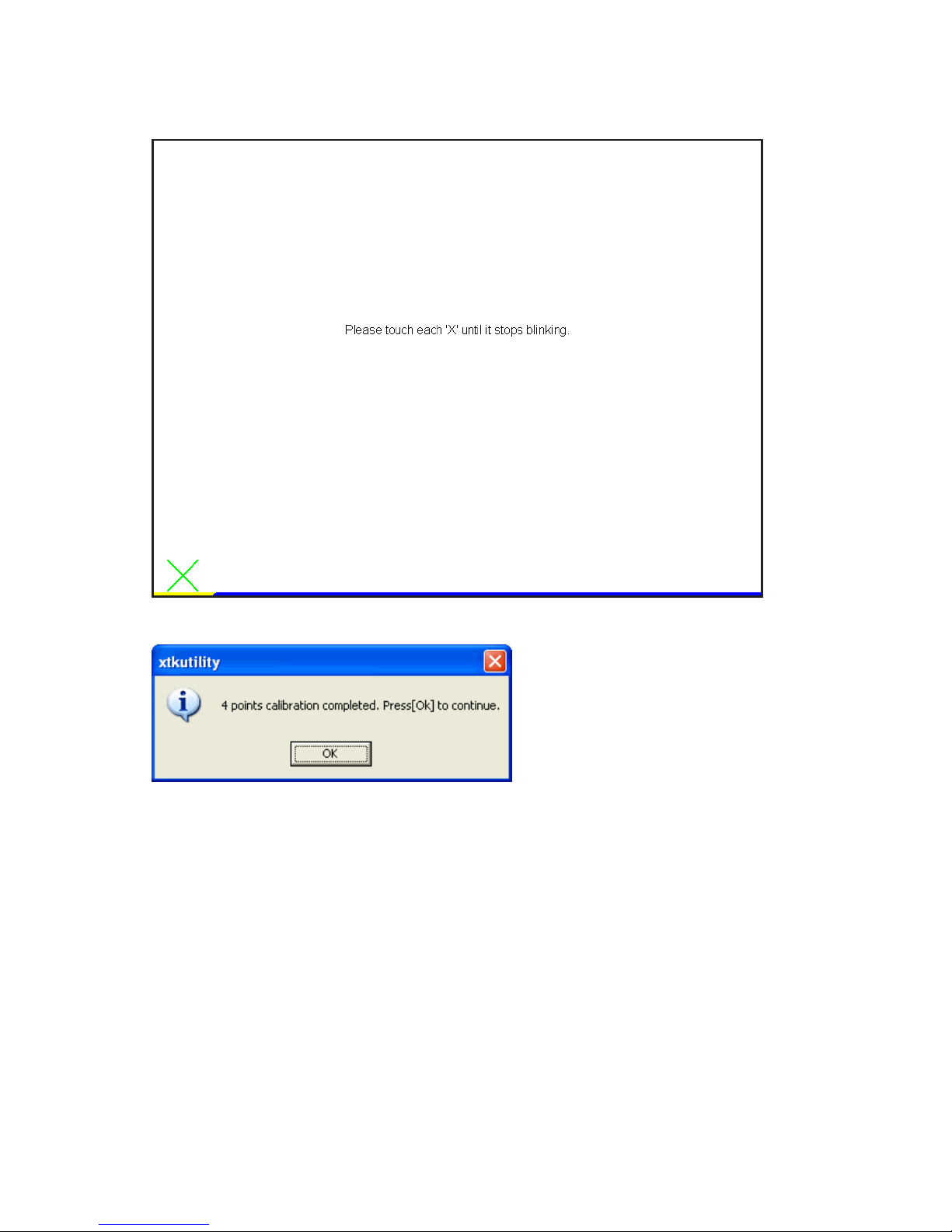
Click the 3. 4 Points Calibration button.
Use your nger to touch the blinking X Symbol on the screen until stop blinking.4.
Click 5. OK to complate the 4 points calibration.
Maintenance and Care
7
Before cleaning, switch off the power supply. A soft cloth moistened with a mild cleaning agent can be
used for cleaning the housing. For cleaning the screen it is better to use a soft paper towel moistened
with a mild household cleaning agent. For cleaning the surface do not apply the cleaning liquid directly
but use a moistened paper towel. Please avoid getting liquid into the housing.
Page 19
15
General Points
8
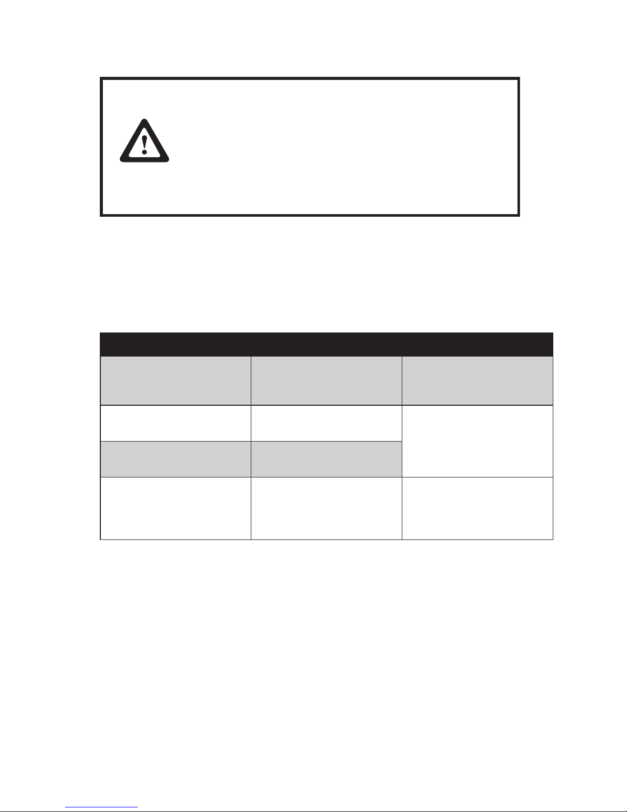
Attention
The Touch / Screen Commander do not contain any electronic
components that can be replaced or repaired by the user.
Consequently you should not try to do your own repair work.
Moreover, you would lose all warranty claims for this product.
Activating the touch sensor surface must not be done with
a sharp object, such as credit card, long nger nails, ring,
etc. Sharp or pointed objects will cause damage to the touch
sensor and are not covered under warranty.
If the Touch/Screen Commander must be returned for service, it must be packed in it’s original packing
material. If this is not done, the sender will be made responsible for possible transport damage.
Troubleshooting
9
Many problems can be the result of an incorrect or loose cable connection, so please make sure that all
connections are secure.
Fault Possible Remedy
The display shows only part
of the picture or the picture is
distorted.
Display resolution is set to an
incompatible setting.
Resolution should be set to
1024X768 or less.
LCD shows indistinct vertical
stripes.
Display H.POSITION is not
set correctly.
Use the Auto Adjusting
feature. (see Section 4.1)
LCD shows ne horizontal
stripes.
PHASE adjustment is not
correctly set.
Touch cannot be calibrated
under Windows because the
calibrate button is not active.
USB cable connection may be
incorrect.
Check USB cable connection
and restart computer. While
booting, check for any
indication of driver errors.
Additional help9.1
If you have problems with the connection or the installation of the PM15 monitor, please contact your
distributor or direct to the manufacturer:
Partner Tech Corp.
Tel: +886-2-29188500
Fax: +886-2-29153405
www.partner.com.tw
When returning the device, the original packing must be used; otherwise the sender will be responsible
for any transport damage.
Page 20
16
Technical Data
10
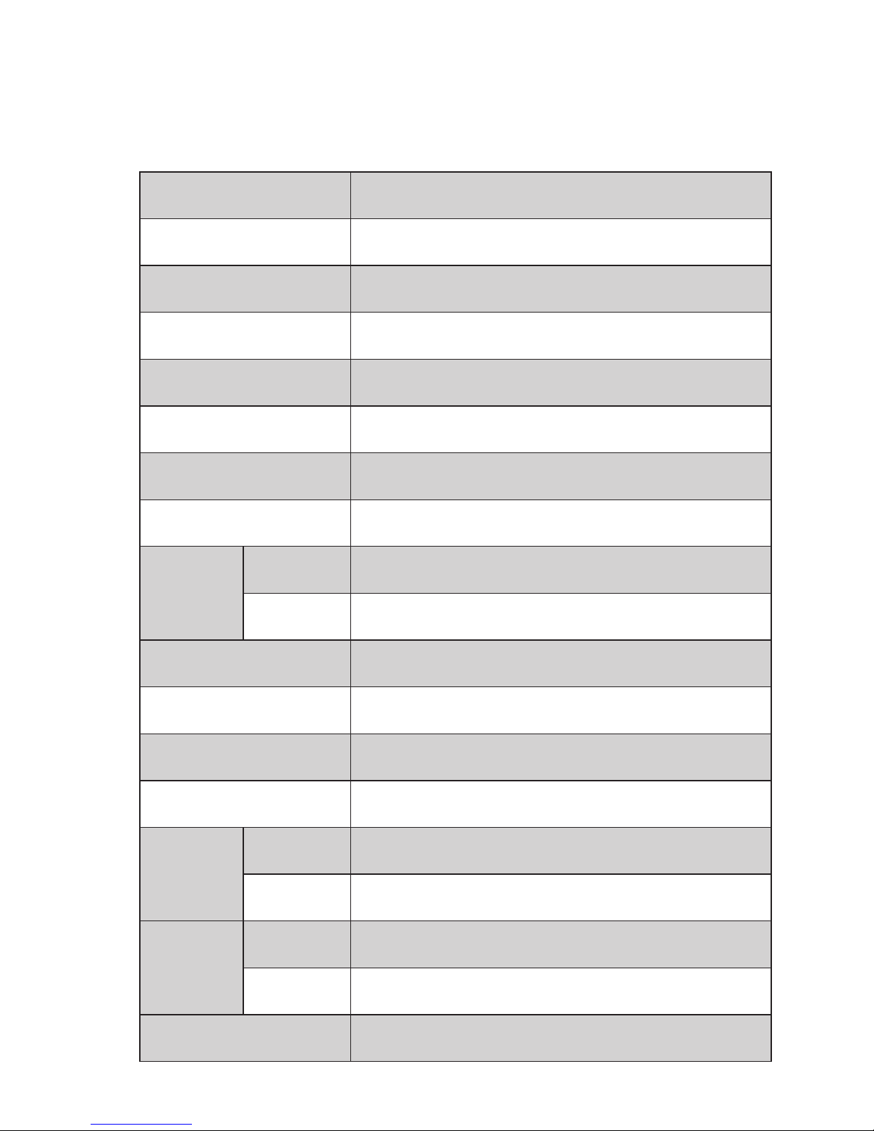
Product Specication10.1
Model name PM-15
LCD Display 15” TFT panel
Pixel Pitch 0.297(H)x0.297(V) mm
Max. Resolution XGA 1024x768
Contrast Ratio 500
Brightness 250 cd/m2(Typ) (without touch)
Display Color 16.2 M colors
Touch Screen Resistive touch with RS232 or USB interface connector
Viewing
Angle
L/R 70˚~ 70˚(Typ)
U/D 65˚~ 55˚(Typ)
OSD (On Screen Display) Power , Left , Right , Up , Down
Speaker 2 W Active Speaker
Power adaptor AC 100V ~ 240V/ DC12V/4.16A 50 watt
Option Singal MSR/Multi MSR/KB32
Operating
Conditions
Temperature 0˚C - 40˚C (32˚F - 104˚F)
Humidity 20%~ 85%
Storage
Conditions
Temperature -10˚C - 60˚C (-4˚F - 140˚F)
Humidity 5%~ 85%
Certication CE, FCC, BSMI, VCCI, LVD, CCC
Page 21

17
Safety Instructions
11
This product is TUV / CB and UL approved.
Note:
Do not ingest the liquid crystal from a broken LCD. If your skin comes into contact with liquid •
crystal, wash it with soap immediately.
Please observe the installation instructions before connecting the PM15 to any device.•
Due to some high voltage components, it is advisable to not open the unit, as it may cause severe •
electrical shock or burns. All repair work for the device should be sent to a qualied service center.
Do not operate the device without the enclosure. Make sure no objects or liquids get into the interior •
through openings in the housing.
Further Notices
12
The PM15 monitor is subject to a continuous process of improvement. For this reason we reserve the
rights to make any technical modications.
We point out that inadequate handling, storage, inuence and/or modication can cause disturbances
and damage in usage.
In case you modify the product in any way we do not assume warranty and liability unless you have an
explicit release in writing for your specic case. This applies especially to unprofessional repair and
maintenance jobs.
Any claims for damages against the manufacturer of the PM15 – no matter for which legal reasons are
excluded if no intention and gross negligence can be proved. Above limitations do not apply to claims
for damages out of the product liability law.
This User Manual is exclusively written for the PM15 monitor.
Warranty
13
The manufacturer of the PM15 monitor guarantees that all products supplied are free from production
and material defects.
Statement of Confirmation
14
This is to certify that statements of conrmation are available for all different variations of the PM15
monitor.
You can order them directly from your distributor stating the exact monitor type.
(See model number label on the bottom of the device)
Page 22
18
FCC Warning Statement
15
This equipment has been tested and to comply with the limits for Class A or Class B (modular foot)
digital device, pursuant to Part 15 of the FCC Rules. These limits are designed to provide reasonable
protection against harmful interference in a residential installation. This equipment generates uses and
can radiate radio frequency energy and, if not installed and used in accordance with the instructions,
may cause harmful interference to radio communications. However, there is no guarantee that
interference will not occur in a particular installation. If this equipment does cause harmful interference
to radio or television reception, which can be determined by turning the equipment on and off, the user
is encouraged to try to correct the interference by one of the following measures:
Reorient or relocate the receiving antenna.•
Increase the separation between the equipment and receiver.•
Connect the equipment into an outlet on a circuit different from that to which the receiver is con-•
nected.
Consult the dealer or an experienced radio/TV technician for help.•
Shielded interface cables must be used in order to comply with the emission limits.
Caution
Changes or modications not expressly approved by the party
responsible for compliance could void the user’s authority to
operate the equipment.
 Loading...