

Page 1

Operator’s manual
Read these instructions carefully and
make sure you understand them
before using the machine.
K950 RING
Page 2
2 – English
WARNING! The power cutter can be
dangerous! Careless and incorrect use can
result in serious or fatal injury to the
operator or others.
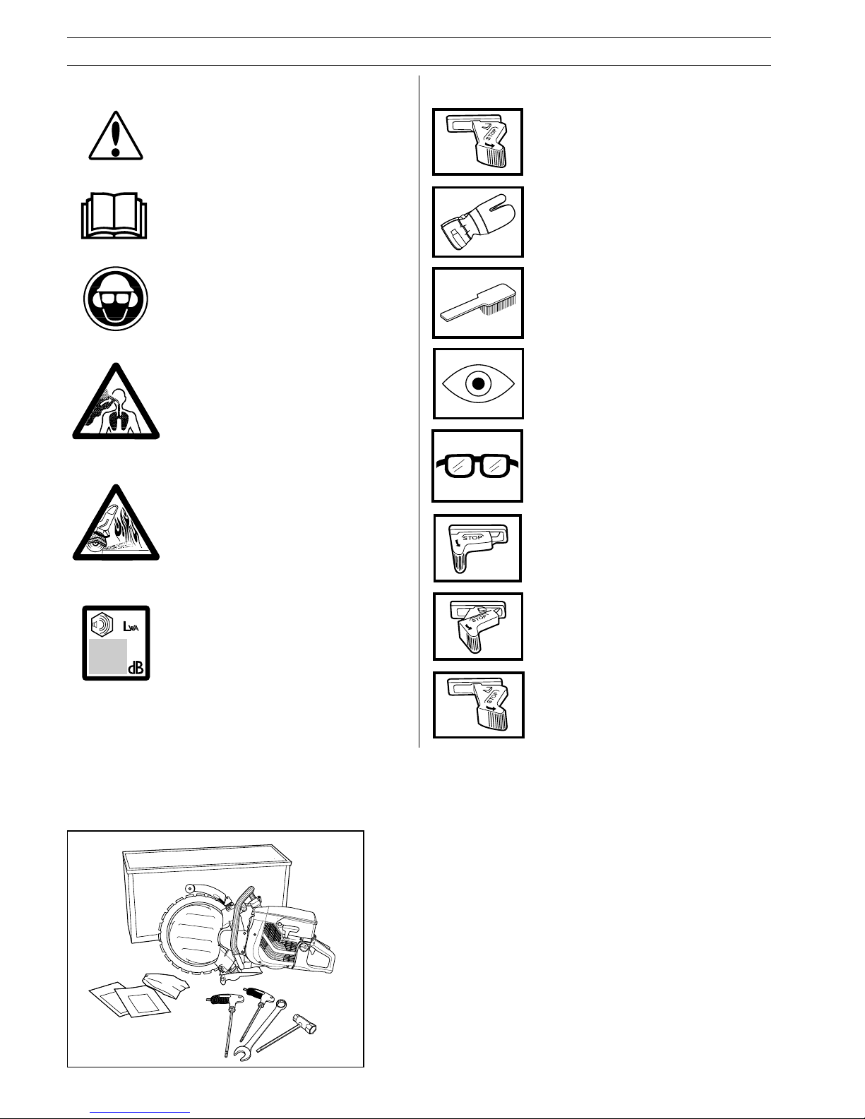
SYMBOL EXPLANATION
Symbols on the power cutter:
Please read the instructions carefully and
make sure you understand them before
using the power cutter.
Always wear:
• Approved protective helmet
• Approved hearing protection
• Protective glasses or visor
Switch off the engine by moving the stop
switch to the fixed STOP position before
carrying out any checks or maintenance.
Symbols in the Operator's Manual:
Warning
Cutting creates a lots of dust which can
cause inhalation damages. Use appropriate
dust mask or respirator protection. Avoid
breathing petrol fumes and exhaust gases.
Provide for good ventilation.
Warning
Sparks from the cutting blade can cause
fire in combustible materials such as: petrol
(gas), wood, dry grass etc.
Protective glasses or a visor must be
worn.
Visual check.
Regular cleaning is required.
Always wear approved protective gloves.
Run position.
Stop with spring loaded return to Run
position.
Stop, in fixed position.
1 K950 ring power cutter
1 Wooden carrying case
1 Tool kit
1 Operator’s manual
1 Illustrated parts list
The Partner K950 ring power cutter a hand-held power
cutter that cuts 260 mm (10") with a 350 mm (14")
blade.
This design is exclusive to Partner Industrial Products,
and is another example of Partner’s continuous
commitment to design excellence.
THE PARTNER K950 RING INCLUDES:
Noise emission to the environment
according to the European Community’s
Directive. The machine’s emission is
specified in chapter Technical data and on
label.
Page 3

English – 3
CONTENTS
List of Contents
Symbol explanation ..................................................... 2
Safety instructions
Personal protective equipment....................................... 4
The power cutter’s safety equipment ...................... 4
Control, maintenance and service of the machine‘s safety
equipment ............................................................................ 5
General safety instructions .............................................. 6
Transport and storage ......................................................... 6
Fuel safety ........................................................................... 7
General working instructions........................................... 7
Cutting ................................................................................. 7
Kickback .............................................................................. 8
Care and storage ................................................................. 9
Diamond blades................................................................... 9
What is what?
What is what on a power cutter? ....................................... 10
Set up and adjustments
Drive Principle ................................................................... 11
Blade Installation ............................................................... 12
Removal of engagement roller compl. ............................... 14
Installation of engagement roller compl. ............................ 14
Drive Disc .......................................................................... 15
Support Rollers/Engagement Rollers ................................ 15
Fuel handling
Fuel mixture ....................................................................... 16
Fuelling .............................................................................. 16
Start and stop
Start and stop .................................................................... 17
Maintenance
Adjusting the drive belt ...................................................... 18
Belt tensioning/changing the drive belt .............................. 18
Belt pulley and clutch......................................................... 18
Carburetor ......................................................................... 18
Fuel filter ............................................................................ 19
Air filter .............................................................................. 19
Starter ................................................................................ 20
Spark plug ......................................................................... 21
Cooling system .................................................................. 21
Muffler ............................................................................... 21
Blade Retipping ................................................................. 21
Daily maintenance ............................................................. 22
Weekly maintenance ......................................................... 22
Monthly maintenance ........................................................ 22
Technical Data
K950 Ring .......................................................................... 23
Troubleshooting ................................................................. 24
Before using your new Power cutter
• Read the Operator’s Manual carefully.
• Check the assembly and adjustment of the cutting blade, see
chapter
”Set up and adjustments”.
• Start the engine and check the carburettor settings. See
chapter ”Maintenance”, section ”Carburettor”. When adjusted
correctly the cutting blade should not rotate when idling.
Setting the idling speed is described in the Operator’s
Manual. Adjust the speed according to these instructions. Do
not use the power cutter if the idling speed is not correctly
adjusted!
• Let your Partner dealer check the power cutter and carry out
essential adjustments and repairs.
Partner Industrials has a policy of continuous product
development and therefore reserves the right to modify the
design and appearance of products without prior notice.
All information and data in this manual were in effect at the time
this manual was approved for printing.
WARNING!
Under no circumstances should you modify
the original design of the power cutter without
approval from the manufacturer. Always use
genuine spare parts. Unauthorized
modifications or accessories may lead to
serious injury or death.
!
WARNING!
Use of products which cut, grind, drill, sand or
shape material can generate dust and vapors
which may contain harmful chemicals. Know
the nature of the material being worked on
and wear appropriate dust mask or respirator
protection.
!
Page 4
4 – English
!
SAFETY INSTRUCTIONS
!
!
WARNING! Incorrect or careless use of a
power cutter can turn it into a dangerous tool
that can cause serious or even fatal injury. It
is extremely important that you read and
understand this manual.
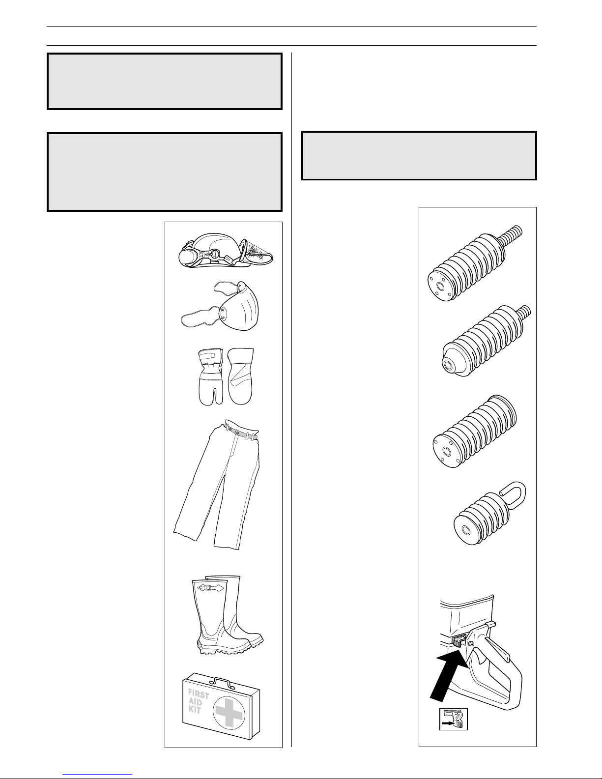
PERSONAL PROTECTIVE EQUIPMENT
WARNING! When using a power cutter
approved protective equipment must be used.
Personal protective equipment does not
eliminate the risk of accidents, however, it can
reduce the effects of an injury in the event of
an accident. Ask your dealer for help when
choosing protective equipment.
• PROTECTIVE HELMET
• EAR PROTECTION
• PROTECTIVE GLASSES
OR FULL FACE
PROTECTION
• BREATHING MASK
• HEAVY-DUTY, FIRM GRIP
PROTECTIVE GLOVES
• SNUG-FITTING, HEAVYDUTY, COMFORTABLE
CLOTHING THAT ALLOWS
FULL FREEDOM OF
MOVEMENT
• LEG PROTECTION (TO
PROTECT AGAINST
SPARKS AND CUTTING
FRAGMENTS)
• ANTI-SLIP BOOTS WITH
STEEL TOE CAPS
• FIRST AID KIT SHOULD
ALWAYS BE ON HAND
THE POWER CUTTER’S SAFETY
EQUIPMENT
This section describes the power cutter’s safety equipment, its
function and how checks and maintenance are carried out to
ensure that it operates correctly. (See the chapter
“What is
what“
to locate where this equipment is positioned on your
power cutter.)
WARNING! Never use a power cutter with
defective safety equipment. Follow the
control, maintenance and service instructions
described in this manual.
1 Anti-vibration
system
Your power cutter is equipped
with an anti-vibration system.
This is designed to give as low
vibration levels and
comfortable usage as possible.
The power cutter’s antivibration system reduces the
transfer of vibration between
the engine/cutting equipment
and the operator. The engine
body including the cutting
equipment is suspended in a
handle system via antivibration elements.
2 Stop switch
The stop switch should be
used to stop the engine.
Page 5
English – 5
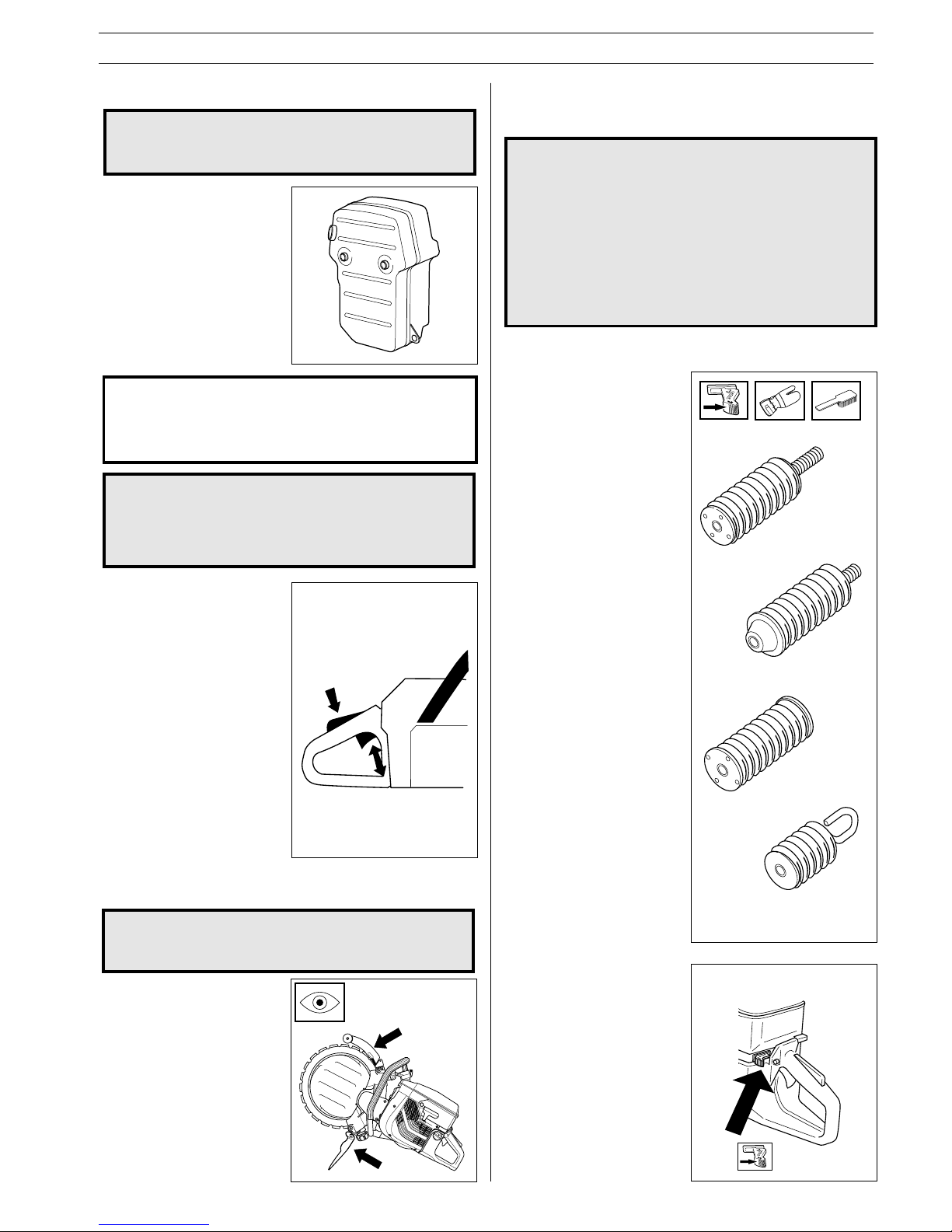
1 Anti-vibration system
Check the anti-vibration
elements regularly for material
cracks and deformation.
Check that the anti-vibration
elements are securely
mounted between the engine
unit and the handle system.
Keep handles clean and dry.
The muffler is designed to
give the lowest possible noise
level and to direct the engine‘s
exhaust fumes away from the
user. The engine‘s exhaust
fumes are hot and can contain
sparks, which can lead to the
outbreak of fire.
!
SAFETY INSTRUCTIONS
3 Muffler
!
WARNING! During use and for some time
after the muffler is very hot. Do not touch the
muffler if it is hot!
2 Stop switch
Start the engine and make
sure that the engine stops
when the stop switch is
moved to the stop position.
IMPORTANT INFORMATION! It is extremely important that
the instructions for checking, maintaining and servicing
the muffler are followed. (see the section
“Control,
maintenance and service of the power cutter’s safety
equipment“
).
!
Control, maintenance and service of
the machine‘s safety equipment
WARNING! All service and repairs to the
power cutter require special training. This
applies especially to the power cutter’s safety
equipment. If the power cutter does not meet
any of the controls listed below you should
contact your service workshop.
The purchase of one of our products
guarantees that professional repair and
servicing will be carried out on it. If the point
of purchase is not one of our servicing
dealers, please ask for details of the closest
service workshop.
5 Blade guard for the cutting blade
WARNING! Always check that the blade guard
is correctly fitted before starting the machine.
The blade guard is mounted
above the cutting blade and
prevents cutting fragments
from being thrown towards the
user.
A
B
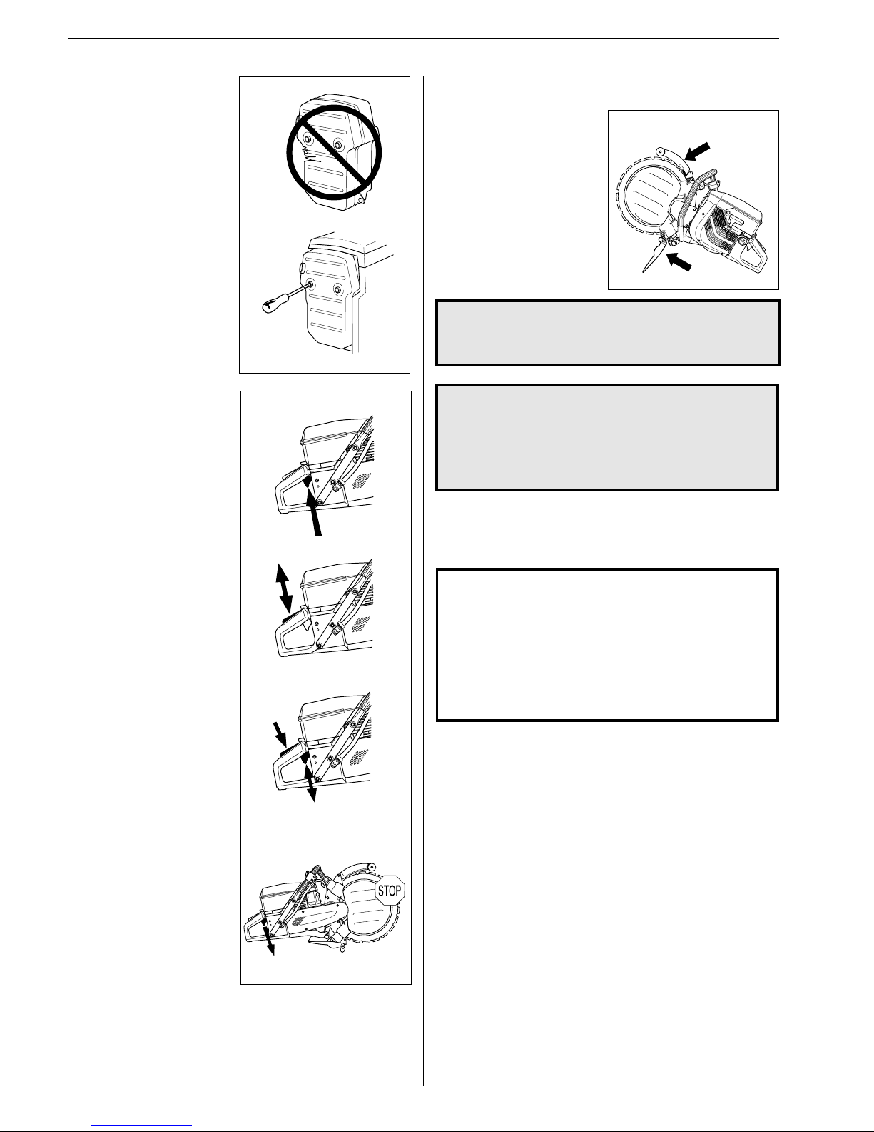
4 Throttle lock
The throttle lock is designed
to prevent accidental operation of the throttle control.
When you press the lock (A)
(i.e. when you grasp the
handle) it releases the throttle
trigger (B). When you release
the handle the throttle trigger
and the throttle lock both
move back to their original
positions. This movement is
controlled by two independent
return springs. This arrangement means that the throttle
control is automatically locked
at the 5le setting when you
release the handle.
WARNING! The insides of mufflers fitted with
catalytic converters contain chemicals that
may be carcinogenic. Avoid contact with
these elements in the event of a defective
muffler.
!
Page 6
6 – English
SAFETY INSTRUCTIONS
GENERAL SAFETY INSTRUCTIONS
3 Muffler
Never use a machine that has
a defective muffler.
Check regularly that the
muffler is secured to the
engine body.
!
!
WARNING! Never use a power cutter with
defective safety equipment. The power
cutter’s safety equipment should be checked
and maintained as described in this
Operator’s Manual. If your power cutter does
not meet any of these controls you should
contact your service workshop.
5 Blade guard for the cutting blade
Never use a defective blade
guard or a blade guard that is
not fitted correctly.
WARNING! Check that the cutting blade is
fitted correctly and does not show signs of
damage. A damaged cutting blade can cause
personal injury.
Transport and storage
• Store the power cutter in a lockable area so that it is out of
reach for children and unauthorised persons.
• Never use the machine when you are tired, under the
influence of medicines/drugs or alcohol.
• Never start a power cutter indoors. Be aware of the dangers
of inhaling the engine´s exhaust fumes.
• Do not lend out the power cutter without including this
Operator’s Manual. Ensure that the person who intends to
use the power cutter understands the information in the
Operator’s Manual.
Intended use
IMPORTANT INFORMATION!
A power cutter is designed to cut hard materials such
as concrete/stone. Observe the increased risk of
kickback when cutting soft materials.
Do not use the power cutter until you have read the
entire contents of this Operator´s Manual.
All servicing, in addition to the points listed in the
section "
Control, maintenace and service of the power
cutter´s safety equipment
", should be carried out by
trained service specialists.
4 Throttle lock
1 Make sure the throttle
control is locked at the
idle setting when you
release the throttle lock.
2 Press the throttle lock and
make sure it returns to its
original position when you
release it.
3 Check that the throttle
control and throttle lock
move freely and that the
return springs work
properly.
4 Start the power cutter and
apply full throttle. Release
the throttle control and
check that the blade stops
and remains stationary. If
the blade rotates when
the throttle is on idle
setting you should check
the carburettor idle
adjustment. See the
section on
”Maintenance”
.
Page 7
English – 7
Fuel safety
(Filling/Fuel mixture/Storage)
WARNING! Exercise great care when handling
fuel. Bear in mind the risk of fire, explosions
and inhaling fumes.
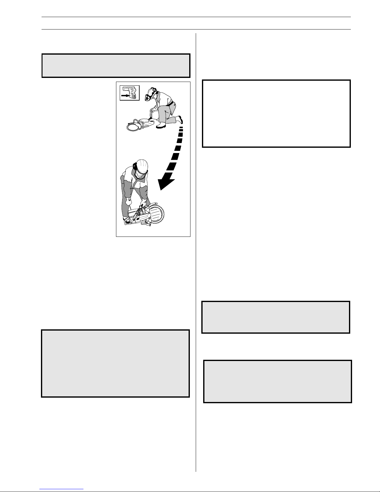
• Never fill the machine while
the engine is running.
• Provide good ventilation
when filling or mixing fuel
(gasoline and 2-stroke oil).
• Move the machine at least 3
m from the filling position
before starting.
• Never start the machine:
a) If you have spilt fuel
on it. Wipe up all
spillage.
b) If you have spilt fuel
on yourself or your
clothes. Change your
clothes.
c) If there is a fuel leak.
Make regular checks for
leakage from the fuel
cap and the fuel supply
pipes.
• Store the power cutter and fuel so that any leakage or fumes
do not risk coming into contact with sparks or naked flames.
For example, electric machines, electric motors, electrical
switches/power switches, heaters or the like.
• When storing fuel, approved containers intended for this
purpose must be used.
• When storing the power cutter for long periods the fuel tank
must be emptied. Contact your local fuel station to find out
how to dispose of excess fuel.
• Use a Partner fuel can with an anti-spill device.
SAFETY INSTRUCTIONS
!
!
WARNING! Use a Partner fuel can with an
anti-spill device. Fuel and fuel fumes are
highly flammable. Think of the risks of fire,
explosion and breathing in fumes. Stop the
engine before refuelling. Do not overfill with
fuel. Mop up any spills on the ground or the
machine. If you spill fuel on yourself or your
clothes, change your clothes. Move the
machine at least 3 metres from the refuelling
site before starting.
GENERAL WORKING INSTRUCTIONS
This section takes up the basic safety precautions for working
with the power cutter. Follow these general working instructions,
but never use a machine without the possibility of calling for
help in the event of an accident.
Basic safety precautions
IMPORTANT INFORMATION! Never work with a power
cutter that is defective or incorrectly adjusted. Do not
work with a power cutter that is incomplete or where
assembly has not been carried out in a satisfactory
manner. Check that the cutting blade stops rotating
when the throttle is released. If you encounter a situation
where you are uncertain how to proceed you should ask
an expert.
Avoid all usage which you consider to be beyond your
capability.
• Check that no one is in the immediate vicinity when the
machine is started or while working with the machine to
ensure that people, animals or other things cannot affect your
control of the power cutter.
• Avoid usage in unfavourable weather conditions, for example,
thick fog, heavy rain, strong winds or extreme cold, etc. To
work in bad weather conditions is tiring and can create
dangerous circumstances, e.g. slippery surfaces.
• Never start to work with the power cutter before the working
area is clear and you have a firm foothold. Look out for any
obstacles with unexpected movement. Ensure when cutting
that no material can become loose and fall, causing operating
injury.Take great care when working on sloping ground.
• Make sure clothing and parts of the body do not come into
contact with the cutting blade when the engine is started.
• Maintain a safe distance from the cutting blade when the
engine is running.
• The blade guard should always be fitted when the engine is
running.
• Ensure that the working area is sufficiently illuminated to
create a safe working environment.
• Do not move the power cutter with the blade rotating.
• Make sure that no pipes or electrical cables are routed in the
area to be cut.
WARNING! A safe distance from the power
cutter is 15 metres. You are responsible that
animals and onlookers are not in the working
area. Do not start to work with the power
cutter before the working area is clear and
you have a firm foothold.
• Start cutting with the engine at full throttle.
• Always hold the power cutter firmly, with both hands. Hold
the machine so that the thumb and fingers grip around the
handle.
Cutting
Only use the machine in areas with good
ventilation. Neglect can result in serious
injury or death. Carbon monoxide in the
exhaust fumes causes suffocation.
!
!
Min 3 m (10ft)
Page 8
8 – English
SAFETY INSTRUCTIONS
!
Over exposure to vibrations can result in
blood-vessel or nerve injury to persons
suffering with blood circulation problems.
Seek medical attention if you experience
physical symptoms that can be related to over
exposure to vibrations. Examples of such
symptoms are numbness, lack of feeling,
“tickling“, “pricking“, pain lack of or a
reduction in normal strength, changes in the
colour of the skin or its surfaces. These
symptoms normally appear in the fingers,
hands or wrists.
!
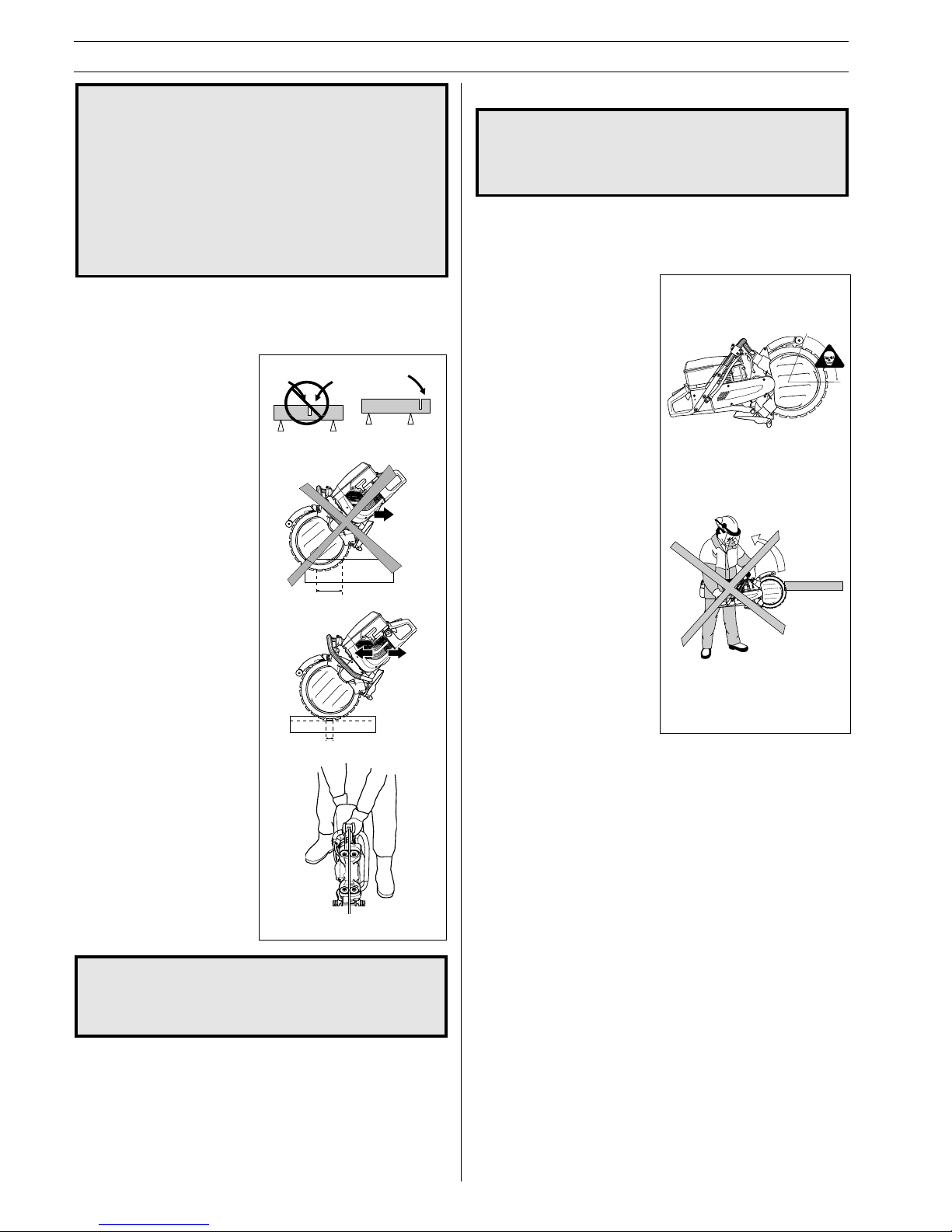
Cutting technique
The technique described below is of a general character.
1.Support the work piece
in such away that you
can predict what will
happen and so it will not
pinch.
2.Always cut at full throttle.
3.Start cutting gently, do
not force or push the
blade in.
4.Use a high blade speed.
5.Move the blade slowly
backwards and forwards.
6.Use a small part of the
blade’s cutting edge.
7.Only use the blade’s
cutting edge when
cutting.
8.Cut with the blade fully
vertical – at right angles
to the work piece.
WARNING!
Do not lean the blade to the side, this can
cause the blade to jam or break with personal
injury as a consequence.
Kickback
If the sector of the blade illustrated below is used for cutting the
blade can start to climbing and kickback the power cutter
upwards and backwards towards the user with immense force.
How to avoid kickback
1.Never cut with the
segment illustrated in the
diagram.
2.Keep a good balance and
a firm foothold.
3.Use both hands and take
a firm grip with the thumb
and fingers around the
handle.
4.Keep the work piece at a
comfortable distance.
5.Use the cutter at full
throttle.
6.Take care when inserting
the blade in an existing
cut.
7.Never cut above shoulder
height.
8.Be alert to movement of
the work piece or anything
else that can occur, which
could cause the cut to
close and pinch the blade.
!
WARNING!
Kickback can occur very suddenly and with
great force. If the following directives are not
followed, it can result in serious or even fatal
injury.
Page 9
English – 9
SAFETY INSTRUCTIONS
!
WARNING!
If the speed is higher than that stated then the
unit must be adjusted by an authorised
service workshop before it is used.
Pull in
Pull in occurs when the lower part of the blade is suddenly
stopped or when the cut closes. (To avoid this see the section
”
How to avoid kickback
” and
”Pinching/rotation”
below).
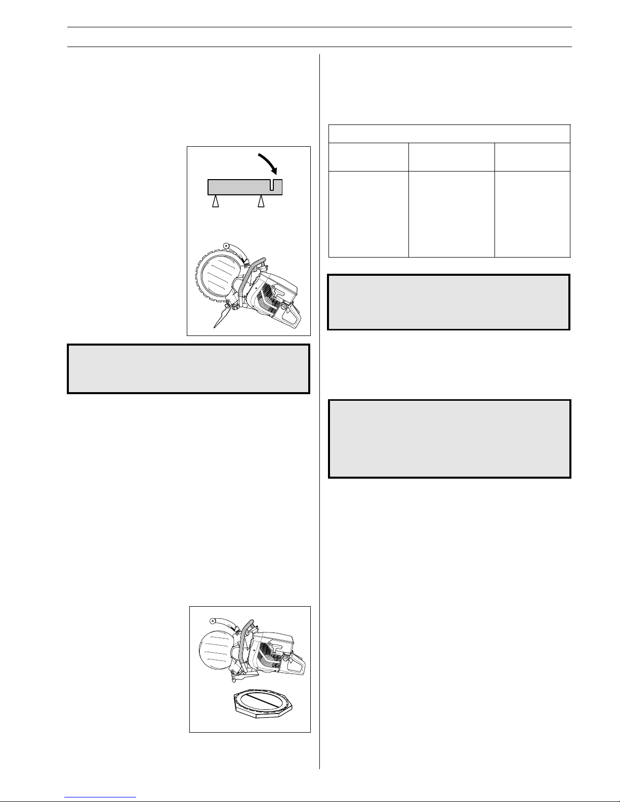
Pinching/rotation
Pinching occurs when the cut closes. The power cutter can be
drawn suddenly and powerfully downwards.
How to avoid pinching
Support the work piece in
such a way that the cut
remains open during the
cutting operation and when
the cut is finished.
Check the engine speed
Use a tachometer regularly
to check the engine speed
when the cutter is running at
working temperature and at
full throttle without a load.
The maximum engine speed
is stated on the machine.
Care and storage
General
Partner’s power cutters are robust and durable. However, as
they are used for high speed operations all servicing should be
carried out on time and as specified, so that the power cutter
always works effectively and safely.
Read this Operator’s Manual to determine which service
routines you can carry out and ensure that all other service
work is carried out by an authorised service workshop.
Power Cutter
Always handle the power cutter with care and store it in the
wooden carrying case in which it is delivered.
Blade
• Inspect new blades for
transport or storage
damage.
!
WARNING!
Cool a diamond blade continously with water
to prevent overheating, which can cause the
blade to break and pieces being thrown off
resulting in injury and damage.
Diamond blades
Diamond blades are manufactured from industrial diamonds
held together by a bonding agent.
Low cost per
cutting operation. Constant
cutting depth.
Less dust.
Increases the
blades service
life.
All brickwork,
reinforced
concrete and
other composite
materials. NOT
recommended for
metal.
DIAMOND BLADES
General char- Material Water cooling
acteristics
Water cooling
!
WARNING! Water cooling, which is used when
cutting concrete, cools the cutting blade and
increases its service life as well as reduce
dust formation. Among the disadvantages are
difficulties at very low temperatures, the risk
of damaging the floor and other sections of
the building and risk for slippage.
Sharpening diamond blades
Blades can become dull when the wrong feeding pressure is
used or when cutting some materials such as heavily reinforced
concrete. To force a dull blade results in overheating and finally
the loss of segments (part of the blade).
Sharpen against a soft material such as sandstone or haydite
brick.
Page 10
10 – English
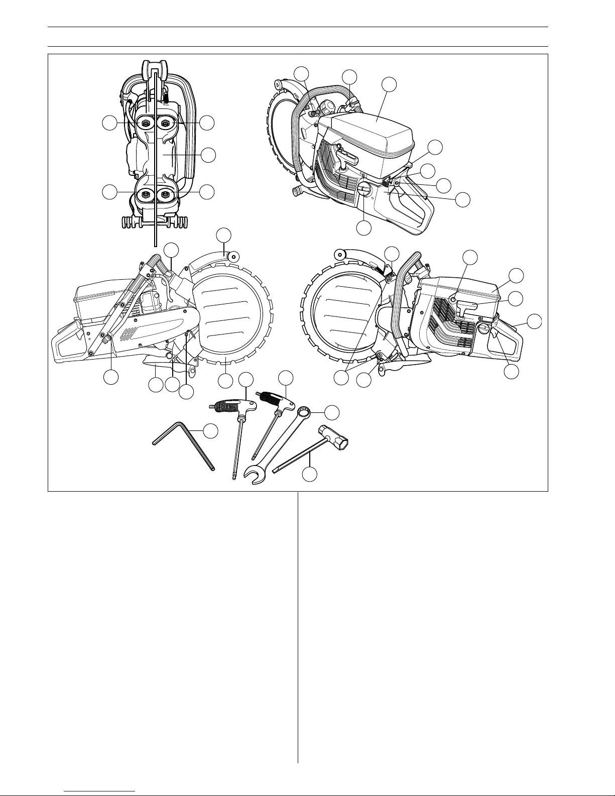
WHAT IS WHAT?
1. Engagement rollers
2. Support rollers
3. Drive disc
4. Lock nuts for support rollers
5. Water flow adjustment valve
6. Choke
7. Stop switch
8. Starter throttle catch
9. Fuel tank
10. Water cooling connection
11. Engagement roller knobs
12. Blade guard/splash guard
13. Lock button for drive disc
14. Ring blade
What is what on a power cutter?
15. Support cover screws
16. Roller adjustment screws
17. Decompression valve
18. Air filter cover
19. Starter handle
20. Throttle trigger lockout
21. Throttle
22. 6 mm T-allen wrench
23. 4 mm T-allen wrench
24. 19 mm Spanner
25. Combination spanner
26. Operator’s manual
27. Warning decal
28. Type plate
9
2
2
3
1
1
4
5
27
6
7
8
28
21
20
19
18
17
15
15
16
12
11
13
12
14
11
10
26
25
23
24
22
Page 11
English – 11
SET UP AND ADJUSTMENTS
Drive Principle
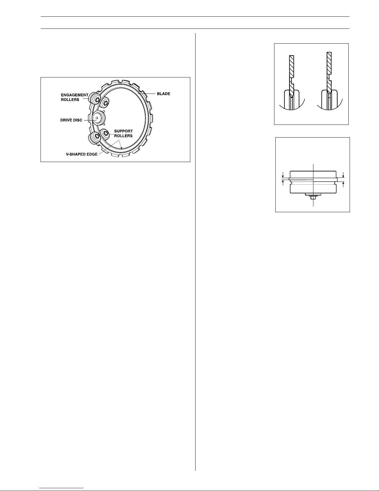
The machine’s unique design allows the blade to be driven by a
belt driven shaft mounted off the center of the blade. This
feature provides a total cutting depth of 260 mm (10 inches)
with a 350 mm (14 inch) wet cutting diamond blade. The
machine is a small, well-balanced and light weight package.
• the engagement rollers are
not overly worn; and
• the adjustment between the
rollers and the blade is
correct.
During the life of a blade, roller
adjustment needs to be
checked twice, once after
installation of a new blade and
once when the blade is worn
50%.
WORN
Min 1,5 mm
(.060")
NEW
3 mm (.120")
ENGAGEMENT ROLLER
Essential Service
As the blade is used, the
inner diameter of the blade,
as well as the groove in the
drive disc, will wear.
The saw will continue to
operate well when:
• the drive disc is not overly
worn; and
WORN
NEW
DRIVE DISC
The shoulders on the two engagement rollers run in the groove
of the blade. The engagement roller springs forces the roller
out, pushing the V-shaped edge of the blade’s inner diameter
against the V-shaped groove of the drive disc. The drive disc is
mounted on a shaft driven by the engine via a belt.
Page 12
12 – English
SET UP AND ADJUSTMENTS
NOTE: Partner offers a
selection of wet cutting ring
blades for different materials.
Check with a Partner dealer
for the blade that is best
suited for your application.
WARNING!
Never retip a used ring blade. A used blade
may not have the proper strength. A retipped
blade may crack or break and cause severe
personal injury to the operator or others.
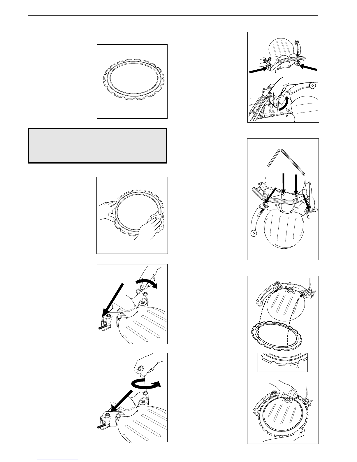
• Wipe blade to remove any
debris from the blade
surface.
• Loosen the locknuts on the
support roller cover.
!
• Unscrew the adjusting
screws a few turns.
• Loosen the knobs to release
all spring tension.
• Remove the four screws
that fasten the support roller
cover with the 6 mm L-allen
wrench and remove the
cover.
• Put the blade on the
machine.
• Next, insert the blade into
the drive disc. Rotate the
blade while installing it onto
the lower engagement
roller. If needed, push in
the engagement rollers, so
that the shoulders on the
engagement rollers enters
the groove on the blade.
NOTE: The blade has a
machined groove on one
side which is the tracking
groove for the engagement
rollers.
Blade Installation
Page 13
English – 13
SET UP AND ADJUSTMENTS
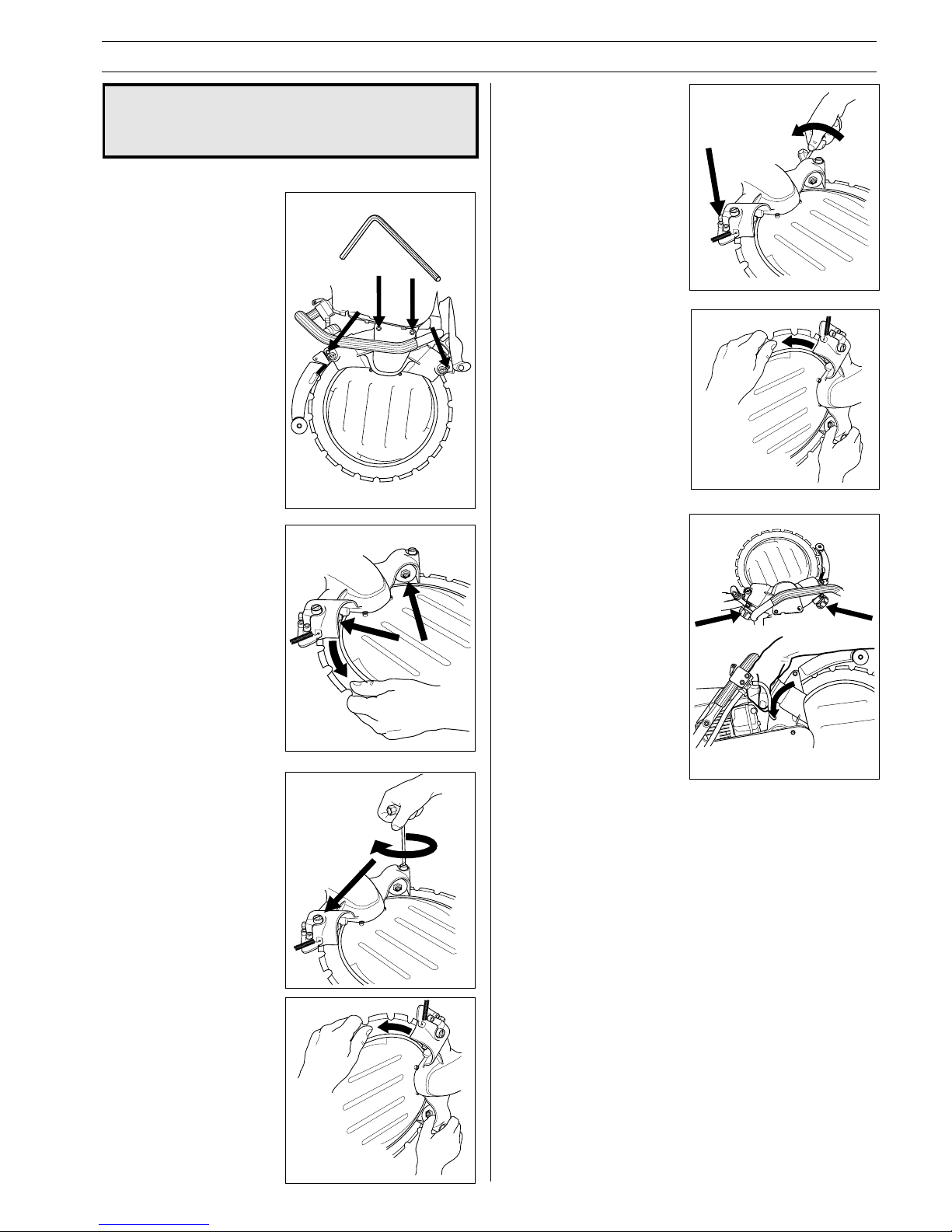
• Assemble the support roller
cover and make sure that
blade groove is aligned with
both engagement rollers.
Then tighten the four
screws tight.
• Turn the blade and check
that the support rollers do
not have tension against
the blade.
• Adjust the support rollers so
that you easily can block the
roller with your thumb when
rotating the blade.
• Tighten the lock nuts on the
support roller cover.
• Rotate the blade and recheck with your thumb that it
is easy to block the roller
when rotating the blade.
NB. The machine should be
placed upright.
• Tighen the knobs hard and
the machine is ready to use.
WARNING!
Inspect the blade for damage before installing
on the unit. Damaged blades can break and
cause severe injury.
!
Page 14
14 – English
SET UP AND ADJUSTMENTS
Installation of engagement roller
compl.
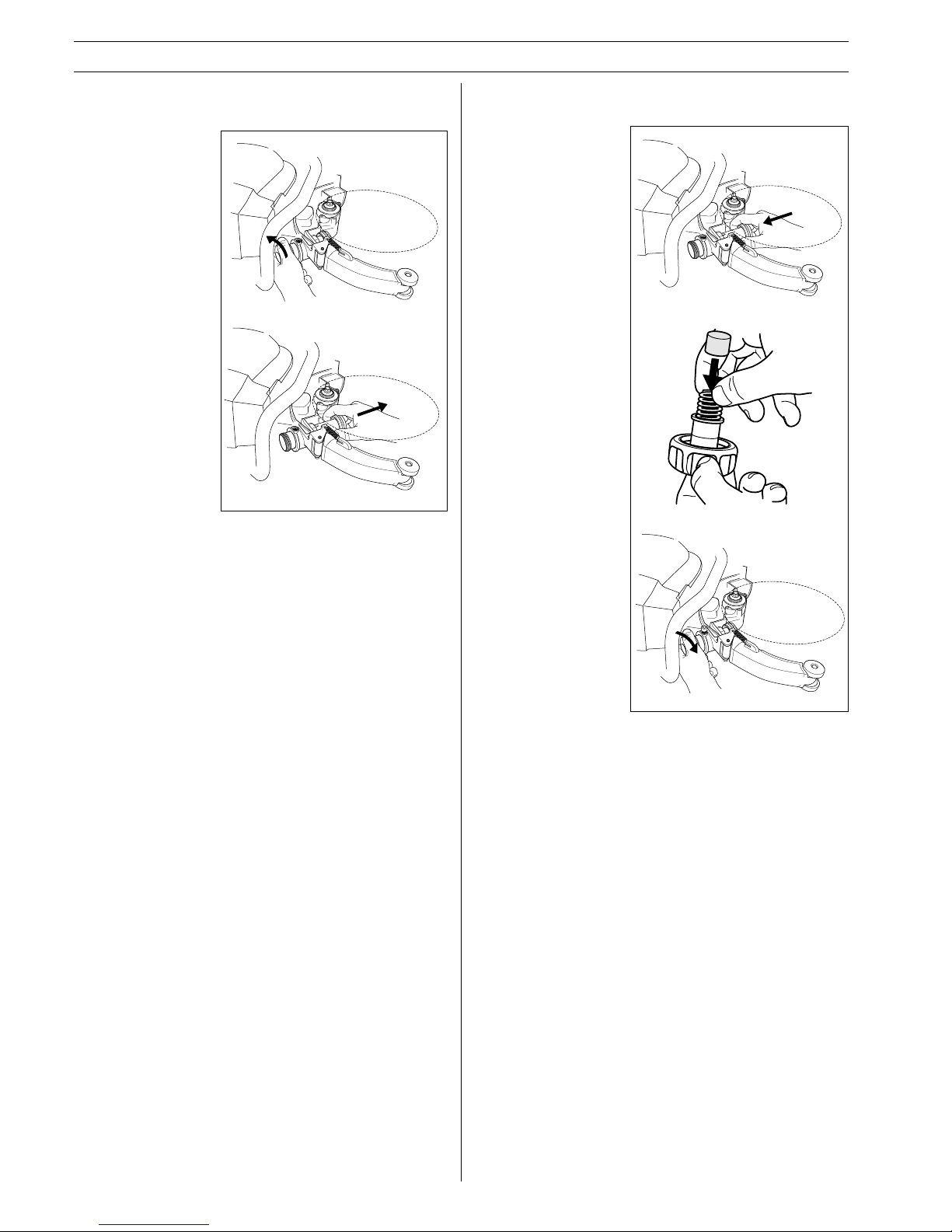
• Apply grease in
the housing, then
push in the
engagement
rollers in the
housing.
• Place the spring
and the plastic
spacer in the
knob.
• Enter the knob
approx. 1/2 turn
on the thread.
• Remove the knob.
Removal of engagement roller compl.
• The engagement roller
compl. can now be
pulled out from the
machine.
Page 15
English – 15
SET UP AND ADJUSTMENTS
Drive Disc
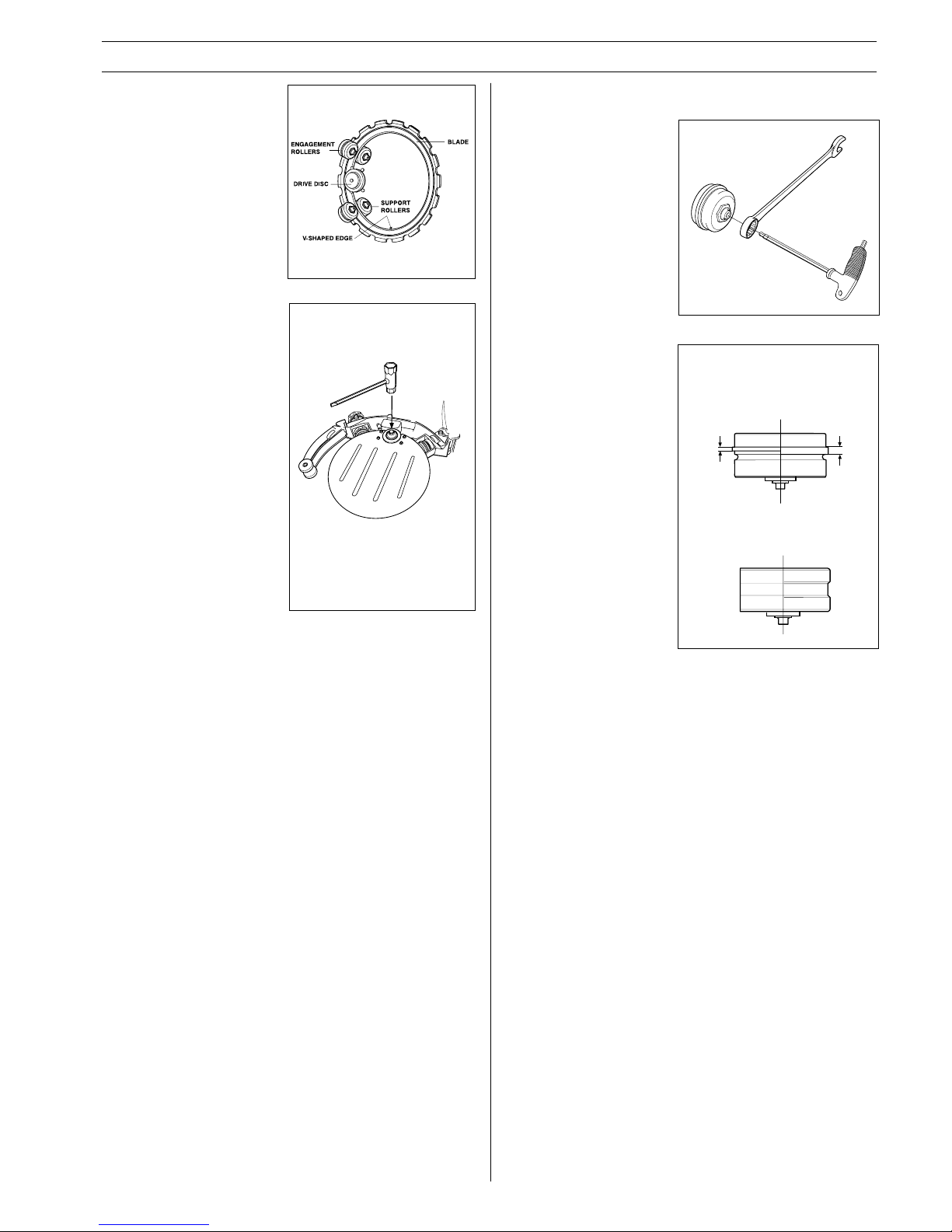
A.Lock the shaft with the lock
button. (see nr 13 page 10).
B.Unscrew the center screw
and remove the washer.
The drive disc can now be
lifted off.
NOTE: Replace the disc when
a new blade is installed.
A worn disc will cause the
blade to slip and damage the
blade.
Lack of water flow will also
drastically reduce the life of
the drive disc.
Support Rollers/Engagement Rollers
• Remove the support
roller cover.
• Check the condition of all
the rollers
• To change the rollers
use the spanner and the
5 mm T-allen wrench.
• Replace the
engagement rollers
when the shoulder or
ridge on the roller is
worn to 50 percent of its
original width.
• Replace support rollers
when roller surface is
flat, (or) when the
groove in roller surface
has disappeared.
WORN
Min 1,5 mm
(.060")
NEW
3 mm
(.120")
WORN
OUT
(No recess
visible)
NEW
IMPORTANT NOTES:
• The support rollers do not
drive the blade.
• Improper adjustment can
lead to blade damage.
• If the blade turns slowly or
stops, see trouble shooting.
SUPPORT ROLLER
ENGAGEMENT ROLLER
Page 16
16 – English
FUEL HANDLING
!
Fuelling
WARNING!The following precautions reduce
the risk of fire:
• Do not smoke or place any sources of heat in
the vicinity of the fuel.
• Never refuel when the engine is running.
• Open the fuel cap slowly when fuelling so
that any over pressure is released slowly.
• Tighten the fuel cap carefully after refuelling.
• Always move the machine from the fuelling
place before starting.
• Keep the handle dry, clean
and free from oil and fuel.
• Clean around the fuel cap.
Clean the fuel tank
regularly. The fuel filter
should be changed at least
once per year
Contamination in the tank
can disrupt operations.
Ensure that the fuel is well
mixed by shaking the
container before filling the
tank.
• Always exercise care when
filling the fuel. Move the
power cutter at least three
metres from the filling area
before starting. Make sure
the fuel cap is tightened.
IMPORTANT! The power cutter is equipped with a two-stroke
engine and must always been run using a mixture of gasoline
and two-stroke engine oil. It is important to accurately measure
the amount of oil to be mixed to ensure that the correct mixture
is obtained. When mixing small amounts of fuel, even small
inaccuracies can drastically affect the ratio of the mixture.
Always provide for good ventilation when
handling fuel.
!
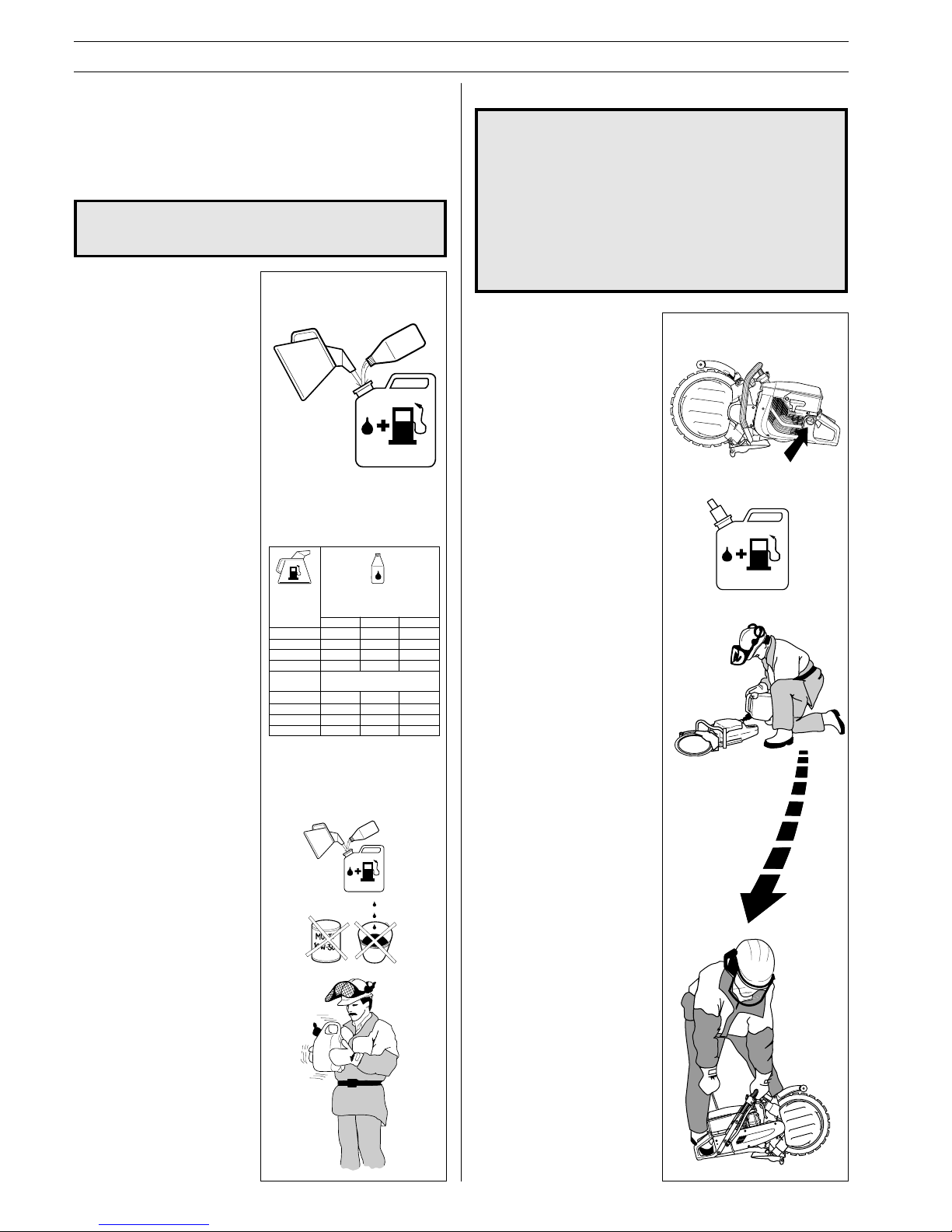
Fuelmix
Petrol
• Use good quality unleaded
or leaded petrol.
• The lowest octane
recommended is 90.
• If you run the engine on a
lower octane grade than 90
so-called, knocking can
occur. This gives rise to a
high engine temperature,
which can result in serious
engine damage.
Two-stroke oil
• For the best results use
PARTNER two-stroke oil,
which is especially
developed for power
cutters. Mixing ratio 1:50
(2%).
• If PARTNER two-stroke oil
is not available, you may
use another two-stroke oil of
good quality that is intended
for air cooled engines.
Contact your dealer when
selecting an oil. Mixing ratio
1:33 (3%)-1:25 (4%).
• Never use two-stroke oil
intended for water cooled
outboard engines, so-called,
outboard oil.
• Never use oil intended for
four-stroke engines.
Mixing
• Always mix the petrol and
oil in a clean container
intended for fuel.
• Always start by filling half
the amount of the petrol to
be used. Then add the
entire amount of oil. Mix
(shake) the fuel mixture.
Add the remaining amount
of petrol.
• Mix (shake) the fuel mixture
thoroughly before filling the
saw’s fuel tank.
• Do not mix more than max.
one month’s supply of fuel.
• If the power cutter is not
used for some time the fuel
tank should be emptied and
cleaned.
5
10
15
20
2%(1:50)
0,10
0,20
0,30
0,40
3%(1:33)
0,15
0,30
0,45
0,60
4%(1:25)
0,20
0,40
0,60
0,80
Gasolin
Benzin
Essence
Gasolina
Lit.
Oil • Öl
Huile • Aceite
Lit.
1
2 1/2
5
2%(1:50)
2 1/2
6 1/2
12 7/8
3%(1:33)
3 3/4
9 3/4
19 1/4
4%(1:25)
5 1/8
12 7/8
25 3/4
US
gallon
US
fl. oz.
Page 17
English – 17
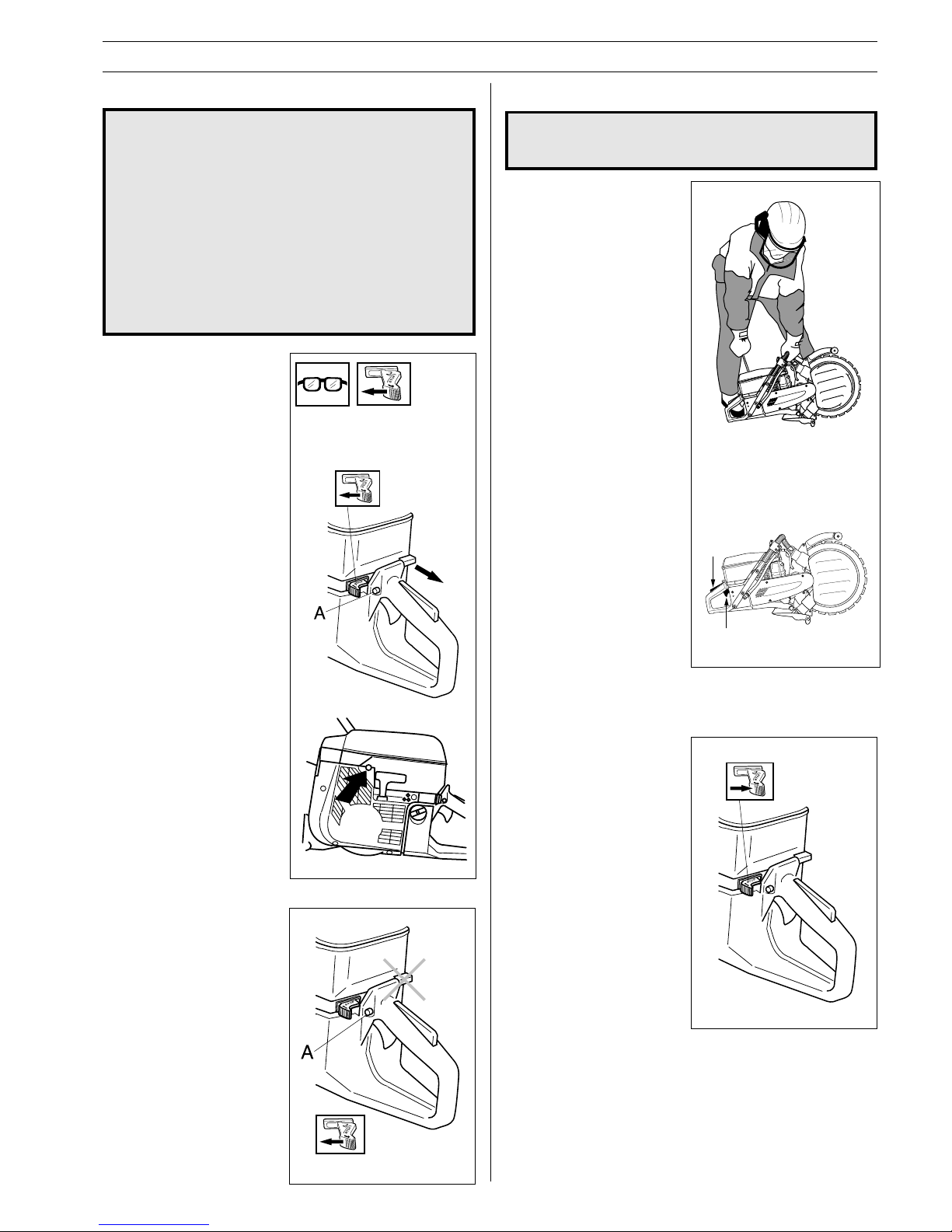
Starting a cold engine
IGNITION:
Slide the stop switch to the
left.
CHOKE:
Pull out the choke.
STARTER THROTTLE
CATCH
Press in the throttle control
and thereafter the starter
throttle catch (A). Release the
throttle control and the throttle
is blocked in half throttle
position. The catch is released
when the throttle control is
pressed in all the way.
DECOMPRESSION VALVE
Press in the valve to reduce
the pressure in the cylinder,
this makes starting the power
cutter easier. The
decompression valve should
always be used when starting.
When the machine has
started the valve automatically
returns to its original position.
Start and stop
WARNING! Before starting observe the
following:
• Do not start the power cutter without the
cutting arm or cutting head fitted. Otherwise
the clutch can come loose and cause perso
nal injury.
• Always move the power cutter from the
filling area before starting.
• Ensure that you and the machine stand
firmly and that the cutting blade rotates
freely.
• Make sure no unauthorised persons are
within the working area.
!
START AND STOP
Start
Take hold of the front handle
using your left hand. Place
your right foot on the lower
section of the rear handle and
press the power cutter against
the ground. Never twist the
starter cord around your
hand.
Grip the starter with your right
hand, and slowly pull the
starter cord out until you feel
some resistance (the pawls
grip) now pull quickly and
powerfully.
NOTE! Do not pull out the
starter cord completely and do
not release the starter from
the fully extended position.
This can damage the power
cutter.
When the engine starts,
quickly apply full throttle and
the starter throttle catch will
automatically disengage.
WARNING! The cutting blade can rotate when
the engine starts. Make sure it can rotate
freely.
!
Stop
The engine is stopped by
switching off the ignition.
(Slide the stop switch to the
right.)
Starting a warm
engine
Use the same procedure as
for starting cold engine but
without choke.
Page 18
18 – English
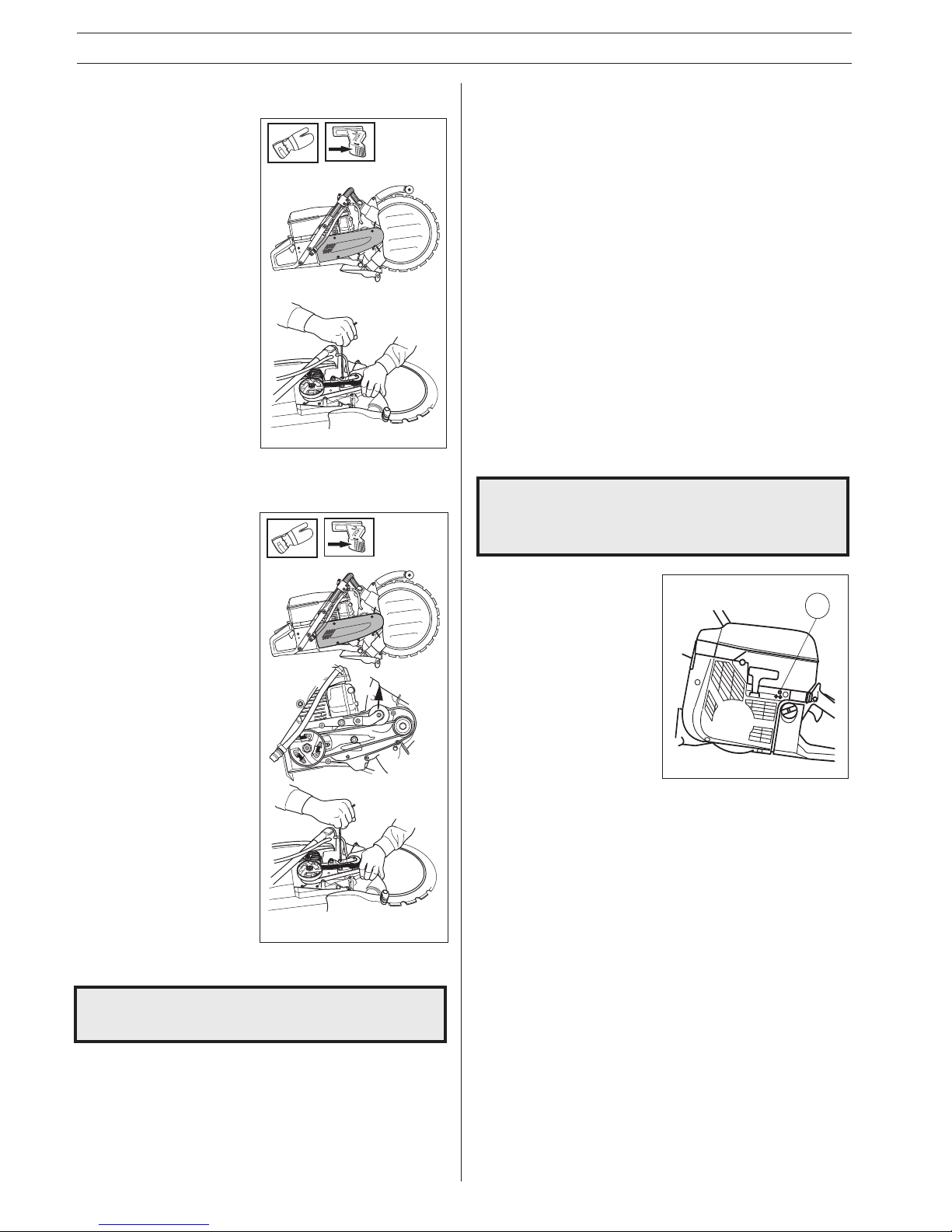
Adjusting the drive belt
• The drive belt is fully
enclosed and well protected
from dust, dirt and
mechanical effects during
the cutting process.
• To tension the drive belt,
remove the belt cover and
loosen the belt tensioner
bolt slightly, then apply firm
thumb pressure on the
tension roller and tighten
the tensioner bolt.
MAINTENANCE
!
Belt tensioning/changing the drive
belt
• Remove the belt cover and
loosen the belt tensioner
bolt slightly. Push back the
tension roller and install the
new belt.
Note: Make sure that the two
belt pulleys are clean before
installing a new belt.
• Apply firm thumb pressure
on the tension roller and
tighten the tensioner bolt.
• To assemble reverse the
procedure for dismantling.
WARNING! Never use a power cutter without a
blade guard over the cutting blade.
Belt pulley and clutch
Never start the engine when the belt pulley and clutch are
remove for maintenance.
Jets
The carburetor is equipped with fixed jets to ensure the engine
always receives the correct fuel air mixture.
If the engine lacks power or accelerates poorly do the following:
• Inspect or, if necessary, replace the air filter.
• If this does not help, contact an authorised service workshop.
Carburetor
Your Partner product has been designed and manufactured to
specifications that reduce harmful emissions.
T
Contact your servicing dealer, if the idle speed
setting cannot be adjusted so that the blade
stops. Do not use the power cutter until it has
been properly adjusted or repaired.
!
Final setting of the idling speed T
Adjust the idling speed with the screw T. If it is necessary to readjust, first turn the idle speed adjusting screw T clockwise, until
the blade starts to rotate. Then turn, counter-clockwise until the
blade stops. A correctly adjusted idle speed setting occurs
when the engine runs smoothly in every position. It should also
be good margin to the rpm when the blade starts to rotate.
Recommended idling speed: 2 500 rpm.
Page 19
English – 19
MAINTENANCE
Fuel filter
• The fuel filter sits inside the fuel tank.
• The fuel tank must be protected from contamination when
filling. This reduces the risk of operating disturbances caused
by blockage of the fuel filter.
• The filter cannot be cleaned but must be replaced with a new
filter when it blocked. The filter should be changed at least
once per year.
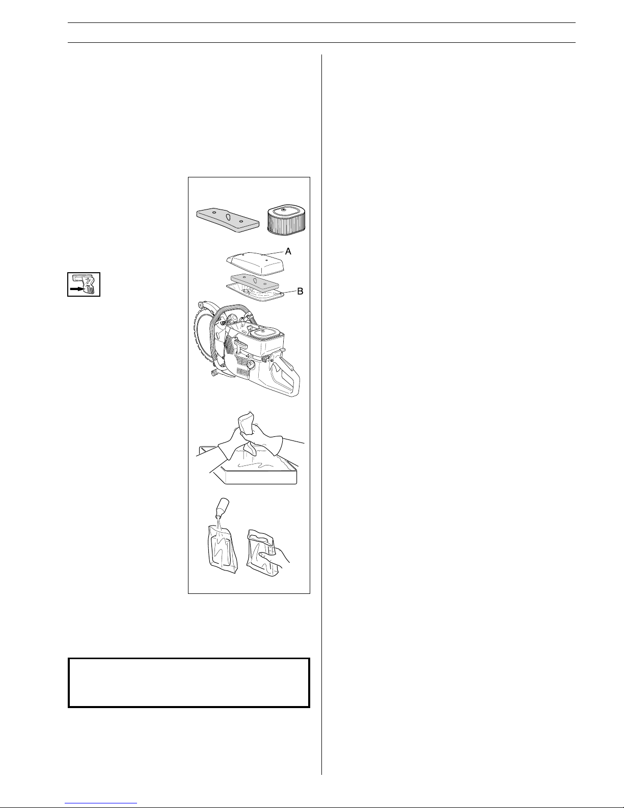
Air filter
The air filter should be
cleaned regularly removing
dust and dirt to avoid:
• Carburettor malfunction
• Starting problems
• Reduced engine power
• Unnecessary wear to
engine parts
• Abnormal fuel consumption
The air filter system consists
of an oiled main foam filter
and a paper filter:
1)The foam filter is easily
accessible under the filter
cover A. This filter shall be
checked once a week and
replaced when needed.
• The filter must be replaced
or cleaned and oiled
regularly to obtain a
satisfactory filtering effect.
Use a Partner Foam filter
oil for re-oiling.
• Remove the filter. Wash the
filter carefully in tepid,
soapy water. After cleaning
rinse the filter thoroughly in
clean water. Squeeze out
the filter and let the filter
dry. NOTE! Compressed air
at a high pressure can
damage the foam.
• Oil the filter carefully. It is
extremely important that
the entire filter is saturated
in oil.
2)The paper filter is accessible from under cover B. This filter
shall be checked once a week and replaced when needed.
The paper filter cannot be cleaned and must not be washed.
IMPORTANT INFORMATION!
Insufficient care of the air filter will cause deposits on
the spark plug resulting in abnormal wear to engine
parts.
2
1
Page 20
20 – English
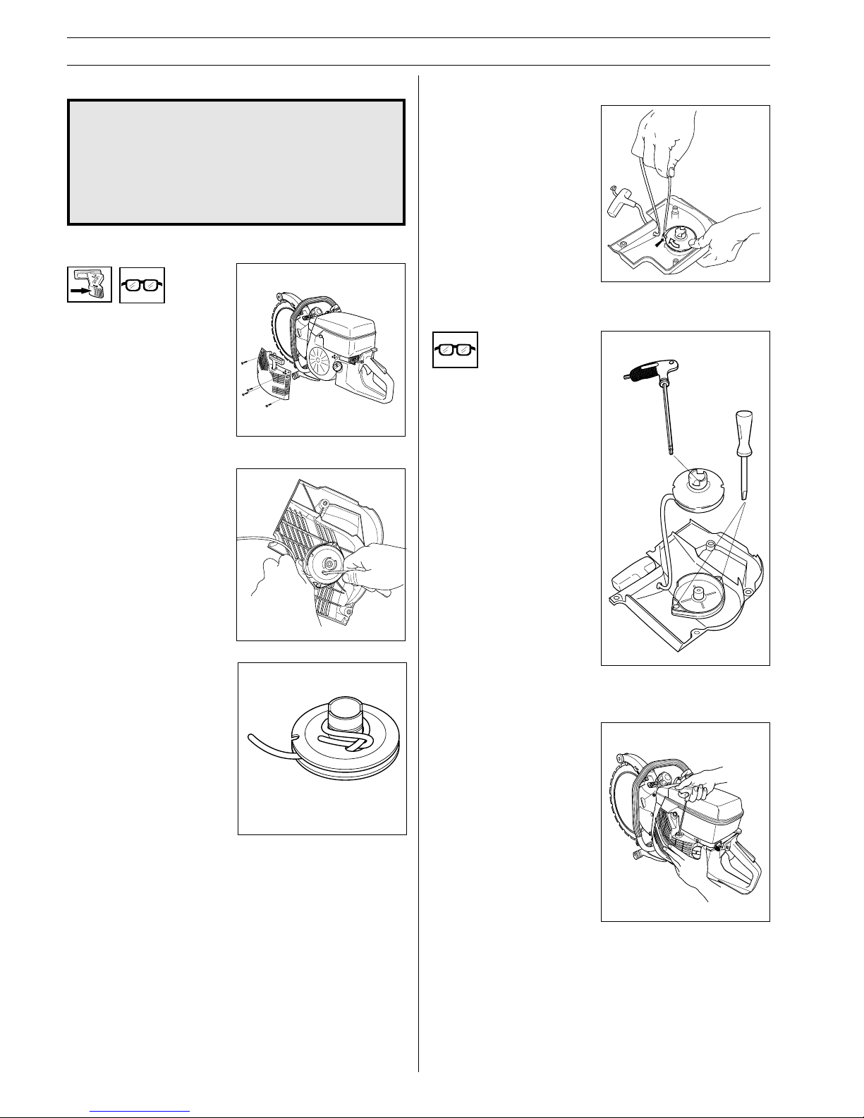
Replacing a broken or worn starter cord
• Loosen the bolts that hold
the starter against the
crankcase and lift off the
starter unit.
• Remove any remaining rope
from the pulley and check
that the return spring
recoils. Insert the new
starter rope through the
pulley.
• Anchor the rope around the
hub on the pulley as shown
on the illustration. Pull the
rope tight and make sure
that the free end is as short
as possible.
!
Tensioning the recoil spring
• Lift up the starter cord from
the cut out on the pulley and
turn the pulley approx.
7 turns clockwise.
NOTE! Ensure the starter
pulley can be turned at least
a further 1/2 turn when the
starter cord is fully
extended.
Replacing a broken recoil spring
• Lift the starter pulley (see
"Changing a broken or worn
starter cord"
).
• Loosen the screws holding
the spring cassette.
• Disassemble the recoil
spring by tapping the pully
(with its inside facing down)
lightly against a working
bench or similar. If the
spring pops out when
assembling, it should be
mounted again, out and in
towards the centre.
• Lubricate the recoil spring
with thin oil. Assemble the
starter pulley, and tension
the recoil spring.
Starter
WARNING!
• The recoil spring sits in its tensioned posi
tion in the starter housing and can with
careless handling fly out and cause personal
injury.
• When replacing the recoil spring or the
starter cord great care should be exercised.
Always wear protective glasses.
MAINTENANCE
Fitting the starter
• Fit the starter by first pulling
out the starter cord and then
placing the starter in
position on the crankcase.
No slowly release the
starter cord so that the
pawls grip in the pulley.
• Fit and tighten the screws
that hold the starter.
Page 21
English – 21
MAINTENANCE
Cooling system
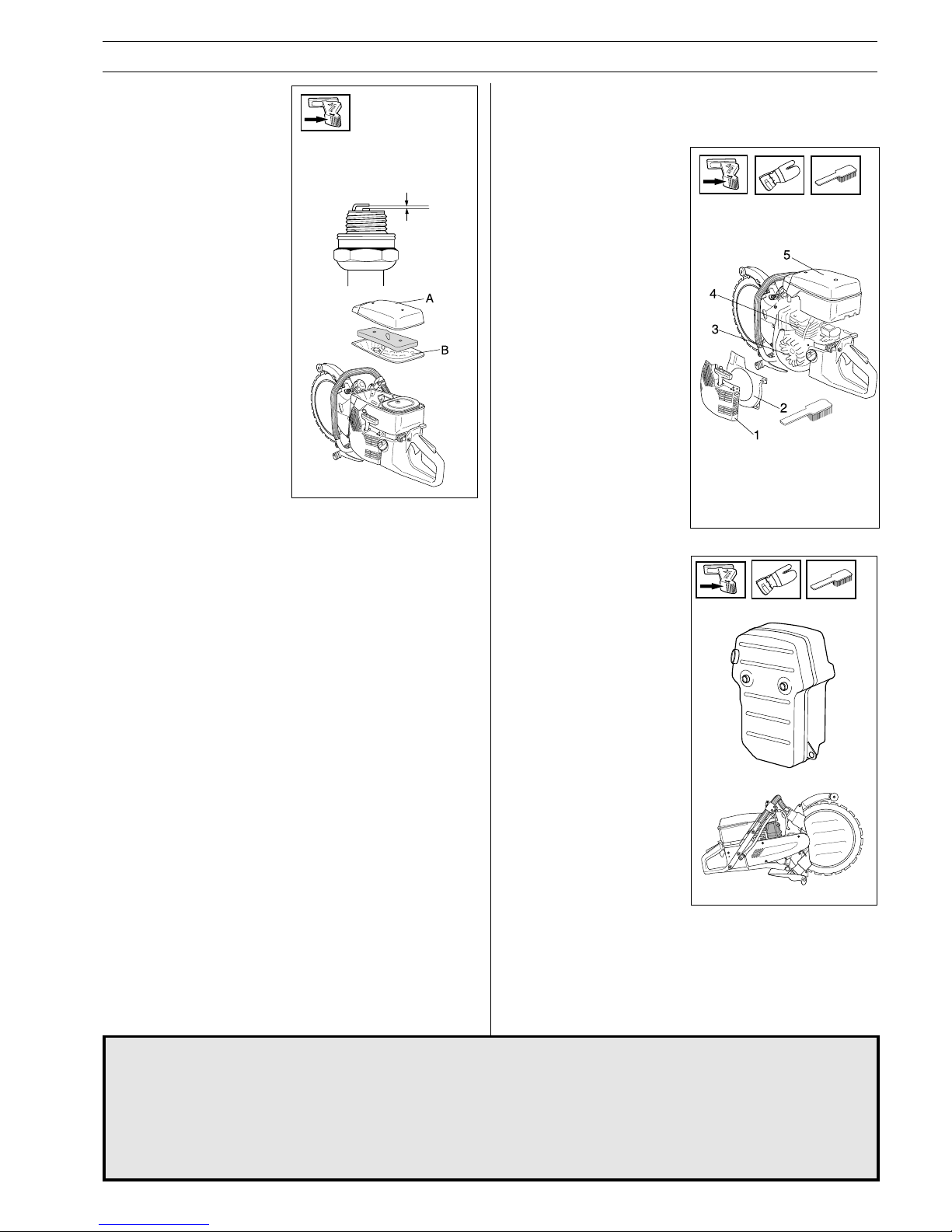
To maintain as low an operating temperature as possible the
power cutter is equipped with a cooling system.
The cooling system consists of:
1. An air intake on the
starter unit.
2. Air flow guide.
3. Cooling fins on the
flywheel.
4. Cooling fins on the
cylinder
5. Cylinder cover (leads cold
air onto the cylinder).
Clean the cooling system
using a brush at least once
a week, in difficult
conditions more often. A
dirty or blocked cooling
system leads to the engine
overheating resulting in
damage to the cylinder and
piston.
Muffler
The muffler is designed in
order to reduce the noise level
and to direct the exhaust
gases away from the operator. The exhaust gases are
hot and can contain sparks,
which may cause fire if
directed against dry and
combustible material.
Never use a saw with a
clogged or defective muffler.
Spark plug
The condition of the spark plug
is affected by:
• An incorrect carburetor
setting.
• An incorrect fuel mixture
(too much oil).
• A dirty air filter.
These factors cause deposits
on the spark plug electrode
that may result in malfunction
or starting difficulties.
• If the machine is low on
power, difficult to start or
runs poorly while idling
always check the spark
plug first. If the spark plug
is dirty, clean it and at the
same time check that the
electrode gap is 0,5 mm
(.020"). The spark plug
should be changed after
about one month of
operation or earlier if
necessary.
NOTE! Always use the recommended type of spark plug. (see
chapter
”Technical data”
)! An incorrect spark plug can damage
the cylinder/piston.
0,5 mm
Blade Retipping
!
WARNING! Do not retip ring blades. Because of its design, a ring blade is exposed to different stresses than
a center driven 14 inch diamond blade. First, the drive disc works on the inner diameter of the blade so that
both the drive disc and the blade surface wear. The blade core becomes thinner and the guide becomes
wider which prevents the blade from being driven by the disc. Secondly, the blade is exposed to stress from
the rollers and from the cutting itself, if the blade is not kept perfectly straight. Stress builds up in the blade,
until it may crack or even break if it is totally retipped. A broken blade may cause serious personal injury to
the operator or others. For this reason, Partner will not authorize a ring blade to be totally retipped. A single
segment may sometimes be retipped. Please contact your Partner dealer for instructions.
Page 22
22 – English
MAINTENANCE
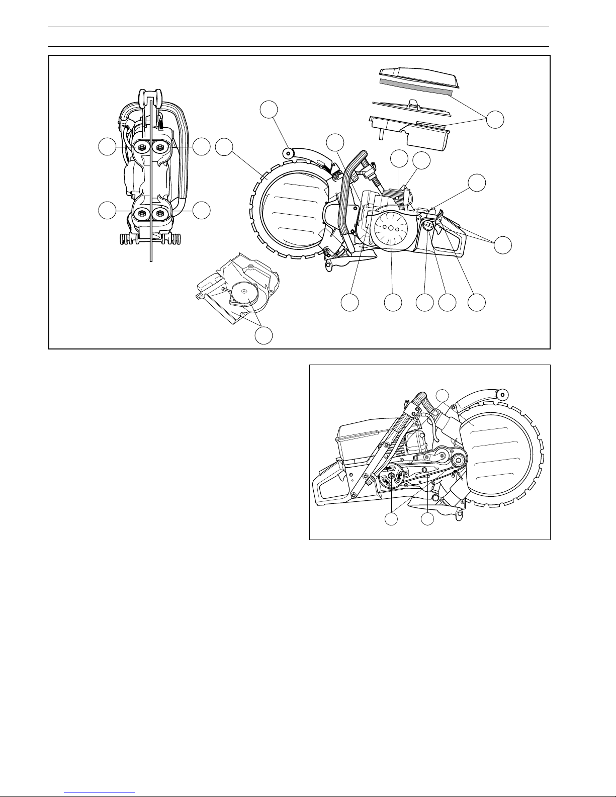
Below follows some general maintenance instructions.
If you need further information please contact your service
workshop.
Weekly maintenance
9. Check and clean the main filter.
10. Check the tension of the drive belt.
11. Clean the spark plug. Check that the electrode gap is 0.5
mm.
12. Clean the cooling fins on the flywheel. Check the starter
and recoil spring.
13. Clean the cooling fins on the cylinder.
14. Check the muffler.
15. Check and clean waterdisc and water inlet screen.
Monthly maintenance
16. Check the clutch drum, drive-pulley, and clutch springs with
regard to wear.
17. Clean the outside of the carburetor
18. Check the fuel filter, fuel hose, change if necessary.
19. Clean the inside of the fuel tank.
20. Check all cables and connections.
Daily maintenance
1. Check that throttle components work correctly from a safety
view point (throttle and starter throttle catch).
2. Check engagement roller wear daily.
3. Check support roller for wear twice a week.
4. Check the condition of the cutting blade and drive disc.
5. Check the condition of the bladeguard.
6. Check the starter and the starter cord; clean the outside of
the starter’s air intake.
7. Check that all nuts and bolts are tightened correctly.
8. Check the function of the stop switch.
16
10
15
3
3
2
2
4
11
13
9
14
17
1
8
191812
20
5
6
Page 23

English – 23
TECHNICAL DATA
Blade Diameter 350 mm (14")
Cutting Depth 260 mm (10")
Motor Speed, maximum 10 100 rpm
Weight, Cutting Blade 0,8 kg (1,8 lbs)
Dimensions: Height 410 mm (16")
Length 715 mm (28")
Width 260 mm (10")
Water Requirement 4 lit/min (1 gallon/min)
Cutting equipment
Cutting blade Max. peripherical speed
14" (350 mm) 55 m/s
Engine
Cylinder volume, cm3/cu.in 93,6/5,7
Cylinder bore, mm/inch ∅ 56/2,2"
Stroke, mm/inch 38/1,5"
Idle speed, rpm 2 500 rpm
Recommended max.
speed, unloaded, rpm 9 800 ± 300
Power, kW 4,5
Ignition system
Manufacturer FHP
Type of ignition system CD
Spark plug Champion RCJ-7Y
Electrode gap, mm/inch 0,5 (.020")
Fuel and lubrication system
Manufacturer Tillotson
Carburetor type HS 282A
Fuel capacity, litre/US Pint 1,0/2,65
Weight
Without fuel and cutting blade, kg/Lbs 13,1 kg/28.9 Lbs
Noise emissions
(see note 1)
Sound power level, measured dB(A) 117
Sound power level, guaranteed L
WA
dB(A) 118
Sound levels
(see note 2)
Equivalent sound pressure level at
the user’s ear, measured according to EN 1454 , dB(A). 103,5
Vibration levels
Handle vibrations measured according to EN 1454 m/s2.
Front handle, idling, m/s
2
7,7
Front handle, full speed, m/s
2
2,8
Rear handle, idling, m/s
2
11,8
Rear handle, full speed, m/s
2
7,5
Note 1: Noise emissions in the environment measured as sound power (L
WA
) in conformity with EC directive 2000/14/EC.
Note 2: Equivalent sound pressure level is calculated as the time-weighted energy total for sound pressure levels under various
working conditions with the following time distribution: 1/2 idling and 1/2 max speed.
K950 Ring
Page 24

24 – English
TECHNICAL DATA
1. Roller knobs not locked into position.
2. Blade not installed correctly on the engagement rollers.
3. Faulty bearing on rollers.
4. Rollers adjusted too tight.
1. Roller handles not locked into position.
2. Drive disc worn.
3. Inner edge of blade worn.
4. Springs on engagement rollers weakened.
5. Faulty bearing on rollers.
1. Roller adjustment too loose.
2. Worn engagement rollers.
3. Blade not installed on engagement rollers correctly.
4. Damaged blade.
1. Rollers adjusted too tight.
2. Blade overheating.
1. Blade bent, twisted, or abused.
2. Improper weld. Continue to use blade if only one segment is lost or return to have
it retipped if blade is not worn more than 50 percent.
1. Wrong blade for material.
1. Engagement roller not moving freely in and out. A stuck roller cannot push the
blade hard enough against the drive disc.
2. Drive disc worn. Abrasive material and poor flushing will wear the disc faster.
3. Engagement roller shoulder worn. If the width of the shoulder is more than 50%
worn, the blade will slip.
4. Blade tracking groove and inner edge worn. Caused by poor flushing of abrasive
material and/or a worn drive disc which causes the blade to slip.
A. Blade will not rotate.
PROBABLE CAUSESSYMPTOM
Troubleshooting
B. Blade turning too slow.
C. Blade jumps off.
D. Blade warped.
E. Segment loss.
F. Blade cutting too
slowly.
G. Blade slips.
EC declaration of conformity (Only applies to Europe)
Partner Industrial Products, SE-433 81 Partille, Sweden, tel. +46-31-949000, declare under sole responsibility that the power
cutter Partner K950 Ring from the serial numbers of 2002 and onwards (the year is clearly stated in plain text on the type plate
with subsequent serial number), are in conformity with the following standards or other normative documents following the
provisions in the COUNCIL’S DIRECTIVES:
- of June 22 1998 “relating to machinery” 98/37/EC, Annex IIA.
- of May 3 1989 “relating to electromagnetic compatibility” 89/336/EEC, and applicable supplements.
- of May 8 2000 "relating to noise emission, see "TECHNICAL DATA".
For information relating to the noise emission, see "TECHNICAL DATA":
The following standards have been applied: EN292-2, CISPR 12:1997, EN1454.
SMP Svensk Maskinprovning AB, Fyrisborgsgatan 3, SE-754 50 Uppsala, Sweden, has carried out voluntary type approval
for Husqvarna AB. The certificate is numbered: 01/169/011 - K950 Ring.
Partille October 1, 2002
Ove Donnerdal, Development manager.
Mechanical
Page 25

Page 26

´®z*xw@¶6&¨
Page 27

English – 27
Page 28

´®z*xw@¶6&¨
2003W06
108 88 73-26
 Loading...