

Page 1

P
R
AR
T
NER
Wor
M
a
k
shop
nu
a
l
Page 2

Workshop Manual
Petrol power cutters
Contents
General recommendations .................................................. 2
1. Starter unit ......................................................................... 3
2. Ignition system ............................................................... 11
3. Fuel system ..................................................................... 19
4. Centrifugal clutch ........................................................... 41
5. Cylinder and piston ........................................................ 47
6. Crankshaft and crankcase ............................................. 59
7. Cutting equipment .......................................................... 77
8. Tools................................................................................. 85
9. Technical data ................................................................. 93
This manual covers models:
K 650/700 Active
K 950/1250 Active
©
Copyright Partner Industrial Products, Sweden
1
Page 3

General recommendations
Keep this in mind:
Do not start the engine unless the clutch and clutch drum
!
are fitted.
!
Do not touch hot parts, e.g. silencer and clutch, before they
have cooled sufficiently to avoid burn injuries.
!
Avoid getting petrol or oil on the skin or in the mouth. Use
protective cream on the hands. This reduces the risk of
infection and makes it easier to wash off dirt. Prolonged
exposure to engine oil can be hazardous to health.
!
Never start the engine indoors. The exhaust fumes are
toxic!.
Wipe up spilled oil immediately from the floor to avoid
!
slipping.
!
Do not use tools which are worn or have a poor fit, e.g. nuts
and screws.
+Always work on a clean work bench.
+Always work in a logical way to make sure that all parts are
correctly fitted and that screws and nuts are tightened.
+Use special tools where so recommended in order to do the
work correctly.
Fire hazard
Handle petrol with respect since it is highly inflammable.
Do not smoke, and make sure that there are no naked flames or
sparks in the vicinity.
Make sure that there is a functioning fire extinguisher in the
vicinity.
Do not try to extinguish a petrol fire with water.
Use an anti-spill fuel can.
Special tools
Some work procedures in this Workshop Manual require the
use of special tools. In each section where this is appropriate
the tool and order number are illustrated.
We recommend the use of special tools partly to avoid personal
injury and partly to eliminate expensive damage to the
components in question.
Sealing surfaces and gaskets
Make sure that all sealing surfaces are clean and free from the
residue of old gaskets. Use a tool which will not damage the
sealing surface when cleaning it. Scratches and irregularities
are removed with a fine, float cut file.
Sealing rings
Always replace a sealing ring which has been dismantled. The
sensitive sealing lip can easily be damaged and result in poor
sealing capacity. The surface which the seal seals must also be
completely undamaged. Lubricate the sealing lip with grease
before it is fitted and make sure that it is not damaged, e.g. by
the shoulder and splines on a shaft. Use tape or a conical
sleeve as protection. It is important that the sealing ring is
correctly turned for it to function as intended.
Toxic fumes
Read the instructions carefully when using cleaning liquids.
Make sure that there is adequate ventilation when handling petrol
and other viscous liquids.
The engine exhaust fumes are toxic. Test run the engine outdoors.
!
WA RN I NG
The engine exhaust from this product
contains chemicals known to the State
of California to cause cancer, birth
defects or other reproductive harm.
2
Page 4
Starter unit
1.
1
Contents
Dismantling of the starter unit ..............................................4
Replacing the starter cord without dismantling the pulley ... 5
Dismantling ...........................................................................7
Assembly .............................................................................. 8
3
Page 5
1
Starter unit
!
WARNING!
When working on the starter unit wear protective glasses to avoid eye injuries in the
event that the return spring flies out.
Dismantling of the
starter unit
Mod. 650, 700
Dismantle the air filter cover, intermediate
wall and cylinder cover.
A
Dismantle the starter unit from the engine
body.
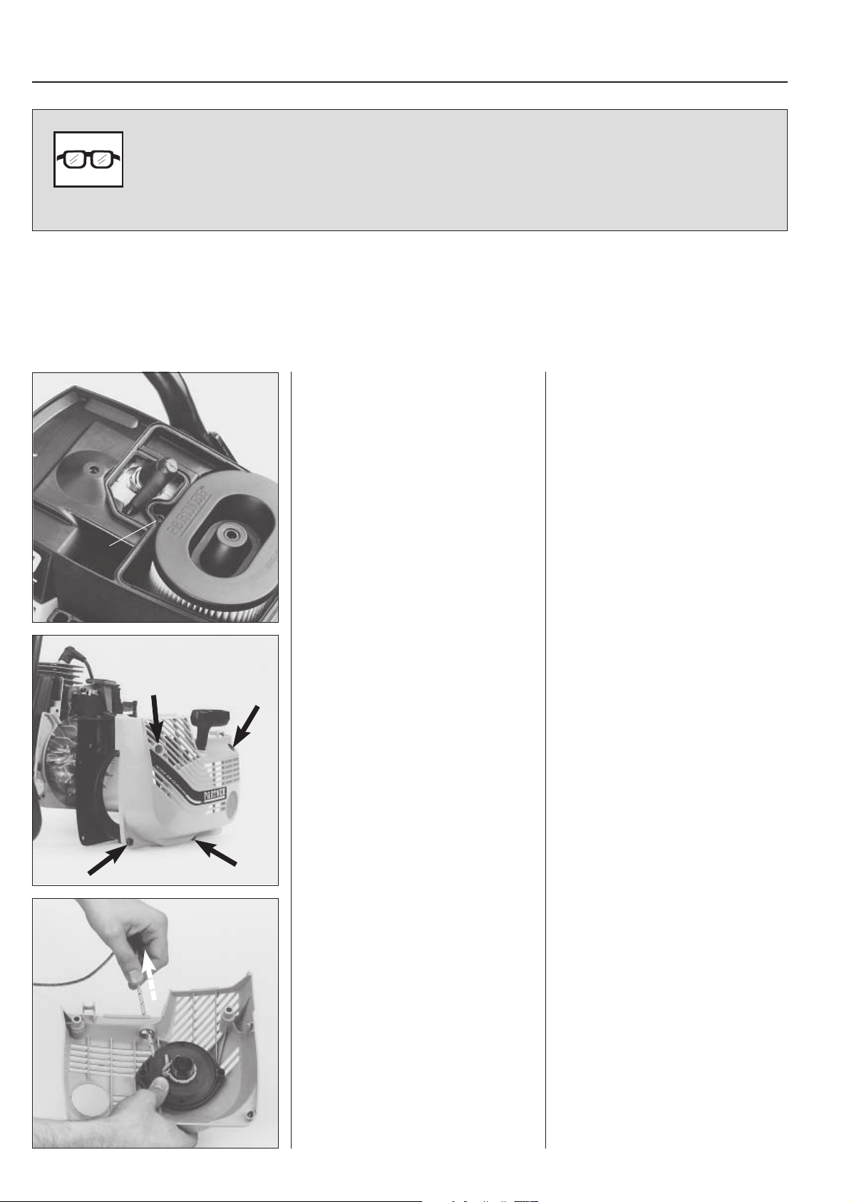
Dismantling of the
starter unit
Mod. 650, 700
Untighten the screws for the air filter
cover.
Lift off the cover and intermediate wall.
Release the screw (A) and lift off the
cylinder cover.
Untighten all the screws and lift off the
starter unit.
Release the spring tension.
4
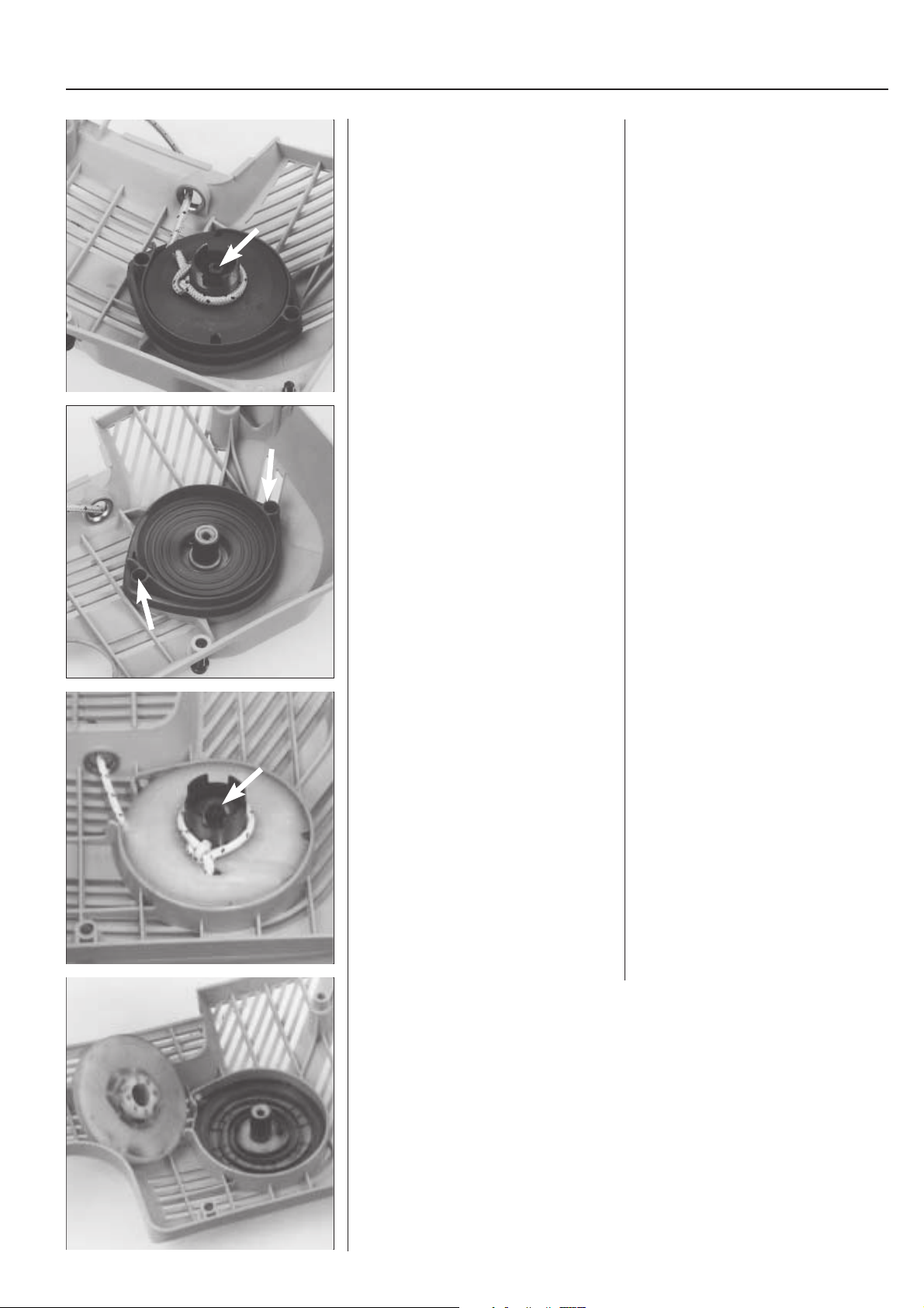
Release the spring tension.
Pull out the starter rope approx. 30 cm
(12 in).
Hold the pulley with your thumb and place
the cord in one of the recesses in the
pulley.
Page 6
Starter unit
1
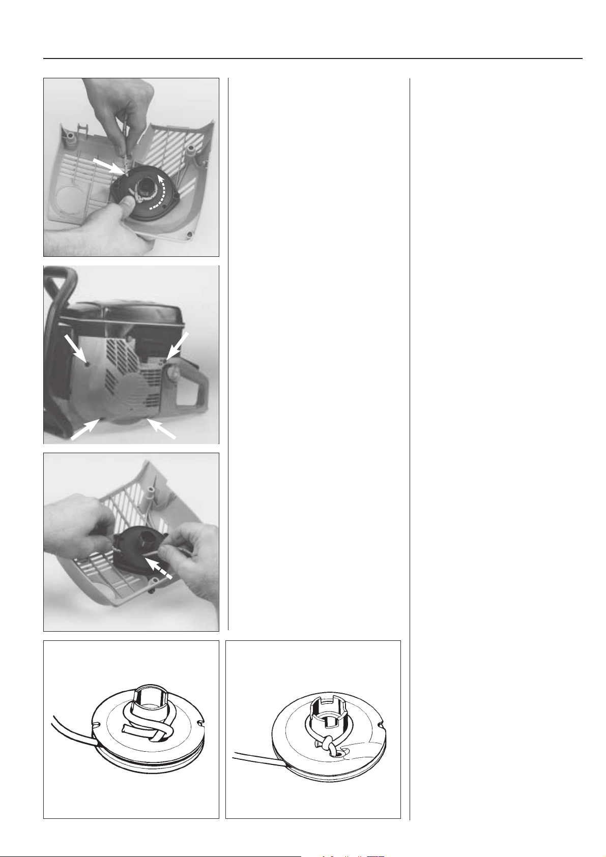
Allow the pulley to slowly rotate backwards.
Remove the starter handle.
Mod. 950, 1250
Remove the screws which hold the starter unit, and lift off the starter unit.
The next stage in the dismantling work
follows mod. 650/700.
Allow the pulley to slowly rotate backwards.
NOTE!
Brake the rotation with the thumb.
Untie the knot on the starter rope and
remove the starter handle.
Tips!
The knot may be difficult to untie. It is
easier if it first is tapped with a hammer
while placed on a hard surface.
Mod. 950, 1250
Remove the screws which hold the starter unit, and lift off the starter unit.
NOTE!
The air filter and cylinder covers do not
need to be dismantled.
The next stage in the dismantling work
follows mod. 650/700.
K650/700
K950
Replacing the starter
cord without dismantling the pulley
Mod. 650, 700, 950, 1250
Remove any remaining rope from the
pulley and check that the return spring
recoils.
Insert the new starter rope through the
hole in the pulley.
K1250
Replacing the starter
cord without dismantling the pulley
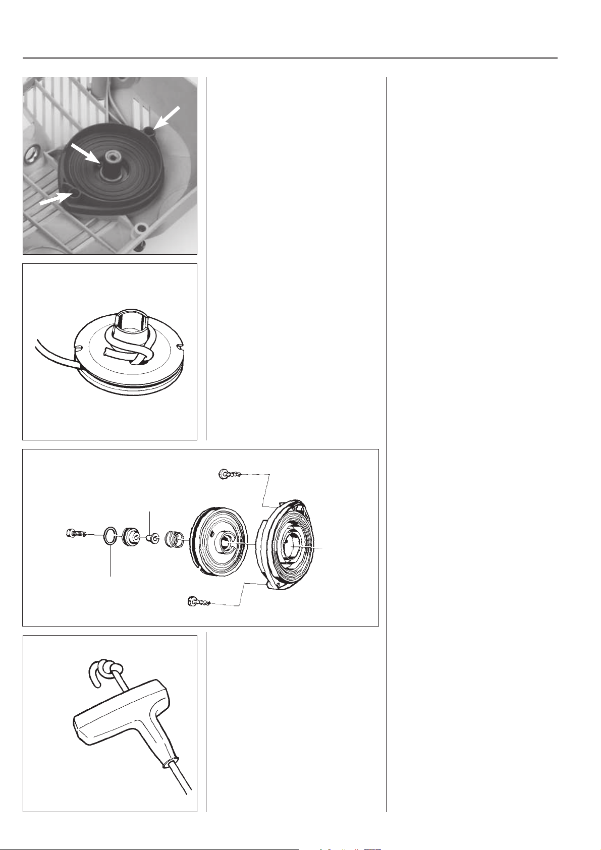
Mod. 650, 700, 950, 1250
Remove any remaining rope from the
pulley.
Check that the return spring and its
attachment in the pulley has not been
damaged by turning the pulley clockwise.
Enter the new starter rope through the
hole in the pulley as shown in the illustration.
Anchor the rope round the hub on the
pulley as shown in the illustration.
Pull the rope tight and make sure that the
free end is as short as possible.
Cord lengths
Models 650, 700, 950: 1150 mm.
Models 1250: 1250 mm.
These lengths apply to Ø 4 mm cord.
5
Page 7
1
Starter unit
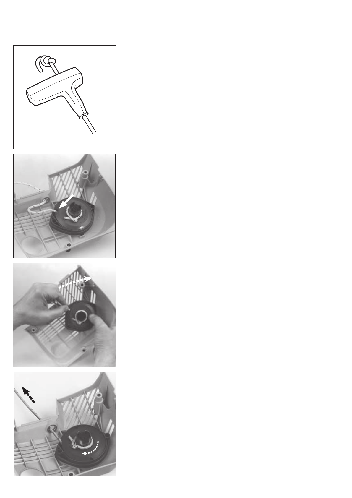
Anchor the starter rope in the starter
handle with a double knot.
Te ns i on the retur n spring.
Check that the spring tension is completely
released, and lift the starter cord up into
the cut-out in the pulley.
Insert the rope through the rope guide in
the starter housing and anchor it in the
starter handle with a double knot.
Te ns i on the retur n spring.
1. Check that spring tension is competely
released.
2. Lift the starter cord up into the cut-out
in the pulley.
Max
Wind the pulley 7 turns
Pull the cord out completely and check
that the pulley can be turned at least a
further half turn.
clockwise.
3. Wind the pulley 7 turns
Be careful and brake the pulley with
your thumb.
4. Pull the cord out completely and check
that the pulley can be turned at least
a further half turn.
clockwise.
+1/2
6
Page 8
Starter unit
1
Dismantling
Mod. 650, 700, 950
Remove the screw in the centre of the
pulley and lift off the pulley.
Dismantle the spring cassette.
WARNING!
!
The return spring in the spring cassette is pre-tensioned and can if not
handled carefully during dismantling/fitting fly out and cause personal injury.
Dismantling
Mod. 650, 700, 950
Remove the screw in the centre of the
pulley.
Lift off the pulley.
Remove the screws and lift off the spring
cassette.
WARNING!
!
The return spring in the spring cassette is pre-tensioned and can if not
handled carefully during dismantling/fitting fly out and cause personal injury.
Mod. 1250
Remove the screw in the centre of the
pulley and lift off the pulley.
Make sure that the return spring is
completely released, and dismantle the
pulley.
WARNING!
!
The return spring is
starter unit cover.
Observe care during dismantling/assembly, the spring can fly out and cause
personal injury.
not
placed in a separate cassette but i s p la ced directly in the
Mod. 1250
Remove the screw in the centre of the
pulley and lift off the pulley.
Make sure that the return spring is
completely released.
Remove the screw and washer in the
centre of the pulley.
Carefully lift off the pulley.
7
Page 9
1
Starter unit
Assembly
Mod. 650, 700, 950
Clean the starter unit components and fit
the spring cassette.
Anchor the cord in the pulley.
Push the pulley on the shaft stem.
Assembly
Mod. 650, 700, 950
Clean the different starter unit parts.
Lubricate the return spring with oil and
place the spring cassette in the starter
unit housing.
Make sure that the spring end is not
clenched.
Tighten the screws.
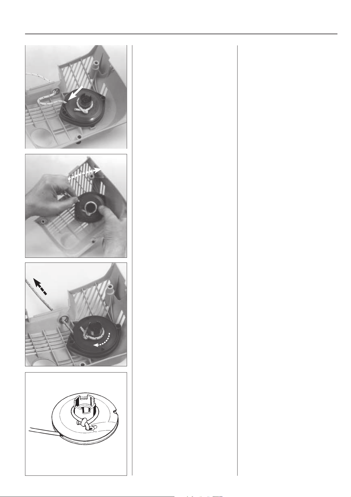
Anchor the cord round the pulley hub as
shown in the illustration.
Push the cord down on the shaft journal in
the starter unit housing.
Make sure that the return spring grips in
the pulley.
Lubricate the starter housing stem and
pulley with a few drops of oil.
Fit the other parts in the pulley hub.
NOTE!
Turn the metal sleeve (B) correctly.
B
C
Anchor the starter cord in the starter
handle with a double knot.
Check that the O-ring (C) is undamaged.
Lubricate it with a few drops of oil.
Tighten the centre screw and check that
the pulley can turn freely.
Enter the cord through the cord guide in
the starter unit and anchor it in the starter
handle with a double knot.
8
Page 10
Starter unit
1
Te ns i on the retur n spring.
Check that the spring tension is completely
released, and lift the starter cord up into
the cut-out in the pulley.
Wind the pulley 7 turns
clockwise.
Te ns i on the retur n spring.
1. Check that spring tension is competely
released.
2. Lift the starter cord up into the cut-out
in the pulley.
3. Wind the pulley 7 turns
Be careful and brake the pulley with
your thumb.
clockwise.
Max
+1/2
Pull the cord out completely and check
that the pulley can be turned at least a
further half turn.
Mod. 1250
Press a new return spring down in the
starter unit cover.
Lubricate the spring with a few drops of
oil.
Anchor the cord in the pulley.
Push the pulley down onto the shaft journal.
4. Pull the cord out completely and check
that the pulley can be turned at least
a further half turn.
Mod. 1250
Press down a new return spring in the
starter unit cover.
NOTE!
Do not remove the lock round the spring,
but push down the spring all round by
using your thumbs.
Lubricate the spring with a few drops of
oil.
Anchor the starter cord round the hub of
the pulley as shown in the diagram.
Push the cord wheel down on the shaft
journal in the starter unit housing.
Make sure that the spring grips the cord
wheel.
Lubricate the bearing with a few drops of
oil.
9
Page 11
1
Anchor the starter cord in the starter
handle with a double knot.
Fit the starter unit and other parts in the
reverse order to dismantling.
Enter the cord through the cord guide in
the starter unit and anchor it in the starter
handle with a double knot.
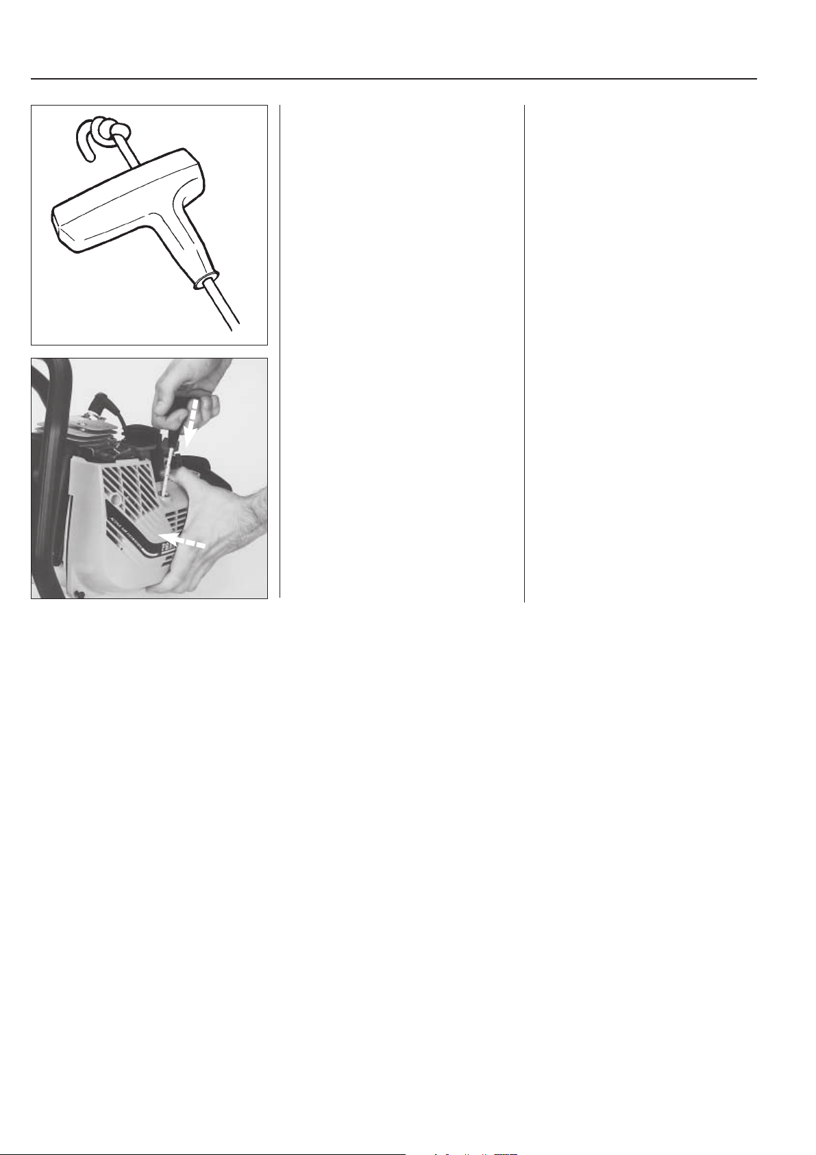
Fit the starter unit.
Pull out the starter cord a little. Place the
starter unit in position. Release the starter cord and check that the pawls engage
the pulley.
Tighten the screws.
10
Page 12
Ignition system
2.
2
Contents
The principle of the ignition system ............................ 12
Checking the ignition spark ........................................ 13
Replacing the spark plug protection ........................... 15
Dismantling ................................................................. 15
Starter pawls ............................................................... 17
Assembly .................................................................... 17
11
Page 13
2
Ignition system
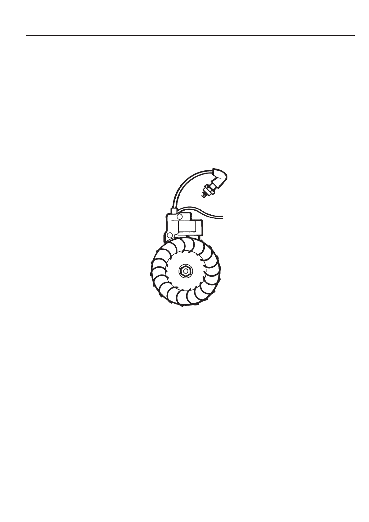
The engine is fitted with an electronic ignition system consisting of flywheel, ignition coil and trigger
unit.
The ignition system has no moving parts. A defective
component cannot be repaired but must be replaced
with a new one.
The ignition spark in an electronic ignition system
has a very short burn time and may therefore be
experienced as weak, and sometimes be dif ficult to
see during trouble shooting.
2
+
Volts
0
1
A
N
S
N
2
3
B
A
C
S
1
DBC
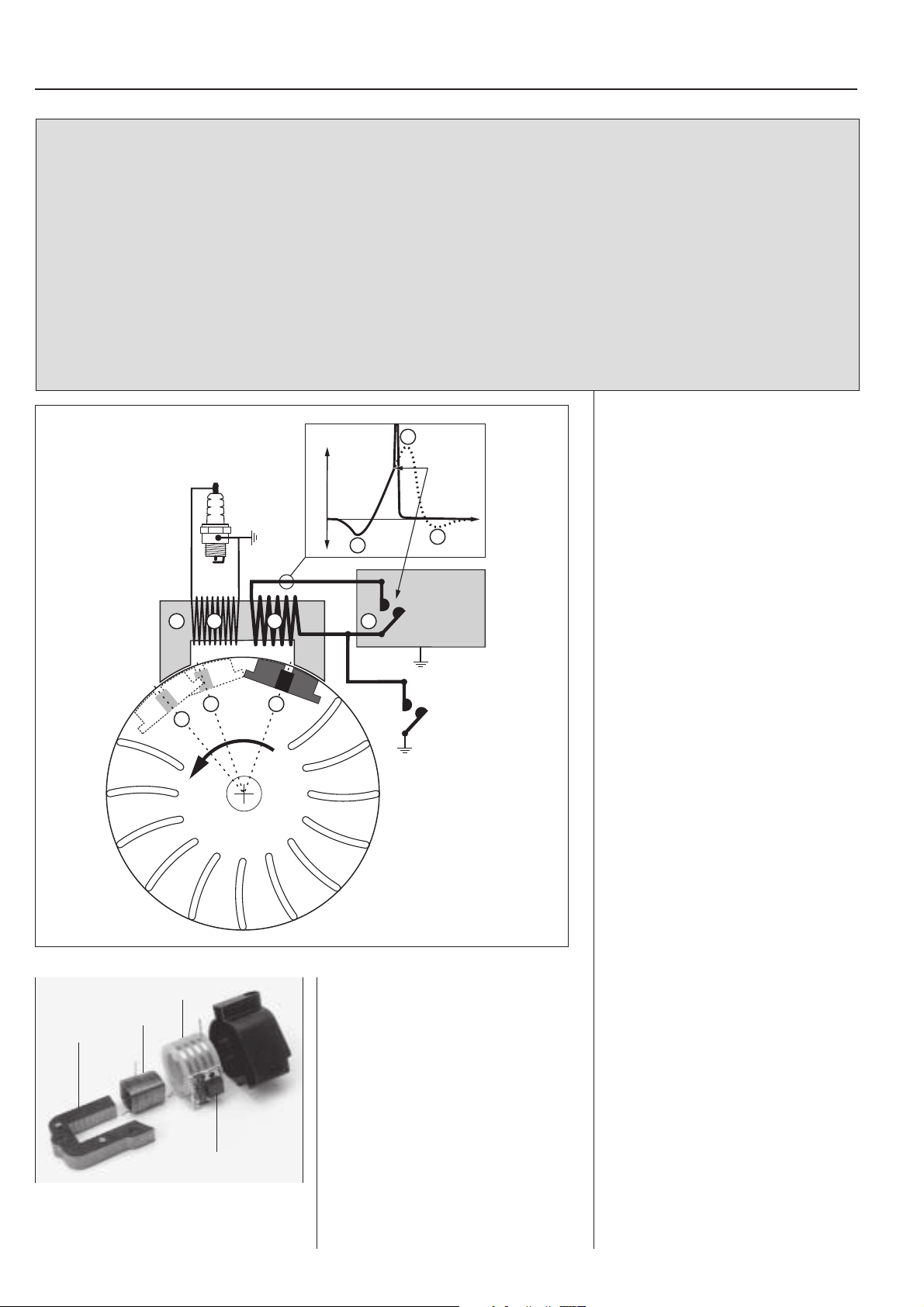
The ignition module components are
completely enclosed to protect them from
moisture and dirt.
In the event of a failure in the ignition
module it must be replaced with a new
one.
E
3
G
E = Ignition point
F = Trigger unit
G = Stop switch
NOTE!
During all test running of the cutting saw the
clutch and clutch cover must be fitted before the
engine is started!
Principle of the ignition
system
The ignition system is completely enclosed and no after-adjustment of the
ignition point is possible or necessary.
The ignition module is built up of an iron
core (C). Round this lies the primary coil
(A) which consists of a small number of
turns of thick copper wire. Outside this
lies the secondary coil (B) which has a
F
very large number of turns of copper
wire.
The trigger unit (F) is fitted on the
secondary coil and has the purpose of
breaking the current (D) in the primary
winding at exactly the right time, i.e. just
before the piston reaches the top dead
centre.
When the permanent magnet (1) on the
flywheel passes the ignition module’s
iron core, an electric current is generated
in the primary coil (A). At the breaking
moment the current in the primary coil
rises from 5 volts to approx. 200 volts by
means of induction.
In the secondary coil (B) a high voltage
(approx. 20 000 volts) is simultaneously
transformed to the spark plug.
Models K650,K700, K950 and K1250
have a built-in overspeeding protection
in the electronic unit which limits the
unloaded speed of the engine to about
9 750 rpm.
The ignition module components are
completely enclosed to protect them from
moisture and dirt.
In the event of a failure in the ignition
module it must be replaced with a new
one.
12
F
A = Primary coil
B = Secondary coil
C = Iron core
F = Trigger unit
Page 14
Ignition system
2
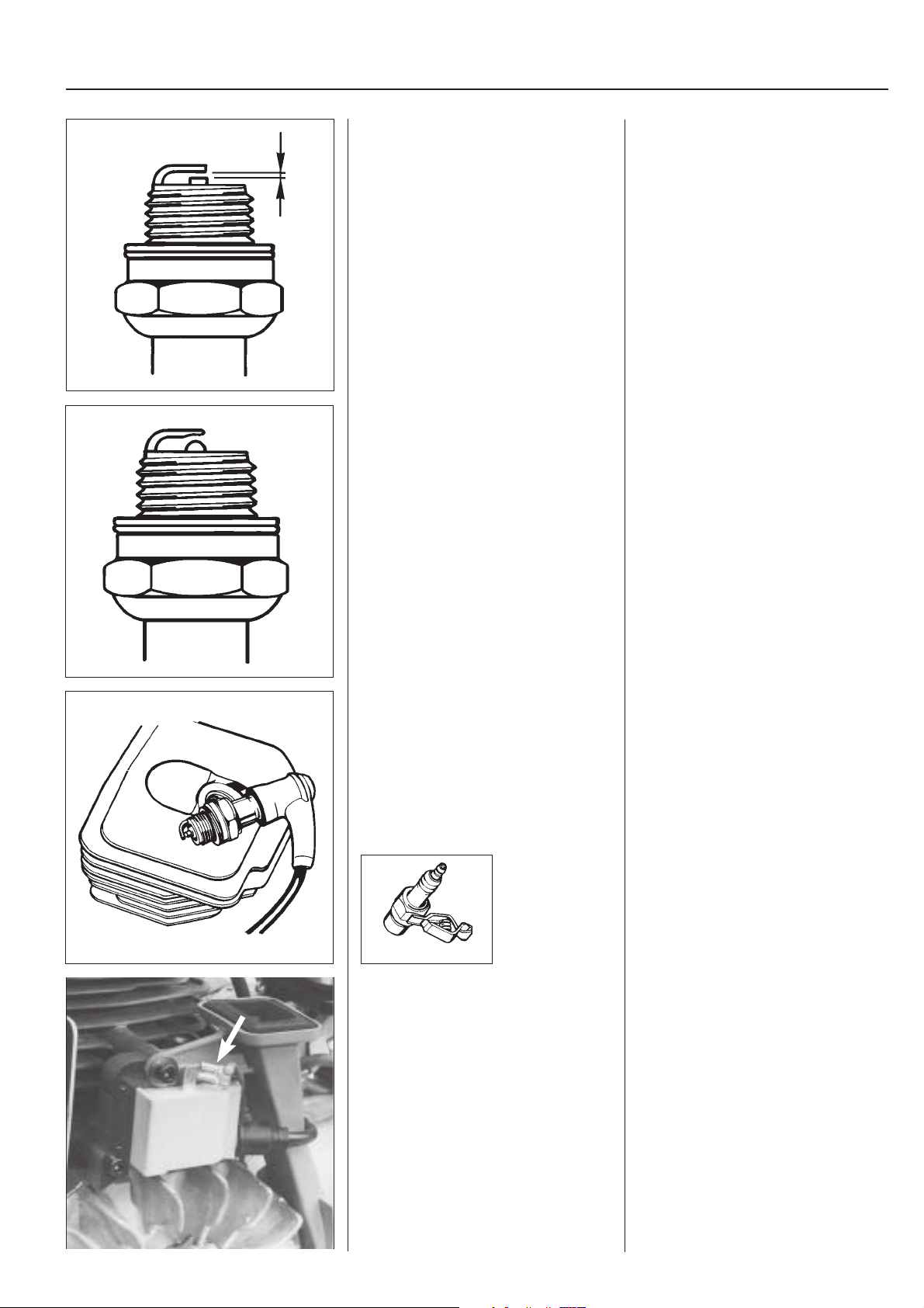
Checking ignition spark
Clean the electrodes and check the
electrode gap.
If the electrodes are worn down more
than 50% the plug should be replaced.
Checking ignition spark
Dismantle the plug and clean it from soot
by means of a wire brush.
Check the electrode gap. It should be 0.5
mm (.020 in).
Adjust the gap to the correct distance with
the side electrode.
If the electrodes are worn down more
than 50% the plug should be replaced.
If the gap is too wide this results in strain
on the ignition module and the risk of
short circuiting.
Check if there is a spark by pulling the
engine over with the starter.
Try with test plug No. 502 71 13-01 if
there is no spark.
502 71 13-01
Try with a new plug.
If there is no spark disconnect the stop
switch wire.
If necessary replace the switch.
Check if there is a spark by pulling the
engine over with the starter.
Ground the plug to the cylinder and briskly
pull the starter handle.
Make sure that the stop switch is in the
start position.
There should be a spark between the
electrodes.
If there is no spark try with test plug No.
502 71 13-01!
If there is a spark the fault lies in the plug.
Replace the plug.
Try with a new plug.
If there is still no spark remove the short
circuiting cable from either the ignition
module or the stop switch.
If there is now a spark the fault lies in the
stop switch.
Replace the switch.
13
Page 15
2
Ignition system
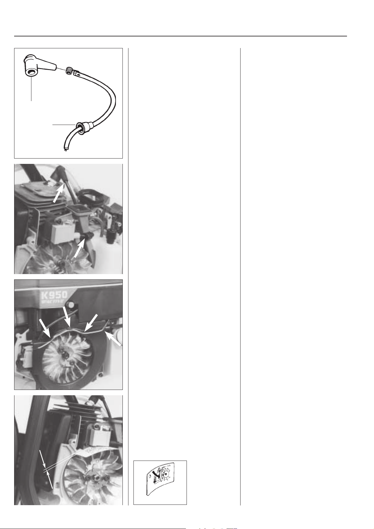
Check the ignition cable’s connections.
A
B
Grease the cable ends before fitting.
Still no spark?
Check the plug connection.
Pull off the rubber protection at the plug
(A) and ignition module (B) and check
that the ignition cable is undamaged. If
necessary cut off a piece of the cable to
ensure good contact.
Grease the cable ends to simplify fitting
and to prevent moisture penetrating into
the connections.
0,3 – 0,5 mm
Check the other cables and connections. Still no spark?
Check the other cables and connections
for poor contact (dirt, corrosion, cable
break and damaged insulation).
Tips!
Use an Ohm meter to check if there is a
cable break, e.g. as a result of pinching.
Check the air gap. Still no spark?
Check the air gap between the flywheel
magnet and ignition module. The gap
should be 0.3 – 0.5 mm (0.012–0.020").
Use air gap measure 502 51 34-06.
14
502 51 34-06
Page 16
Ignition system
2
Adjust the air gap.
502 51 34-06
Replacing spark plug
protection
1. Take the ignition cable through the
plug protection.
2. Fit the contact spiral on the ignition
cable.
Adjust where appropriate the air gap to
the correct distance.
• Release the screws holding the
ignition module.
• Position the feeler gauge on the
magnets of the flywheel and press the
ignition module against flywheel.
• Tighten the screws and check the air
gap again.
If there is still no spark then the ignition
system should be replaced.
Replacing spark plug
protection
1. Grease the ignition cable with a little
grease and take it through the plug
protection.
2. Cut off a piece of the ignition cable
(approx. 5 mm, 3/16") to obtain full
contact with the spark plug protection.
3. Fit the contact spiral on the ignition
cable and make sure that the wire is
folded along the cable.
4. Pull the contact spiral in the plug
protection.
NOTE!
It is important that the point on the contact
spiral meets the middle of the ignition
cable to prevent sparking.
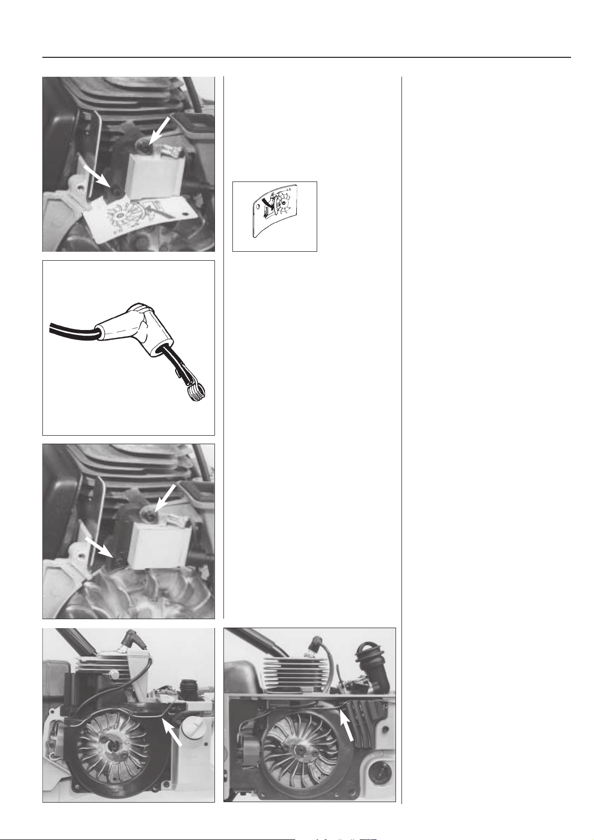
Dismantling
Mod. 650, 700
Dismantle the cylinder cover, plug, starter unit, and air conductor.
Dismantle the ignition module and release the other cable connections.
K 950 K 1250
Dismantling
Mod. 650, 700
Dismantle the plug, cylinder cover, starter unit, and air conductor.
Dismantle the ignition module by removing the two screws.
Release the other cable connections and
lift off the ignition module.
Mod. 950, 1250
Dismantle the starter unit, air filter cover,
air filter and cylinder cover.
Remove the air conductor.
Note the position of the cables so that
they can be replaced in the same way.
15
Page 17
2
Ignition system
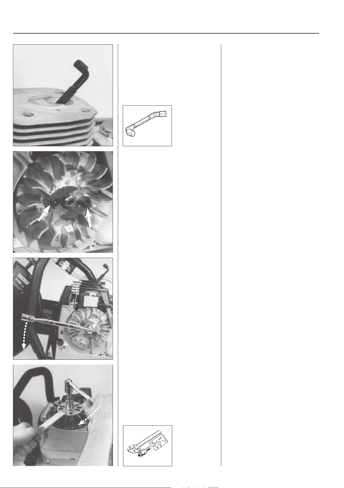
Fit piston stop No. 502 54 15-01 in the
spark plug hole.
502 54 15-01
Mod. 650, 700, 950, 1250
Dismantle the starter pawls.
Insert piston stop No. 502 54 15-01 in the
sparking plug hole.
Make sure that the piston stop does not
come out through the exhaust port, it
must rest against the front of the cylinder
wall when the piston approaches Top
Dead Centre.
Mod. 650, 700, 950, 1250
Dismantle the starter pawls by releasing
the screws. Make sure the small washer
which lies next to the flywheel is not lost.
Remove the flywheel nut. Remove the flywheel nut by means of a
suitable box spanner.
Pull off the flywheel. Remove the flywheel by means of fly-
wheel puller 502 51 49-02, which is
screwed tight in the holes for the pawls.
NOTE!
Centre the flywheel puller over the shaft
centre. Select suitable screws and tighten
the withdrawing tool.
16
502 51 49-02
Page 18
Ignition system
2
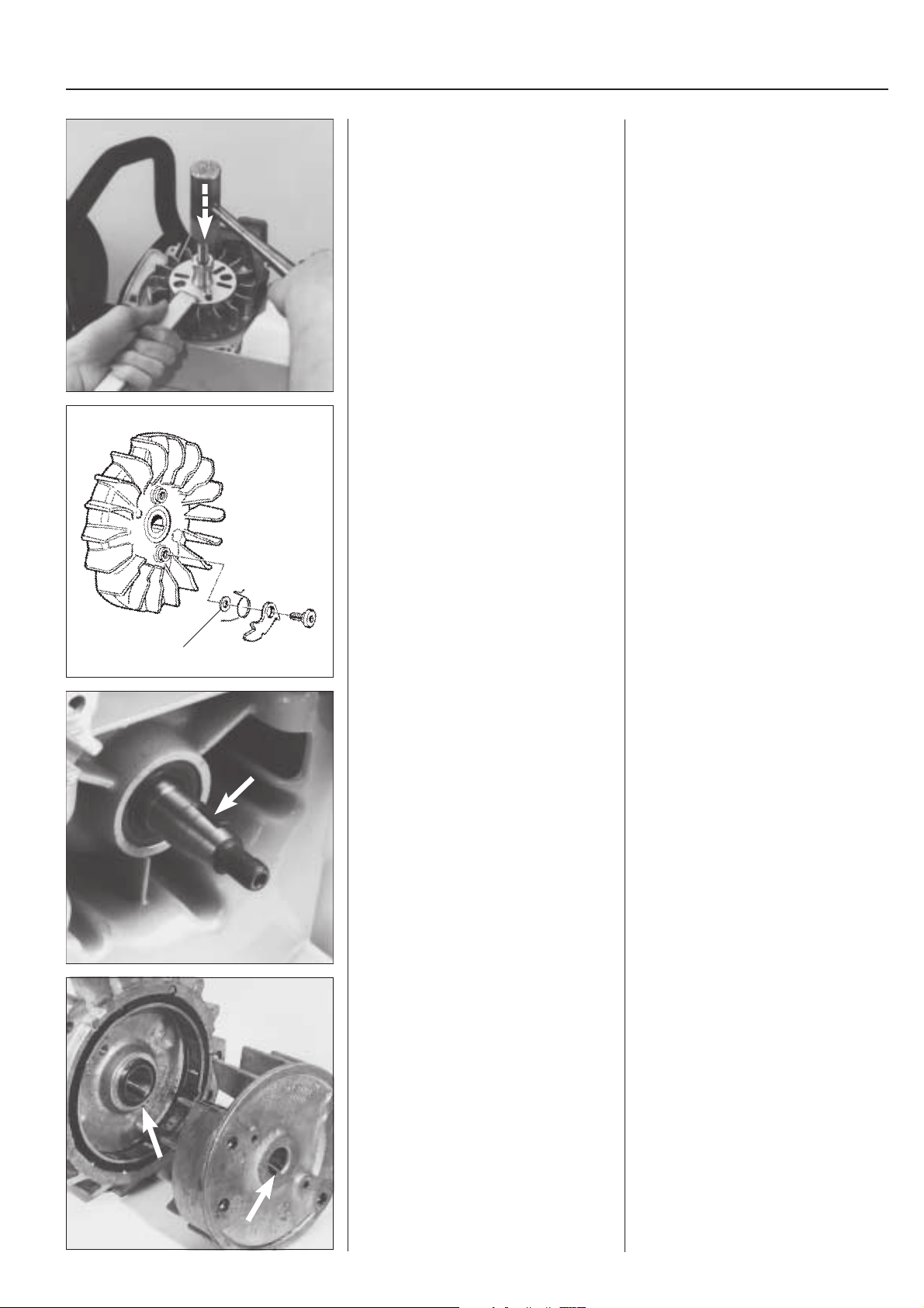
Tips!
Ta p t he flywheel puller screw sharply with
a hammer if the flywheel sits tight.
Starter pawls
Mod. 650, 700, 950, 1250
Check the starter pawls for wear and
damage.
Replace damaged parts.
The pawls are mounted on the flywheel
with a contact screw.
Pay attention to the spacer washer (A)
during dismantling and assembly.
Tips!
The flywheel may sit very tightly on the
shaft. To simplify dismantling - tap the
flywheel pullers screw sharply a few
times. Hold the engine in the air with the
handle on the flywheel puller.
Starter pawls
Mod.650, 700, 950, 1250
Check the starter pawls for wear and
damage.
Replace damaged parts.
The pawls are mounted on the flywheel
with contact screw and spacer washer
(A).
It is important not to forget the washer
during assembly.
Check that the pawls move freely.
A
Assembly
Check that the keyway and key in the
crankshaft are undamaged. (Mod. 650,
700, 1250)
Check that the keyway and the cast key
(mod. 950) in the flywheel are undamaged.
Fit the flywheel.
Assembly
Check that the keyway and key in the
crankshaft are undamaged. (Mod. 650,
700, 1250)
Fit where appropriate a new key and
make sure that it is positioned correctly in
the keyway.
Check that the keyway and the cast key
(mod. 950) in the flywheel are undamaged.
Fit the flywheel and check that the key
and keyway are correctly positioned
before the flywheel nut is tightened.
Tighten the nut with tightening torque 25–
35 Nm.
17
Page 19

2
Ignition system
0,3 – 0,5 mm
Fit the ignition module.
Adjust the air gap (0.3 –0.5 mm/0.012–
0.020").
Fit the other cables.
Fit the other parts in the reverse order to
dismantling.
502 51 34-06
Fit the ignition module.
Adjust the air gap to the correct size (0.3
–0.5 mm/0.012–0.020").
See also page 14–15.
Fit the other cables and make sure that
they are correctly positioned in the cable
grooves etc. so that they cannot be
damaged.
Fit the other parts in the reverse order to
dismantling.
18
Page 20
Fuel system
3.
Contents
Air filter ......................................................................... 20
Centrifugal cleaning (Active) ....................................... 21
Fuel filter ...................................................................... 22
Carburettor, dismantling/assembly .............................. 23
Carburettor design ....................................................... 25
Jets .............................................................................. 25
Speed limiter ................................................................ 26
Compensation device for blocked air filter .................. 26
Disassembly of the carburettor ................................... 27
Assembly of the carburettor ........................................ 30
Carburettor setting ....................................................... 32
Ta nk air v en t . .. . .. ... . .. .... . .. .... . .. .... . .. .... . .. .... . .. .... . .. .... . .. ... 34
Throttle control ............................................................. 35
Trouble shooting .......................................................... 40
19
Page 21
3
Fuel system
In addition to the fuel tank and carburettor, the fuel
system also includes the air filter, fuel filter and
tank vent.
All these components interact to ensure that the
engine will have the optimum mixture of fuel and
air to make it as efficient as possible. Very small
deviations in the carburettor setting, or fouling of
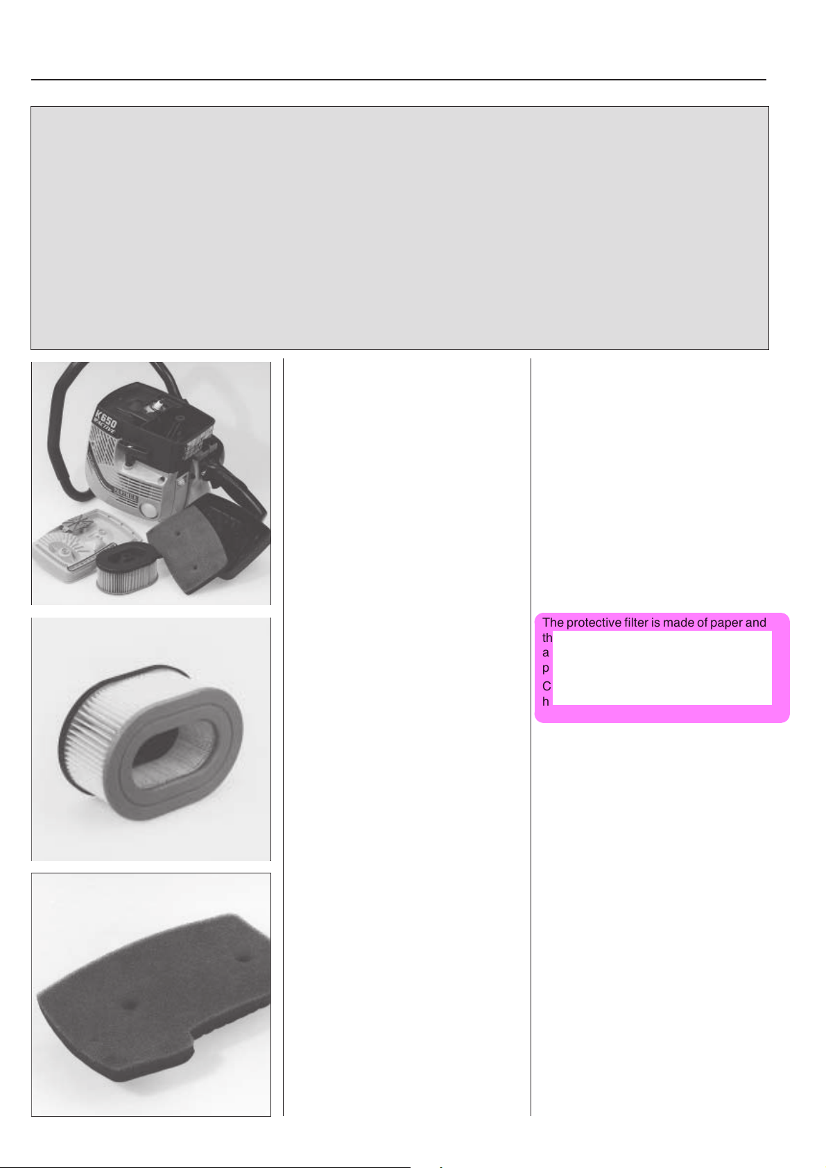
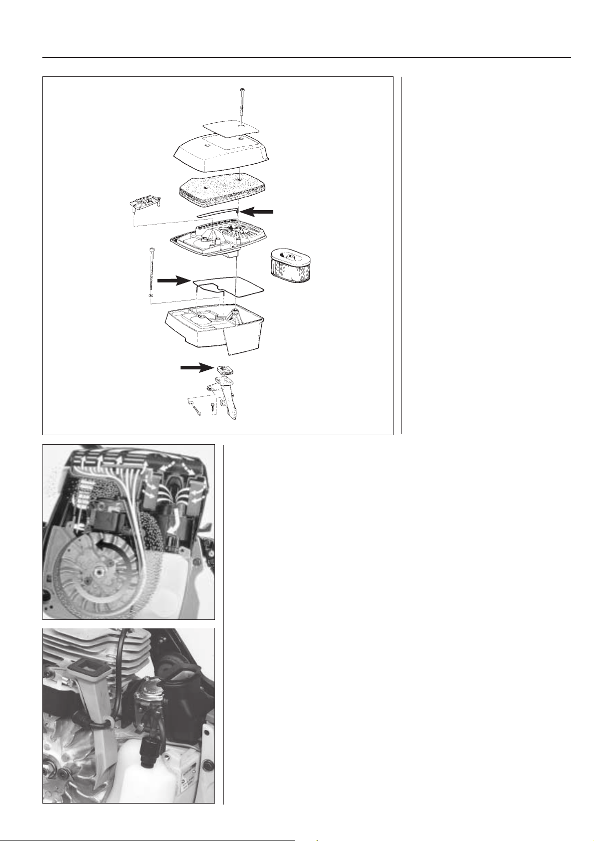
Air filter
Mod. 650, 700, 950, 1250
Release the screws and lift off the air filter
cover with the main filter, intermediate
wall and protective filter.
the air filter, have a great effect on the running and
efficiency of the engine.
There are different makes of carburettors on our
different models, but the function and repair
techniques are basically the same.
! WARNING!
Do not clean the air filter in petrol. Health
hazard!
Air filter
Mod. 650, 700, 950, 1250
Release the two screws which hold the
air filter cover (mod. 1250 three screws).
Lift off the cover with main filter, intermediate wall and protective filter.
Clean the protective filter by tapping it
against your hand.
Clean the main filter carefully in lukewarm
soapy water.
Soak it in air filter oil (Partner) and squeeze
out the excess before refitting.
The protective filter is made of paper and
therefore must not be cleaned in water or
any other liquid, and neither with compressed air.
Clean the filter by tapping it against your
hand.
Clean the main foam plastic filter in
lukewarm soapy water. Air dry the filter
and soak it in air filter oil and squeeze out
the excess before refitting.
If the filter is damaged it should be replaced
with a new one.
20
Page 22
Fuel system
K650/700
3
When the filter and covers are fitted it is
very important to make sure that all the
seals are undamaged and correctly
positioned.
Seals which do not seal properly result in
less efficient centrifugal cleaning and rapid blockage of the air filter.
Increased wear on the piston and cylinder barrel as a result of inferior air cleaning
shortens the engine’s service-life.
Centrifugal cleaning (Active)
Mod. 650, 700
Considerably longer cleaning intervals for the air filter are achieved by using the
centrifugal force during the filtering of the intake air to the carburettor.
By means of using the centrifugal force the heavier impurities are thrown out towards
the periphery of the air spiral and on past the cylinder.
The air to the carburettor is taken up by the centrifugal cleaning nozzle and the finer
impurities are effectively captured in air filter.
For centrifugal cleaning to be as efficient as possible it is important that:
1. The centrifugal cleaning nozzle is clean from deposits.
2. The connection of the nozzle to the carburettor chamber is tight.
3. The nozzle attachments are not broken.
4. The fan spiral and air conductor are clean.
The centrifugal cleaning nozzle is accessible for cleaning or replacement after
dismantling the starter unit and air conductor.
21
Page 23

3
Fuel system
Fuel filter
Mod. 650, 700
The fuel filter can be taken out through
the tank's filler hole.
502 50 83-01
Clean the filter externally if it is not too
severely fouled.
Replace the filter if necessary.
Fuel filter
Mod. 650, 700
On the fuel pipe in the tank there is a fuel
filter. This is accessible through the filler
hole. Pull out the filter with your fingers or
by means of tool 502 50 83-01.
Remove the tank cap completely.
If the filter is not too severly fouled it can
be cleaned externally by means of a brush.
Otherwise it must be replaced.
Check the fuel pipe for cracking and
leakage.
NOTE!
Make sure that the filter's connecting collar
is pressed as far as possible in the fuel
pipe.
A
Mod. 950, 1250
The easiest way to take the fuel filter out
through the fuel tank refill hole is with tool
502 50 83-01.
Mod. 950, 1250
The fuel filter is located on the hose in the
fuel tank. It is accessible through the refill
hole.
Remove the tank fuel cap completely.
Pull out the filter with tool 502 50 03-01.
Pull the metal ring (A) from the filter
connection and then pull the filter off the
hose to either clean it or replace it.
A
502 50 83-01
Fuel hose
All models
Remove the fuel filter and connect
pressure tester No. 501 56 27-01. Pump
up the pressure to about 100 kPa and
observe whether any bubbles are formed.
Fuel hose
All models
Remove the fuel filter and connect
pressure tester No. 501 56 27-01.
Pump up the pressure to about 100 kPa.
Leakage and cracks in the hose are easy
to detect if any bubbles are formed.
22
30
3
5
5
2
40
0
2
200
250
4
150
5
15
300
100
0
5
350
10
50
5
400
5
5
0
0
0
6
501 56 27-01
Page 24
Fuel system
3
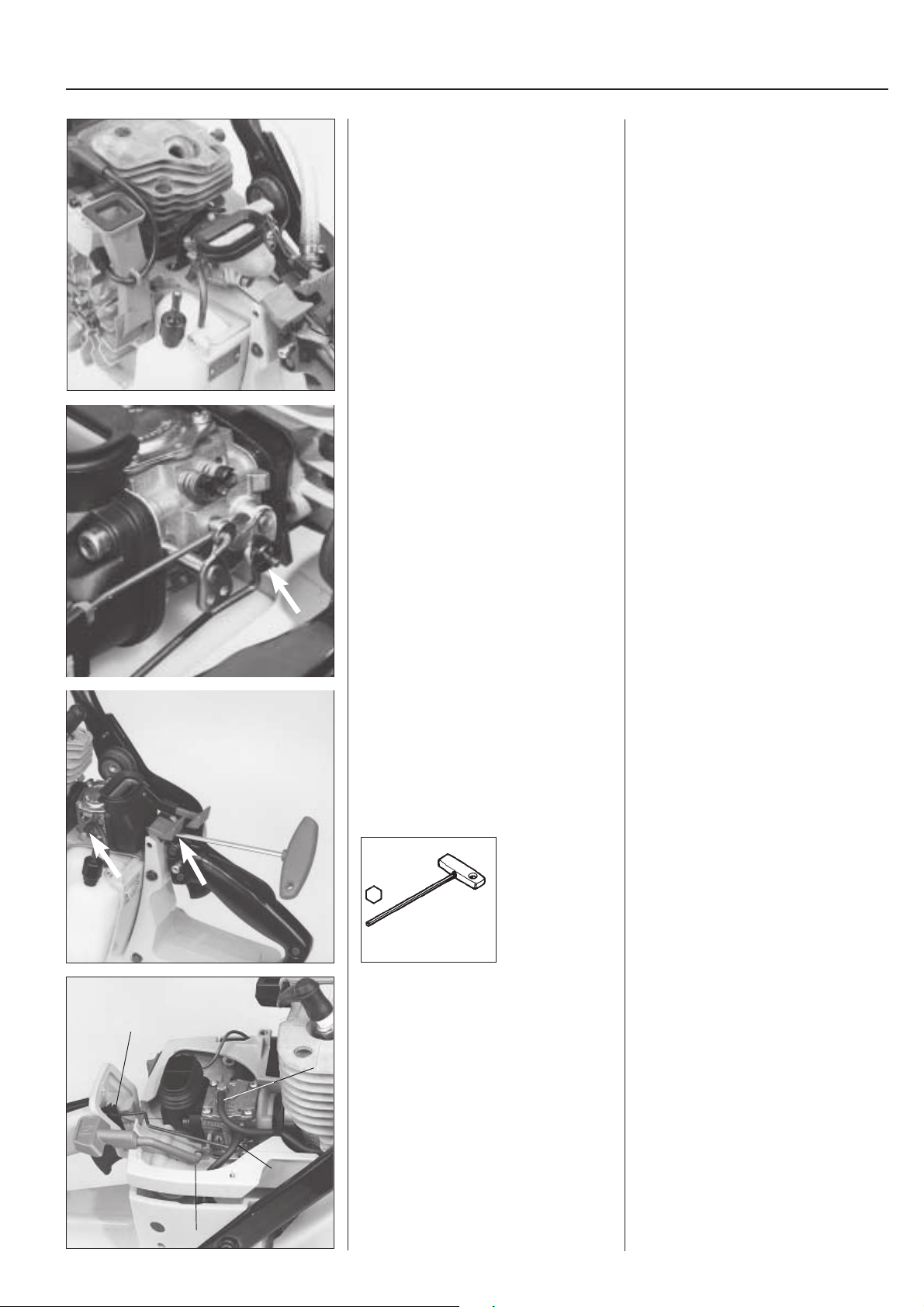
Carburettor
Dismantling, all models
Dismantle all covers and air filters so that
the carburettor becomes accessible.
Blow clean the carburettor chamber with
compressed air.
Mod. 650, 700
Remove the screw guide and lock washer which holds the throttle push rod at
the lever.
Carburettor
Dismantling, all models
Dismantle all covers and air filters so that
the carburettor becomes accessible.
Close the choke flap to prevent dirt penetrating into the engine.
Blow clean the carburettor chamber with
compressed air.
Mod. 650, 700
1. Remove the screw guide from the
carburettor’s adjusting screws.
2. Bend away the lock washer which
holds the throttle push rod at the lever
by means of a screwdriver.
NOTE!
EPA-models have fixed jets and consequently do not have screwdriver guides.
Remove the fuel hose.
Release the carburettor screws and lift
off the carburettor together with the choke
control, air filter connection, and middle
piece.
502 50 18-01
Carburettor
4
2
Mod. 950
Blow clean the carburettor area with
compressed air before the carburettor is
removed.
1
3. Remove the fuel hose from the carburettor.
4. Unscrew the carburettor screws. Insert
hex key 502 50 18-01 through the
hole in the stop control when the left
screw is to be unscrewed.
5. Lift off the carburettor together with
the choke control, air filter connection
and middle piece.
For service procedures see ”Disassembly
of carburettor”.
Carburettor
Mod. 950
Dismantle all covers and air filter. Blow
clean the carburettor area with
compressed air.
Dismantle the following:
1. Impulse hose
2. Fuel hose
3. Choke lever
4. Throttle lever (from throttle control)
3
23
Page 25
3
Fuel system
Dismantle the screw (A) and then the two
carburettor screws.
Lift off the carburettor.
A
502 50 18-01
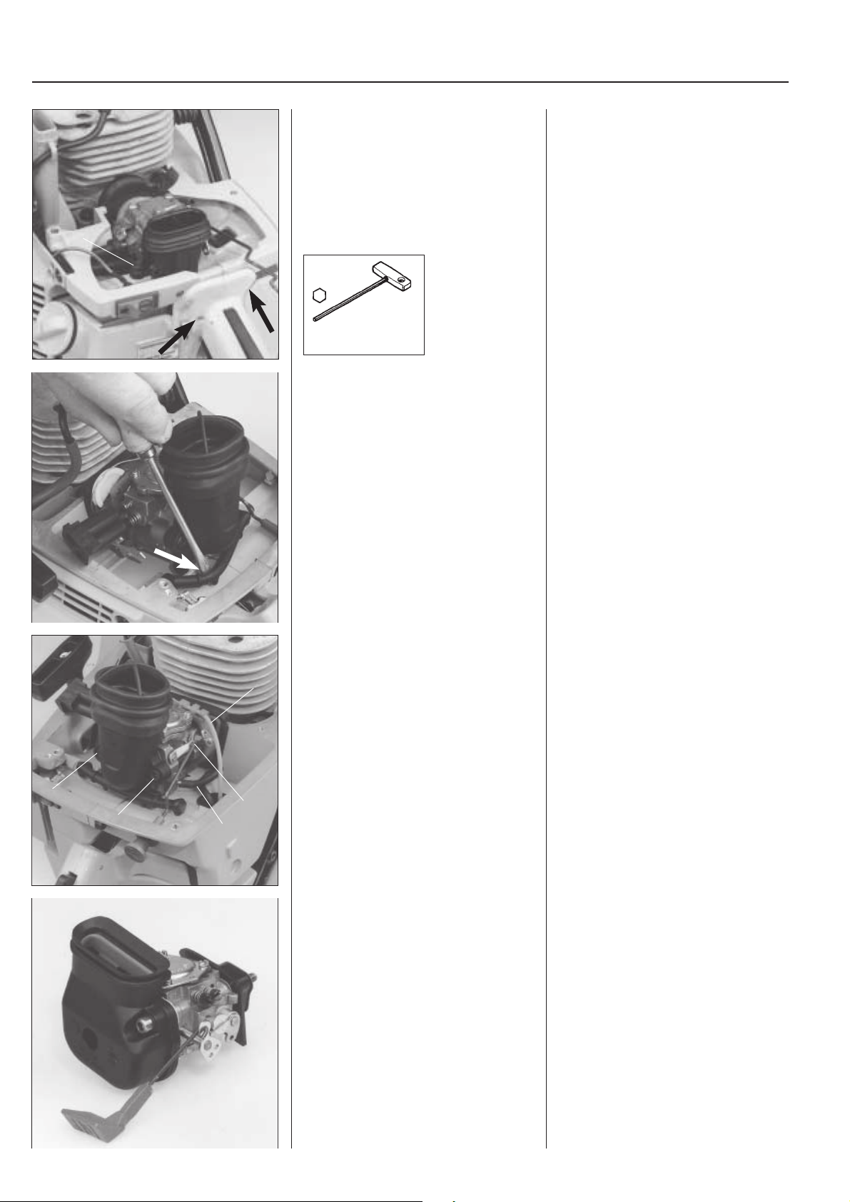
Mod. 1250
Press off the rubber support from the
carburettor intake.
Remove the screw (A) and then the two
carburettor screws.
Insert key 502 50 18-01 through the hole
in the crankcase and tank part.
Lift off the carburettor together with the air
filter connection and throttle lever.
Fit in the reverse order to dismantling.
Mod. 1250
Press off the rubber support from the
carburettor intake with a screwdriver.
NOTE!
Do not pull off the support from the
crankcase since it is difficult to refit without
separating the crankcase and tank part.
Dismantle the fuel hose.
Unscrew the carburettor screws, remove
4
2
3
2
1
the choke lever and hook off the throttle
wire.
Fit in reverse order to dismantling.
Assembly
Mod. 650, 700
Fit the carburettor in the reverse order to
dismantling.
1. Dismantle the fuel hose.
2. Unscrew the carburettor screws.
3. Remove the choke lever from the
lever on the carburettor.
4. Hook off the throttle wire
Lift off the carburettor together with the
intake neck.
Fit in the reverse order to dismantling.
Assembly
Mod. 650, 700
Fit the carburettor to the cylinder in the
reverse order to dismantling.
Use new seals.
Place the air filter connection (with
screws), choke control and middle piece
on the carburettor.
Hold the complete carburettor unit against
the cylinder. Press down the choke control
in its guide and tighten the screws. Check
that the seal closest to the cylinder is
correctly positioned! Connect the throttle
push rod and fit the screw guide over the
carburettor’s adjusting screws.
24
Page 26
Fuel system
3
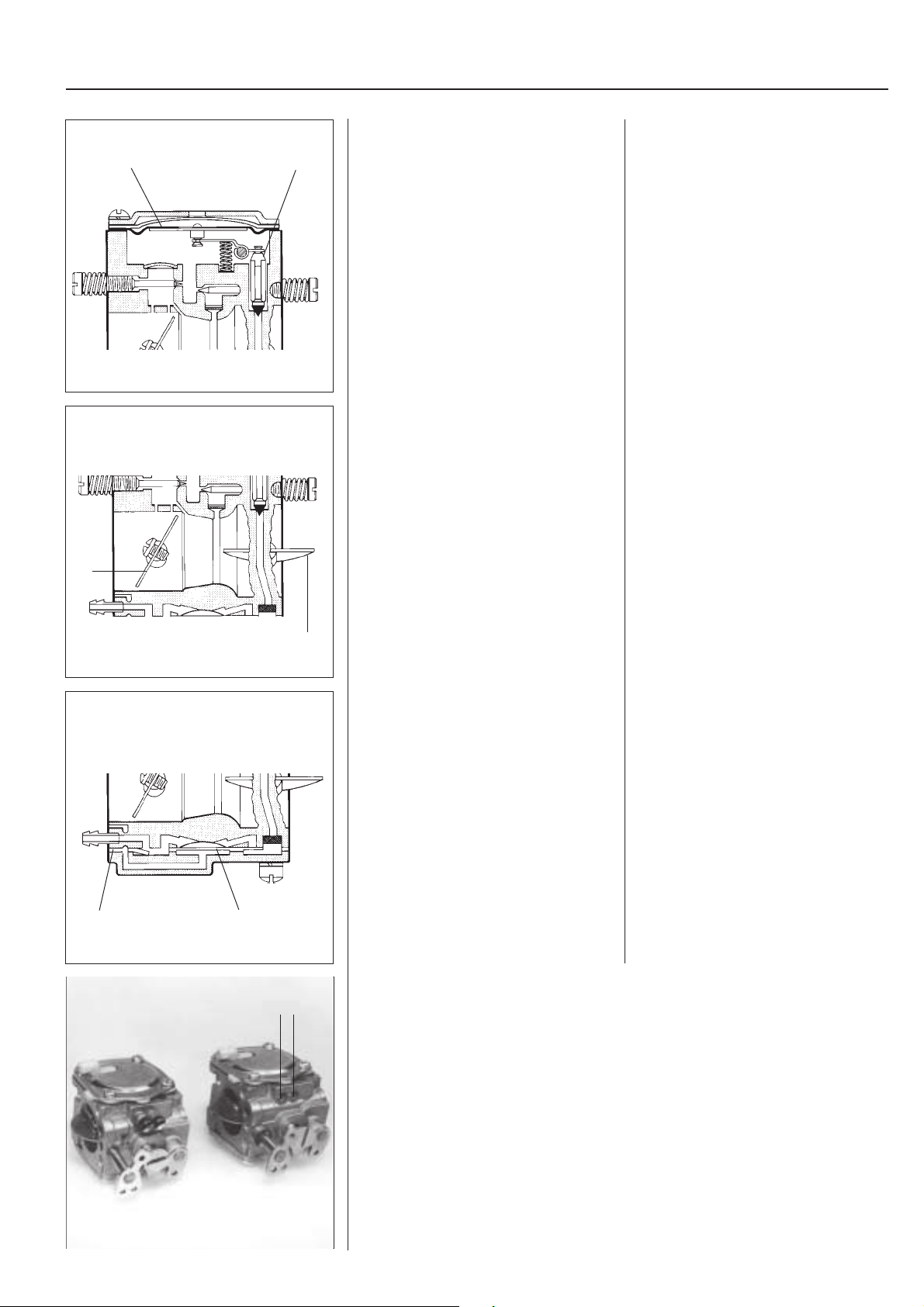
Carburettor design
D
F
C
The carburettor can be divided into three
different functional units: the metering
section, mixing section, and pumping
section.
Metering section
The nozzles and control function for the
fuel are placed here.
The mixing section
The fuel and air are mixed here.
Carburettor design
The carburettor can be divided into three
different functional units: the metering
section, mixing section, and pumping
section.
Metering section
The nozzles and control function for the
fuel are placed here.
The needle valve (C) and metering diaphragm (D) are vital parts for the functioning of the carburettor.
The mixing section
The fuel and air are mixed to the correct
proportions in this part of the carburettor.
The choke (E) and throttle valves (F) are
placed here.
The main jet nozzle is located in the
middle of the venturi (the narrowest point
on the inlet).
E
Pumping section
This pumps fuel from the tank to the
carburettor.
H
G
Pumping section
The pump diaphragm (G) which pumps
fuel from the tank to the carburettor’s
metering unit is located here.
The membrane is activated by pressure
variations in the engine crankcase via an
impulse channel (H).
If the channel is blocked, e.g. by grease
or an incorrectly turned gasket, the pump
will not function and the engine will not
start.
Jets
A A
EPA-models have fixed carburettor jets, which means that the fuel/air mixture can not
be adjusted manually.
The right-hand carburettor in the illustration has fixed jets (A).
The nozzles can be cleaned and possibly changed once the sealing plugs have been
removed.
25
Page 27
3
Fuel system
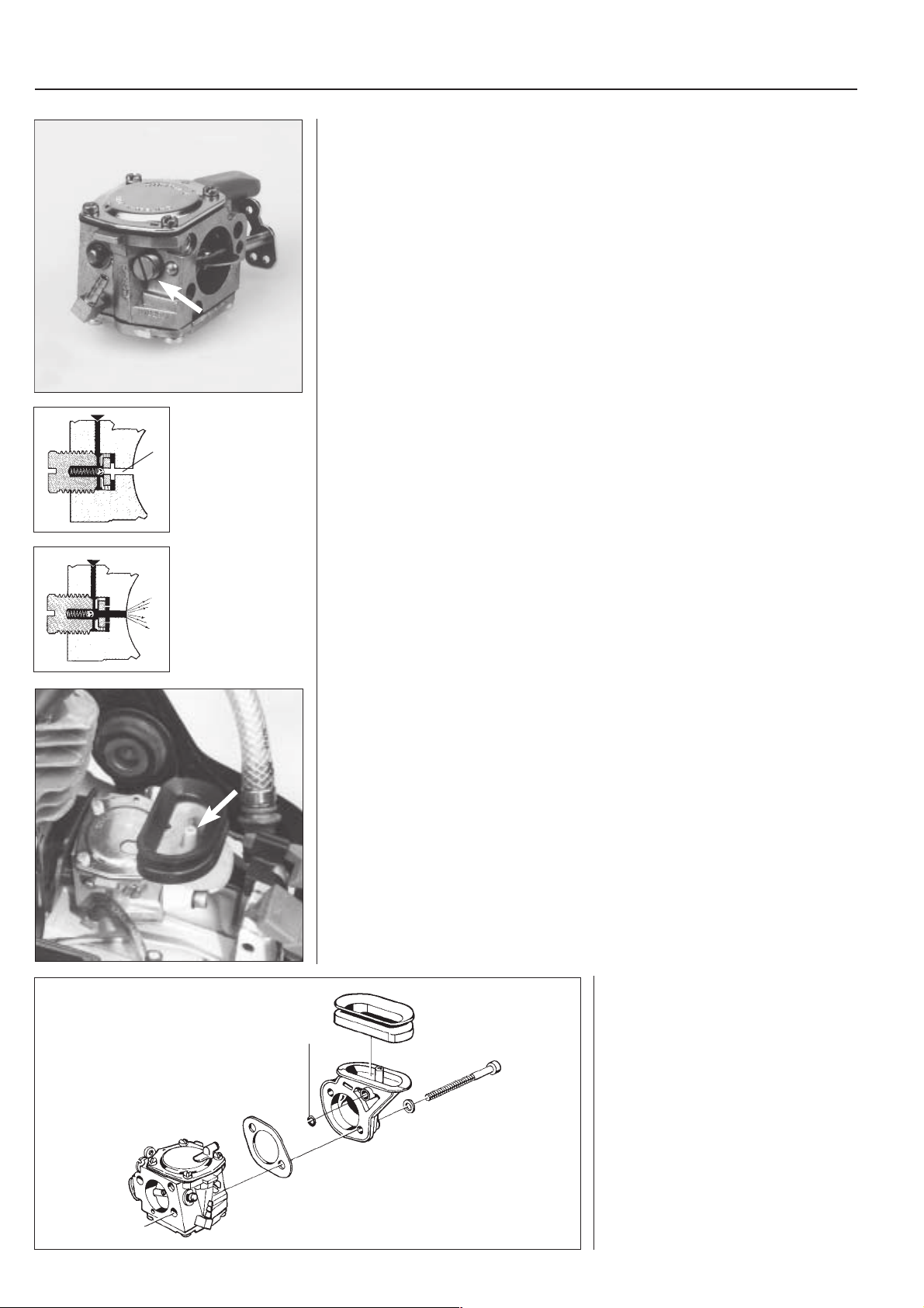
Speed limiter
Mod. 650, 700
A speed limiter is fitted on the side of the carburettor housing.
The speed limiter is fixed with Loctite and should not be released during servicing of
the carburettor.
When the engine speed is less than 9,200 rpm the ball seals the extra fuel channel (A).
The pressure of the spring presses the ball against the seat with a precise proven
A
pressure.
9600 r/min
When the engine speed exceeds the speed limit (9,600 ± 400 rpm) the spring-loaded
ball opens the extra fuel channel (A). The engine thereby receives extra fuel, begins to
putter and stops overspeeding.
Compensation insert for blocked air filter
The carburettor has been fitted with a compensation insert to prevent the engine
receiving an increasing amount of fuel as the air filter becomes blocked. This transfers
the underpressure in the carburettor’s inlet to the top of the metering diaphragm, as
opposed to the atmospheric pressure in a standard carburettor. The pressure difference
between the top and bottom of the diaphragm therefore remains constant and does not
increase as the air filter becomes blocked. The fuel supply to the carburettor’s main jet
nozzle is therefore always maintained at the correct level.
Check that the small O-ring (A) is in place
when the air filter union is installed.
A
It is important for correct function of the
compensation device that the O-ring is
neither damaged or missing.
26
Page 28
Fuel system
Combinations of carburettors, induction pipe, seals, screwdriver guides
K650 Active, K700 Active
Carburettor Induct. pipe Seal Insert, seal Screwdriver guide
HS175E 503 28 03-20 506 21 41-01 506 22 65-01 Black
Not compensated Black
K650 Active II, K700 Active II
Carburettor Induct. pipe Seal Insert, seal Screwdriver guide
HS175F 503 28 04-03 506 21 41-01 506 25 34-01 506 25 33-01 Blue
Compensated, blue insert Black Moulded Blue
HS175G 503 28 04-04 506 21 41-01 506 25 34-01 506 25 33-01 Blue
Compensated,blue insert Black Moulded Blue
Small needle valve
HS175G 503 28 04-08 506 26 72-01 506 26 85-01 –
Comp., green insert, EPA Blue Moulded
HS175L 503 28 04-15 506 31 16-01 506 26 85-01 –
Comp., yellow insert, EPA Yellow Moulded
To we r m odel
HS175L, 503 28 04-16 506 31 16-01 506 26 85-01 Grey
Comp., grey insert, EPA Grey Moulded
To we r m odel
Rubber foam, bonded to cyl. housing
3
There are different sizes and versions of carburettors on the different models, but in
terms of servicing they are all treated in the same way.
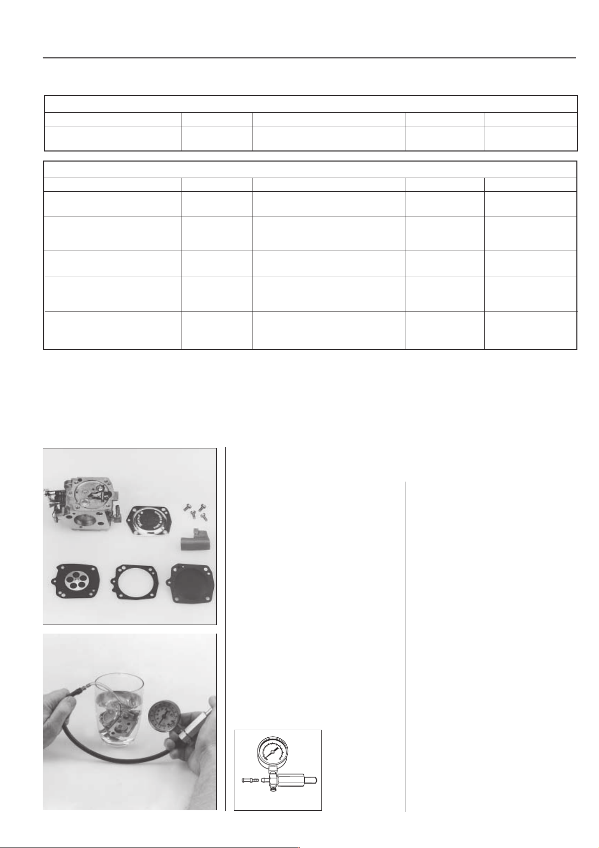
Dismantling of the
carburettor
Remove the screw driver guide and cover
for the metering diaphragm.
Check the diaphragm for damage.
Replace if necessary.
Dismantling of the
carburettor
Remove the screw driver guide over the
adjusting screws.
Remove the 4 screws for the metering
diaphragm cover.
Lift off the compensation insert and the
diaphragm.
Check the diaphragm for holes and wear.
Replace the diaphragm if necessary.
Pressure test the metering system.
Connect pressure tester 501 56 27-01 to
the fuel pipe nipple.
Submerge the carburettor in a basin with
petrol to simplify inspection for leaks.
Pressure test with 0.5 bar.
No leakage is permissible.
30
3
5
5
2
4
0
0
2
200
250
4
150
5
15
300
100
0
5
350
10
50
5
400
5
5
0
0
0
6
501 56 27-01
27
Page 29
3
Fuel system
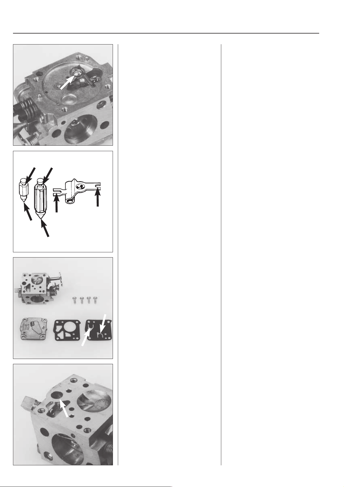
In the event of leakage - dismantle the
needle valve.
Check the needle valve and lever for
wear.
Replace damaged parts with new ones.
In the event of leakage dismantle the
needle valve.
Release the screw and lift off the lever,
shaft, needle valve and spring.
Check the needle valve for damage at the
point and the groove for the lever.
Check the lever for wear in the grooves
for the needle valve and the diaphragm.
Replace damaged parts with new ones.
If the new needle valve also leaks the
fault may be that the seat for the valve is
damaged.
Remove the pump diaphragm.
Check the diaphragm for damage.
Remove the fuel strainer.
Remove the screws which hold the cover
over the pump diaphragm.
Lift off the cover, gasket and diaphragm.
Check the diaphragm for damage on the
valve tongues. Hold it up to a lamp to
inspect for holes in the material.
Carefully remove the fuel strainer, e.g. by
using a needle.
28
Page 30

Fuel system
3
Unscrew the nozzle needles.
L
H
On EPA models which have fixed nozzles, the nozzles can be cleaned or changed once
the seal plugs have been removed.
Carefully drill a small hole (Ø 2 mm) in the plug and prise it away with a pointed tool.
NOTE!
Use a suitable-sized drift when the plug is installed, to give correct sealing.
Unscrew the nozzle needles.
NOTE!
Notice the two types of needles and how
they are positioned (e.g. the H-needle is
slightly shorter than the L-needle).
Dismantle the welch plug (1) and main jet
nozzle (2).
1
2
Check the valves and valve shafts for
wear.
Replace if necessary.
Drill a small hole in the welch plug (1) and
carefully remove it with a pointed tool.
Press out the main jet nozzle (2) with a
suitable mandrel.
Dismantle valves and valve shafts. If these
parts are worn the engine will pink.
Always replace the valve and valve shafts
at the same time.
29
Page 31

3
Fuel system
650/700
Assembly of the
carburettor
Blow clean the carburettor housing.
Fit a new welch plug.
Fit a new main jet nozzle.
Fit the valves and valve shafts.
NOTE!
Use Loctite on the valve screws.
Fit the pump unit parts in the reverse
order to dismantling.
Assembly of the
carburettor
Blow clean the carburettor housing.
Fit a new welch plug.
Use a suitable mandrel to achieve complete tightness.
Press in a new main jet nozzle. It should
lie flush with the carburettor housing.
Fit the valves and valve shafts.
NOTE!
Check that the valves are correctly turned and that they seal completely in
closed position.
Use Loctite on the valve screws.
Tips!
Number designations on the valves
should be able to be read from outside.
Fit the different parts in the metering unit
in the reverse order to dismantling.
Replace the fuel strainer if it is damaged
or cannot be cleaned.
Fit the pump unit parts in the reverse
order to dismantling.
Place the pump diaphragm closest to the
carburettor housing, followed by the
gasket and cover.
Fit the different parts in the metering unit
in the reverse order to dismantling.
NOTE!
The H-needle is slightly shorter than the
L-needle.
30
Check that the lever is level with the
carburettor housing.
High setting = too much fuel.
Low setting = too little fuel
Page 32

Fuel system
3
Check that the carburettor is tight.
No leakage is permissible at 50 kPa
pressure.
30
3
5
5
2
4
0
0
2
200
250
4
150
5
15
300
100
0
5
350
10
50
5
400
5
5
0
0
0
6
501 56 27-01
Fit the metering diaphragm and compensation insert for air filter blocking.
Connect pressure tester
No. 501 56 27-01 to the fuel inlet in the
carburettor.
Pump up to 50 kPa pressure.
Submerge the carburettor in a jar with
petrol to simplify inspection for leakage.
No leakage is permissible.
Place the gasket on the carburettor
housing and then the metering diaphragm.
NOTE!
Make sure that the pin on the diaphragm
goes into the groove on the lever.
Fit the blue compensation insert and then
the cover.
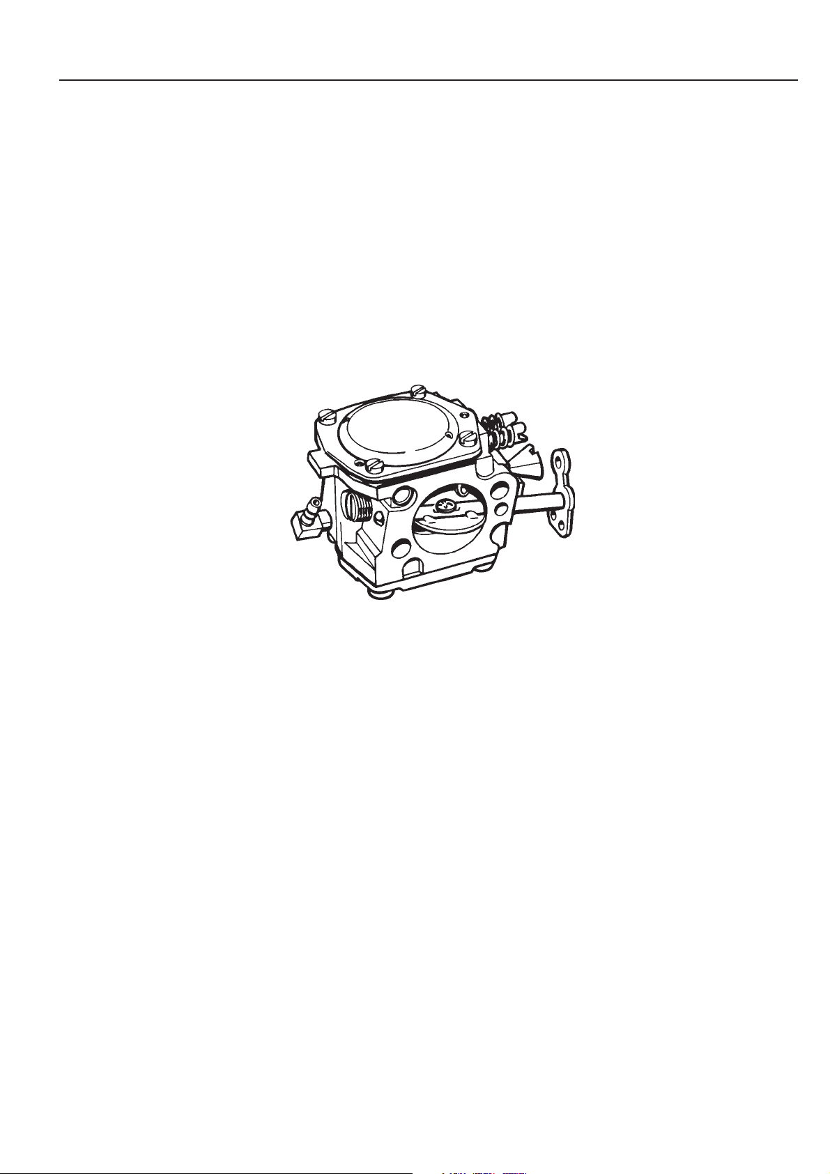
Tillotson HS
Mod. 950
The carburettor is of Tillotson (HS 282A)
manufacture, and has in principle the
same design as the carburettor for mod.
650, 700.
The speed limiter, however, has been
replaced by an electronic limit via the
ignition system.
The adjustable jets have been re-placed
by fixed jets.
A = Main jet (high speed)
D
A
C
B
B = Low speed jet (behind washer
plug)
C = Idle screw
D = Main nozzle
E
E = Part throttle jet
F = Fuel screen
The service method for this carburettor is
F
the same as for mod. 650, 700.
The main jet (A) can be dismantled for
cleaning or replacement.
To g ai n ac cess to th e l ow s pe ed jet (B ) t he
welch plug must be removed.
31
Page 33

3
Walbro WG 9
Fuel system
A
C
B
E
D
Mod. 1250
The carburettor on this model is of Walbro
manufacture.
The service method is the same as for the
Tillotson carburettor. Note the small Oring (A) placed on the compensation
device.
This carburettor does not have a speed
limiter either.
A = O-ring
B = Main nozzle
C = Main jet (high speed)
D = Low speed needle
E = Adjuster screw for idle speed
F = Fuel screen
The main jet (C) can be dismantled for
cleaning or replacement.
F
Fit the carburettor on the engine in the reverse order to dismantling. Use new gaskets
Check that the gaskets are turned the right way round so that the impulse channel is
not blocked.
H
T
L
Carburettor setting (not EPA models)
WARNING!
!
When test running the engine in connection with the adjustment of the
carburettor the clutch, cutting arm and cutting disc must always be fitted.
Otherwise there is a risk that the clutch may release and cause serious
personal injury.
Function
The purpose of the carburettor is to supply a combustible mixture of air and fuel to the
cylinder.
The volume of this mixture is regulated with the throttle control.
The composition of the mixture of air and fuel is regulated with the adjustable nozzles
”H” and ”L”.
32
The carburettor should be adjusted if:
● The cutting disc rotates when the engine is idling.
● The engine speed does not go down to idle from full throttle within 3-5 seconds.
● The engine does not run on idle.
● The engine does not respond quickly to the throttle.
● The engine seems to lack power.
NOTE!
EPA models have carburettors with fixed jets "H" and "L". This means that they can not
be adjusted
Page 34

7/8
Fuel system
The adjustment of the carburettor may vary somewhat depending on the humidity,
H
L
T
1 1/4
temperature and air pressure.
L= Low speed nozzle
H= High speed nozzle
T= Adjuster screw for idling
● With the L and H nozzles the fuel volume is adjusted to the air flow which the
opening of the throttle control permits. If they are screwed clockwise the air/fuel
mixture becomes lean (less fuel) and if they are screwed anti-clockwise the air/
fuel mixture will become rich (more fuel).
A lean mixture gives higher revs and a rich mixture gives lower revs.
● The T-screw regulates the position of the throttle control during idling. If the Tscrew is screwed clockwise a higher idling speed will be obtained, and if it is
screwed anti-clockwise a lower idling speed will be obtained.
Basic setting (not EPA models)
The carburettor is given a basic setting when tested at the factory. This basic setting is
slightly ”richer” than the optimum setting and should be maintained during the first few
hours the engine is used, after which it should be fine adjusted. The basic setting can
vary between:
H= 7/8 to 1 turn
L= 1 to 1 1/4 turn
The basic setting should be made when the engine is switched off.
Check that the air filters are clean.
Screw the nozzle needles (H) and (L) carefully to the bottom (clockwise).
Then unscrew them to the recommended basic setting.
Start the engine and run until warm, for about 5 minutes.
If the engine’s idling speed is too high or too low adjust it with the idling adjuster screw
(T) until the cutting disc just stops/begins to rotate (approx. 2,500 rpm).
Check with tachometer 502 71 14-01.
3
501 60 02-02
502 71 14-01
Low speed nozzle (L) (not EPA models)
Run at full throttle a few times and check that the engine accelerates without delay. If
an adjustment is necessary try to achieve maximum idling speed by slowly turning the
low speed nozzle (L) clockwise until the engine hesitates from lack of fuel, and then
open the nozzle (anti-clockwise) 1/8 of a turn.
Check the acceleration of the engine.
NOTE!
If the low speed nozzle is set too lean (L-needle screwed in too far) this will result in
difficulty starting the engine. After a correct adjustment of the low speed nozzle (L) the
high speed nozzle (H) can be adjusted.
High speed nozzle (H) (not EPA models)
The engine has a carburettor with built-in speed limiter.
At maximum revs the engine receives an extra volume of fuel which prevents the engine
overspeeding. The speed limiter has a fixed setting and cannot be adjusted.
Screw in the H-needle to the limiting position where the engine begins to falter during
acceleration. Use short, rapid bursts from idling speed.
From this position the H-needle is then opened less than 1/8 of a turn (45°), which gives
the carburettor setting for maximum engine power.
Check with a tachometer that the engine does not overspeed the permissible maximum
speed (9,600 ± 400 rpm).
!
WARNING!
If the high speed nozzle is set too lean (screwed in too far clockwise) this will
reduce the power of the engine and can result in overheating and subsequent
damage to the engine.
The high speed nozzle (H) should be adjusted for maximum power and not
maximum speed.
33
Page 35

3
Mod. 650/700
L = 1 1/4
H = 7/8
Fuel system
Fine adjustment of the idling screw (T)
Adjust the idling speed with the adjuster screw (T).
The idling speed should be adjusted after the high and low speed nozzles have been
adjusted.
If it is necessary to adjust the idling screw turn the screw (T) first clockwise until the
cutting disc begins to rotate, and then anti-clockwise until the cutting disc stops rotating.
The idling speed is correctly adjusted when the engine speed (approx. 2,500 rpm) is
stable in all working positions.
There should be a good margin between the idling speed and the speed at which the
cutting disc begins to rotate.
WARNING!
!
Do not use the machine if the idling speed cannot be adjusted so that the
cutting disc stops rotating.
Mod. 950
L = fast / fixed / Fest / fixé
H = fast / fixed / Fest / fixé
Mod. 1250
L = 1 1/4
H = fast / fixed / Fest / fixé
B
A
Correctly adjusted carburettor
A correctly adjusted carburettor implies that the engine accelerates without hesitation
and does not putter at full throttle.
● If the L-nozzle is set too lean it can be difficult to start the engine and will result in
poor acceleration.
● If the H-nozzle is set too lean this will result in reduced power, poor acceleration and/
or engine damage.
● If the L- and H-nozzles are set too rich this will result in acceleration problems or low
working speed.
Tank air vent
All models
The tank air vent has a great influence on the function of the carburettor. If it is not
working properly then either overpressure or underpressure will develop in the fuel
tank.
Overpressure results in flooding the carburettor.
Underpressure implies a reduction of the fuel flow to the carburettor, or no fuel flow at
all.
The purpose of the tank air vent is to ensure that there is atmospheric pressure in the
fuel tank during all operating conditions.
Mod. 650, 700
The tank air vent consists of a nonreturn valve (A) which opens at a certain pressure
in both directions.
In one end of the valve (the smooth connection) a sintered metal filter (B) is connected
to prevent dirt from penetrating into the fuel tank.
34
Mod. 950
The tank vent valve (B) is accessible
when the tank part and crankcase have
B
A
been separated. It cannot be repaired
and must be replaced if it is defective.
Remember to clean the small metal filter
(A) in the end of the hose.
Mod. 950
The fuel tank venting is conducted via a
non return valve of the same design as on
the other machine models.
It is accessible when the tank unit and
crankcase are separated.
Remember when servicing to clean the
small metal filter (A) placed in the end of
the hose.
The non return valve (B) cannot be repaired and must be replaced if it is defective.
Page 36

Fuel system
3
Mod. 1250
Separate the tank unit and crankcase.
Prise away the non-return valve with a
screwdriver.
Install new components in reverse order.
Do not forget to clean the metal filter (A).
Mod. 1250
Separate the tank unit and crankcase just
enough to gain access to the tank vent.
Put a screwdriver between the fueltank
and the non-return valve.
Press the valve straight out from the
fueltank.
Install new components in reverse order
from removal.
The non-return valve can not be cleaned,
it must be replaced by a new one during
service.
Do not forget to clean the small metal
filter (A).
A
Function check
Empty the fuel tank and screw on the tank cap.
Connect a pressure gauge to the fuel hose.
Overpressure
2
Pump up a pressure of 50 kPa (0.5 kp/cm
The pressure should fall to 20 kPa (0.2 kp/cm2) within 60 seconds.
Underpressure
Reduce the pressure to –50 kPa (0.5 kp/cm
The pressure should increase to 20 kPa (0.2 kp/cm2) within 30 seconds.
If the tank air vent is not working it must be replaced with a new one. It cannot be cleaned
or repaired.
Throttle control
Dismantling, assembly
Mod. 650, 700
Remove the four screws which hold the
left-hand half of the grip.
).
2
).
Throttle control
Dismantling, assembly
Mod. 650, 700
Remove the four screws which hold the
left-hand half of the rear grip. Note that
they have different lengths.
505 38 13-08
35
Page 37

3
Fuel system
Lift off the half of the grip and the throttle
control.
Note the washer under the throttle control
and the sleeve inside the control.
Lift off the half of the grip.
NOTE!
One end of the return spring for the throttle
control catch goes in the hole on the
throttle control.
Lift off the throttle control. Note the washer under the throttle control and the
sleeve inside the control so that they are
not lost during cleaning.
Fit in the reverse order to dismantling.
Replace damaged or worn parts.
Fit all parts in the left-hand half of the grip.
1. Place the spring for the throttle control
catch in position round the pin with the
hole in it.
2. Place the throttle control catch in position.
36
Hook in the spring in the hole in the
throttle control and move it to the correct
position opposite the screw hole.
Lock the throttle control with the catch
and insert the screw in the throttle control’s
supporting sleeve.
3. Push the sleeve in the throttle control
from underneath.
4. Hold the sleeve in position with your
forefinger and hook the spring in the
hole in the throttle control.
5. Move the throttle control to the correct
position opposite the screw hole.
6. Press in the start throttle catch and
lock the throttle control in start position.
7. Insert the screw in the throttle control’s
supporting sleeve.
Page 38

Fuel system
3
Fix the spacer washer with a little grease
on the right-hand grip half.
Hook the throttle lever in the throttle control
and place the grip half in position.
Screw tight the screws and check the
function of the throttle control.
1
2
3
Mod. 950
Separate the tank unit and crankcase.
Press out the bearing pins (1) and (3) and
dismantle the safety catch and throttle
control.
8. Place the spacer washer in position
on the right-hand grip. Fix it with a
little grease.
9. Hook the throttle lever in the throttle
control and place the grip half in position.
NOTE!
Check that the spacer washer has not
moved.
10. Screw tight the screws and check the
function of the throttle control.
Mod. 950
Separate the tank unit and crankcase.
(Where appropriate see chapter on vibration damper.)
1. Press out the bearing pin (1) with an
appropriate punch (Ø 2.5 mm) far
enough so that the safety catch (2)
can be removed.
2. Press out the bearing pin (3) far
enough so that the throttle control can
be removed, where appropriate by
bending it with a screwdriver.
Fit the throttle control in the reverse order
to dismantling.
Fit the safety catch.
The spring should be to the right of the
catch (seen from behind).
Press in the bearing pin and check the
function of the catch.
Fit the throttle control in the reverse order
to dismantling.
1. Place the spring on the throttle control
and push in into the rear grip.
2. Press in the bearing pin and check
that the throttle control moves easily.
Fit the safety catch
3. Make sure that the throttle control
spring is on the right-hand side of the
catch (seen from behind) and that it
goes into the recess.
4. Press down the catch throttle lock in
the grip and press in the pin.
Check that the throttle lcok functions
properly.
37
Page 39

3 Fuel system
Mod. 1250
Separate the tank unit and crankcase,
and press off the three bearing pins.
Press the safety catches forwards/
downwards and lift them up at the back
edge.
Mod. 1250
Separate the tank unit and crankcase.
(Where appropriate see chapter on vibration damper.)
Press off the three bearing pins with a
suitable punch (Ø 2.5 mm).
Press down the safety catch, and press it
forwards (where appropriate with a small
screwdriver) so that it can be lifted up at
the back edge.
Pull the throttle control forwards and out
of the rear grip.
Inspect the different parts and replace
those which are damaged or worn.
Pull the throttle control forwards, out from
the rear grip. To simplify dismantling,
press with a small screwdriver on the
lever which the throttle wire is attached
to.
Inspect the different parts and replace
damaged or worn parts with new ones.
TIP!
Bend the end of the spring to a closed
loop. This simplifies fitting and prevents
the spring from being pressed out from
the recess at the hole where the spring
should slide freely.
38
Page 40

Fuel system
3
Fit the throttle control and safety catch in
the reverse order to dismantling.
Check that the spring on the catch goes
into the hole in the throttle control.
1. Push the throttle control with attached
throttle wire into the rear grip.
2. Enter the back edge of the safety
catch into the grip.
3. Check that the spring goes into the
hole in the throttle control.
4. Press down the safety catch until it
clicks into the throttle control.
5. Press in the three bearing pins and
check that the throttle control and
safety catch function as intended.
39
Page 41

3
Trouble-shooting chart
Fuel system
●●●●●●●
●●●
●● ●●●●●●●
●● ● ●●
●● ●●
●● ●● ● ● ● ● ●● ●●●●
●● ● ● ●
●●●● ●●
●
Metering system
26. Worn lever
27. Set too high
28. Set too low
29. Not free
30. Distorted
31. Improperly installed
Air system
12. Plugged air filter
13. Defective manifold gasket
14. Loose carburettor mounting screws
15. Worn throttle assembly
16. Incorrect throttle assembly
17. Loose throttle valve screw
32. Leaking (air/fuel)
33. Worn button
34. Improper assembly
35. Defective gasket
36. Loose diaphragm rivet
37. Hole in diaphragm
38. Loose cover screws
18. Throttle shaft too tight
19. Bent throttle linkage
20. Defective throttle spring
21. Bent throttle stop lever
22. Choke not functioning properly
23. Worn choke shaft
24. Worn choke valve
39. Foreign matter
40. Binding
25. Worn throttle valve
41. Worn needle body or tip
40
12345678910111213141516171819202122232425262728293031323334353637383940
Start
Start
A. Hard starting
●●● ● ●●●
A
B
C
carburettor
B. Fuel dripping from
C. Floods when
●●●●●● ●● ●●●●
Idle
D
engine is not
running
Idle (Low speed)
●
E
D. Will not idle
F
E. Rich idle
G
F. I dl e s with L-n ee dle
H
J
closed
G. Irregular idle
●●●●●●●●●●●● ●● ●● ●●●
●●●●●●● ●●●●●● ● ● ●
●● ● ● ●
●● ●●
Acceleration, deceleration
K
L
M
High speed
N
frequent adjustment
H. "L"-needle needs
idling
J. Loads up while
Acceleration and
deceleration
closing throttle
K. Will not accelerate
L. Engine stops when
●●●●●●●●● ●● ● ● ●●●●●
●●● ●●●●●
O
P
tion
M. Over-rich accelera-
Fuel system
3. Plugged tank vent
4. Plugged tank filter
5.Restricted fuel line
6. Dirt in fuel passage
throttle
High speed
N. Will not run at full
O. Low power
P. W il l n o t 4 c y cl e
7. Loose, damaged fuel line
8. Leak in pulse system
9. Restricted pulse channel
10. Loose pump cover screws
11. Def ect ive pu mp di aph rag m
Adjustments
1. Low speed needle (L)
2. High speed needle (H)
Page 42

Centrifugal clutch
4.
Contents
Dismantling, all models .............................................. 42
Dismantling, mod. 650, 700 ........................................ 42
Dismantling, mod. 950, 1250 ...................................... 44
Assembly, mod. 650, 700 ........................................... 45
Assembly, mod 950, 1250 .......................................... 46
41
Page 43

4
Centrifugal clutch
The centrifugal clutch has the purpose of
transferring the power between the engine and
the cutting equipment. As the name implies it
works according to the centrifugal principle.
This principle implies that the clutch's friction
shoes are slung outwards towards the clutch
drum at a specific engine speed. When the friction
against the drum becomes suf ficient it is driven
round at the same speed as the engine.
There is a certain degree of slip between the
clutch and the clutch drum during acceleration,
Dismantling
All models
Dismantle the complete cutting equipment
and unscrew the plug.
but also in the reverse case if the cutting equipment
should stick. This avoids irregular load alternations
on the crankshaft.
The engagement speed is carefully tested to that the
engine can run at idling speed without the cutting
equipment rotating.
!
WARNING!
Never start or test run the engine if the clutch
cover is removed. The clutch can come loose
and cause personal injury.
Dismantling
All models
Dismantle the front and rear belt cover,
cutting arm with cutting disc, and drive
belt.
Remove the air filter cover and air filter,
and unscrew the plug.
Mod. 650, 700
Fit piston stop No. 502 54 15-01 in the
spark plug hole.
Dismantle the clutch clockwise by means
of a suitable box spanner.
502 54 15-01
Ta ke th e clutch a pa rt.
Use pliers No. 502 50 49-01 and press
out the one clutch shoe.
Mod. 650, 700
Fit piston stop No. 502 54 15-01 in the
sparking plug hole.
Dismantle the clutch clockwise by means
of a suitable box spanner.
NOTE!
Do not drop the washer which lies behind
the clutch drum.
Press out the one clutch shoe with pliers
No. 502 50 49-01 as shown in the illustration.
42
502 50 49-01
Page 44

Centrifugal clutch
4
Place an object which is approx. 5.5 mm
(0.22") thick between the clutch shoe and
the spoke.
Bend away the clutch spring.
Clean and inspect the clutch parts for
damage and wear.
Min. 1 mm
Place an object (e.g. a nut) which is
approx. 5.5 mm (0.22") thick between the
clutch shoe and the spoke on the clutch
hub on the back of the clutch.
Bend away the clutch spring with a
screwdriver.
Clean and inspect the clutch hub’s spokes
and the clutch shoes for wear.
There must be material thickness of at
least 1 mm (0.04") left at the most worn
point on the clutch shoes.
All the shoes must be replaced at the
same time.
Inspect the wear on the clutch drum, the
pulley and the inner diameter.
It must not exceed 75.5 mm (2.97").
Replace the needle bearing if the clutch
drum is loose on the shaft.
Check the wear on clutch drum’s inner
diameter. It must not exceed 75.5 mm
(2.97"). If so, replace the clutch drum.
Check also the wear on the pulley. If the
side surfaces are heavily worn and/or
damaged the clutch drum must be
replaced.
If the needle bearing in the clutch drum is
worn (the drum is loose on the shaft) it
should be replaced with a new one.
Press out the bearing with a vice and a
suitable sleeve (Ø 17.5 mm, 0.69").
43
Page 45

4
Centrifugal clutch
Mod. 950, 1250
Dismantle all the cutting equipment and
unscrew the plug.
Fit piston stop No. 502 54 15-01 and
dismantle the clutch clockwise.
502 54 15-01
Remove the clutch springs with a small
screwdriver.
Mod. 950, 1250
Dismantle the front and rear belt covers,
cutter arm with cutter disc and drive belt.
Remove the air filter covers and air filter,
and remove the plug.
Fit the piston stop No. 502 54 15-01 in the
plug hole and dismantle the clutch
clockwise.
Remove the clutch springs with a small
screwdriver.
Min. 1 mm
Clean and inspect the clutch parts for
damage and wear.
Inspect the clutch drum for wear on the
mating surfaces for the centrifugal clutch
and drive belt.
Clean and inspect the clutch hub spokes
and the clutch shoes for wear.
There must be at least 1 mm of material
left at the most worn part of the clutch
shoes.
All the shoes must be replaced at the
same time.
Inspect the clutch drum for wear on the
mating surfaces for the centrifugal clutch
and drive belt.
The inner diameter of the clutch drum
must not exceed 79.8 mm.
Replace worn parts.
44
Page 46

Centrifugal clutch
4
Assembly
Mod. 650, 700
Press in the new needle bearing until it is
flush with the
drum’s hub.
Fit together the centrifugal clutch.
Place two clutch shoes and the spring on
the clutch hub.
outer edge
of the clutch
Assembly
Mod. 650, 700
Press in the new needle bearing with a
vice and a suitable sleeve until it is flush
with the
hub.
Fit together the centrifugal clutch.
Place two clutch shoes and the spring on
the clutch hub.
NOTE!
The spring’s coupling point should lie
opposite one of the hub’s spokes.
outer edge
of the clutch drum’s
Fit the remaining clutch shoe. Fit the remaining clutch shoe. Use pliers
No. 502 50 49-01 and a screwdriver.
502 50 49-01
Check that the lubrication hole in the
crankshaft is not blocked.
If necessary clean with a steel wire.
Check that the lubrication hole in the
crankshaft is not blocked.
If necessary clean with a steel wire.
45
Page 47

4
Centrifugal clutch
The clutch drum’s bearing is lubricated
automatically with the oil in the fuel mixture
which is pressed out through the channel
in the crankshaft.
The clutch drum’s bearing is lubricated
automatically with the oil in the fuel
mixture.
When the piston moves down in the cylinder the fuel mixture in the crankcase is
compressed. A small part of this mixture
is pressed out through the channel in the
crankshaft and provides the needle
bearing with sufficient lubrication.
Lubricate the clutch drum’s needle bearing
with a little grease and fit the clutch drum
on the crankshaft.
Fit the spacer washer and centrifugal
clutch.
Mod. 950, 1250
Fit the clutch shoes.
Fit the springs from the back of the clutch.
Check that the lubrication hole in the
crankshaft is open.
Clean it with a piece of wire if necessary.
A
Mod. 950, 1250
Fit the clutch shoes on the hub.
Fit the springs from the back of the clutch
by pressing them in place with your thumbs
or with a screwdriver.
Check that the lubrication hole in the
crankshaft is open.
Clean it with a piece of wire if necessary.
NOTE!
Remember the spacer sleeve (A) behind
the clutch drum when the clutch is refitted
on the crankshaft.
46
Page 48

Cylinder and piston
5.
Contents
Dismantling ................................................................. 48
Cleaning, inspection ................................................... 50
Analysis and procedures ............................................ 51
Service tips ................................................................. 55
Wear tolerances .......................................................... 55
Assembly .................................................................... 55
Decompression valve ................................................. 57
Compression test ........................................................ 58
47
Page 49

5
Cylinder and piston
The cylinder and piston are two of the components
which are exposed to the greatest tensions in the
engine. They must, for example, withstand high
revs, large heat variations, and high pressure. They
must also be resistant to wear . Despite these severe
working conditions it is relatively unusual for
serious piston and cylinder malfunctions to occur .
A contributory factor to this is the new lining materials in the cylinder bore, new types of lubricating
oils, and refined technology during manufacturing.
Dismantling
General
The dismantling work is basically the same for all models. In the event that the work
methodology differs for any particular model this is reported separately.
Dismantle the following:
Cylinder cover, carburettor cover, starter unit, plug, air filter, carburettor, inlet manifold,
muffler with heat shield, and on certain models also heat cover, ignition module,
flywheel and Active nozzle.
See respective sections in the Workshop Manual for detailed instructions.
During service work on these components cleanliness is of extreme importance. It is therefore
recommended that the cylinder and the area around it are well cleaned before it is dismantled from
the crankcase.
Mod. 650, 700
Dismantle the decompression valve.
Dismantle the cylinder.
505 38 13-08
Dismantle the piston from the connecting
rod.
Mod. 650, 700
Dismantle the decompression valve
before the cylinder screws are unscrewed.
Unscrew the cylinder screws and lift the
cylinder straight up.
NOTE!
Place a cloth in the crankcase opening to
prevent dirt from dropping down in the
crankcase when the cylinder is lifted off.
Dismantle the piston from the connecting
rod.
Remove the circlip by means of a pair of
flat pliers.
Press the gudgeon pin out, using drift No.
505 38 17-05.
48
505 38 17-05
Page 50

Cylinder and piston
5
Mod. 950
Dismantle all components so that the
cylinder becomes accessible.
Dismantle the carburettor and screws
that hold the spacing piece to the crankcase.
502 50 18-01
Remove the screw which holds the vibration damper to the grip.
Dismantle the damper from the cylinder.
Mod. 950
Dismantle all components so that the
cylinder becomes accessible.
Remove the start valve, blue centrifugal
nozzle and muffler.
Note the nut in the nut recess on the
crankcase at the lower muffler screws,
and make sure it is not dropped.
Dismantle the carburettor and the two
screws that hold the spacing piece to the
crankcase.
Remove the screw which holds the vibration damper to the grip.
Insert key 502 50 18-01 in the centre of
the vibration damper and unscrew the
screw which holds the damper to the
cylinder.
502 50 18-01
Unscrew the cylinder screws and lift off
the cylinder
Dismantle the intake pipe and impulse
hose. If there are signs of cracking replace
with new parts.
502 50 64-01
Mod. 1250
A
B
Dismantle all the necessary parts to gain
access to the cylinder, including the cutting
equipment.
501 69 17-02
502 50 18-01
Unscrew the cylinder screws with key
502 50 64-01.
Lift the cylinder straight up and place a
clean cloth in the crankcase opening to
prevent dirt from dropping down into the
crankcase.
Dismantle the intake pipe and impulse
hose.
Inspect the parts and replace them if they
show signs of cracking.
Mod. 1250
Dismantle all the necessary parts to gain
access to the cylinder.
Use the universal tool 501 69 17-02 to
dismantle the start valve.
All the cutting equipment must be
dismantled in order to be able to dismantle
the muffler.
Dismantle the cutter arm attachment by
removing the nut (A) and the screws (B)
with key 502 50 18-01.
49
Page 51

5
Cylinder and piston
Unscrew the cylinder screws and lift off
the cylinder.
Dismantle the spacing piece from the
cylinder.
502 50 57-01 502 50 18-01
Inspect the spacing piece and intake pipe
for signs of cracking and other damage.
Check that the impulse channel is open.
Unscrew the cylinder screws with key No.
502 50 57-01 (3/16”) and lift the cylinder
at an angle forwards/upwards
Place a clean cloth in the crankcase
opening to prevent dirt from dropping
down into the crankcase.
Work off the throttle wire guide and remove
the screws that hold the spacing piece to
the cylinder.
TIP!
The spacer can also be removed without
first removing the throttle cable guide.
Insert the T-spanner (502 50 18-01) into
the tapped holes for the carburettor screws
and undo the screws which hold the spacer
to the cylinder.
Inspect the spacing piece and intake pipe
for signs of cracking and damage on the
sealing surfaces to the cylinder and
carburettor.
Check that the impulse channel is open.
Replace damaged parts.
Cleaning, inspection
The different parts are cleaned after dismantling:
1. Scrape off soot deposits on the piston crown.
2. Scrape off soot deposits in the cylinder's combustion chamber.
3. Scrape off soot deposits in the cylinder’s exhaust port.
NOTE!
Scrape carefully with an object which is not too sharp so that the soft aluminium parts
are not damaged.
4. Clean the decompression passage in the cylinder wall.
5. Wash all parts clean.
6. Inspect the different parts for damage and wear.
7. Check the middle piece and inlet pipe for cracking and to see if leakage has occurred,
etc.
See also the chapter ”Analysis and procedure”.
Check the piston and cylinder for seizing damage and wear.
See also the chapter ”Analysis and procedure”.
Check the piston ring for damage or fracture.
See also the chapter ”Analysis and procedure”.
Check the gudgeon pin.
– If it shows signs of bluing it should be replaced.
– If it runs too easily in the piston both the piston and piston bolt should be replaced.
Check the needle bearing. If it is discoloured or damaged it should be replaced.
Check the circlips. If they show signs of cracking or are discoloured they should be
replaced.
50
Page 52

New piston. Inlet side.
Cylinder and piston
Analysis and procedures
The two adjacent illustrations show what
a new piston looks like, on the inlet side
and on the exhaust side. Note that the
milling lines from manufacturing are
clearly visible.
Use these illustrations as reference for
the evaluation of wear and damage.
Experience shows that piston or cylinder
malfunction as a result of manufacturing
faults are unusual.
There are other reasons which dominate
instead, as can be seen from the following.
Note the reasons for the malfunction,
New piston. Exhaust side.
Insufficient lubrication
The piston displays small to medium sized scratches usually opposite the exhaust port.
In severe cases the heat development can be so great that material from the piston
adheres along the piston skirt and also in the cylinder bore.
The piston ring is as a rule undamaged and can move freely in the piston ring groove.
Scratches may also be found on the piston’s inlet side.
repair the damage and take the necessary
corrective action to prevent repetition.
5
Small to medium sized scratches mainly
opposite exhaust port.
Medium sized to deep scratches along full
piston skirt on exhaust side.
Reasons:
● Incorrect carburettor setting. Recommended max. revs has been exceeded.
● Incorrect oil mixture in the fuel.
● To o low o ct ane rating i n the fuel .
The piston ring has begun to stick, or is completely stuck in its groove and has therefore
not been able to seal to the cylinder wall, which has resulted in an additional powerful
increase in heat in the piston.
Seizure scratches can be seen along the full piston skirt both on the exhaust side and
inlet side.
Reasons:
● Incorrect oil mixture in the fuel.
● To o l o w oc tan e ra ting i n th e p et ro l.
● Air leaks.
Cracked fuel pipe.
Untight inlet gaskets.
Cracked middle piece or inlet pipe.
● Air lea ks in engine bo dy.
Untight crankshaft seals.
Untight cylinder- and crankcase
gaskets.
● Unsatisfactory maintenance.
Dirty cooling fins on the cylinder.
Blocked air inlet on starter.
Blocked spark extinguishing net in
muffler.
Procedures:
Check and change the carburettor setting.
Change fuel.
Change to petrol with high octane rating.
Measures:
Change to fuel with correct oil mixture.
Change to petrol with higher octane rating.
Replace damaged parts.
Replace untight gaskets and shaft seals.
Clean cooling fins and air intake.
Powerful scratches along the full piston
skirt on the exhaust side
.
For best results Partner two-stroke oil is recommended, which is specially developed
for air-cooled two-stroke engines.
Mixing ratio: 1:50 (2 %).
If Partner two-stroke oil is not available another high quality two-stroke oil can be used.
Mixing ratio: 1:33 (3 %) or 1:25 (4 %).
51
Page 53

5
Medium to deep scratches on the exhaust side.
The piston ring has stuck in its groove. Black
discolouring under the piston ring resulting from
so-called "blow through".
Cylinder and piston
Piston seizures resulting from severe carbon deposits
Excessive carbon deposits can result in damage similar to that caused by insufficient
lubrication. The piston skirt, however, is darker in colour as a result of the hot
combustion gases which are pressed past the piston ring.
This type of piston damage begins at the exhaust port where carbon deposits can
loosen and stick between the piston and cylinder wall.
Typical for this type of piston damage is the brown and black discolouring of the piston
skirt.
Inlet side. The piston ring has stuck in its groove.
Black discolouring under the piston ring resulting
from so-called "blow through".
Reasons:
● Incorrect type of two-stroke oil and/or
petrol.
● Incorrect oil mixture in the petrol.
● Incorrect carburettor setting.
Piston damage resulting from excessively high engine revs.
Typic al damage resulting fro m excessivel y high engi ne revs inc lude fractur e of the
piston ring, broken circlip for the piston bolt, defective bearings or the loosening of the
guide pin for the piston ring.
Piston ring fracture
A too ”lean” c ar bu retto r settin g result s in both higher r evs and hi gher pis ton temp eratures. If the piston temperature rises over the normal working temperature the piston ring
can seize in its groove, which in turn can imply that it fails to go sufficiently deep in the
groove. The edge of the piston ring may therefore hit the head edge of the exhaust port
and become broken, also resulting in damage to the piston.
Excessive engine revs can also result in rapid wearing of the piston ring and play in the
piston ring groove, primarily opposite the exhaust port. The ring is weakened by the
wear and can stick in the port, resulting in serious damage to the piston.
Measures:
Change the fuel.
Change to fuel with correct oil mixture.
Correct the carburettor setting.
The exhaust side damaged by a broken piston
ring. The piston ring parts damage the head part
of the piston and result in scratch marks.
52
Page 54

Cylinder and piston
5
The guide pin for the piston ring has been pressed up through the piston head.
Loose vibrated guide pin for
piston ring
Excessively high engine revs can result in
the piston ring ends hammering against the
guide pin when the piston ring moves in its
groove. The intensive hammering can drive
out the pin through the head part of the
piston and also result in serious damage to
the cylinder.
Deep and irregular grooves caused by a loose
circlip. Here on the piston's inlet side.
Damage on circlips for the piston
bolt
Excessively high engine revs can cause the
circlips for the piston bolt to vibrate. The
vibrations cause the circlip grooves to wear
out, which in turn results in a reduction of the
tensioning of circlips. The circlips can
therefore loosen and cause damage to the
piston.
Foreign objects
Everything that enters the engine through the inlet port, apart from clean air and clean
fuel, results in some form of irregular wear or damage to the piston and cylinder.
This type of increased wear can be noticed on the piston’s inlet side, beginning at the
lower edge on the piston skirt.
The wear is caused by poorly filtered air which passes through the carburettor and into
the engine.
Irregular grooves on the piston's inlet side caused
by a broken bearing cage.
Bearing malfunction
Malfunctioning of the crank shaft or connecting rod bearings is usually the result of
excessively high engine revs, which result
in overloading or overheating of the bearing.
This in turn can imply that the bearing
needles or balls slip instead of rotating,
which can result in the bearing cage breaking
up.
The broken parts can become jammed
between the piston and the cylinder wall and
result in damage to the piston skirt.
Damaged parts can also pass up through
the cylinder’s transfer ports and result in
damage to the piston sides and head, and
the cylinder’s combustion chamber.
Small scratches and a dull, grey surface on the
piston's inlet side resulting from fine dust particles.
53
Page 55

5
Cylinder and piston
Inlet side.
Dust and dirt particles from carbon deposits on
the head of the piston and in the piston ring
groove. The piston ring is stuck in the groove.
Piston material is worn off.
The lower part of the piston skirt on the inlet side
is thinner than on the exhaust side.
Reasons:
● Defective air filter. Small dust particles
pass through the filter.
● The filter is worn out as a result of
overcleaning, whereby small holes
have been made in the filter material.
● Insufficient maintenance of the filter,
e.g. the use of incorrect method or
incorrect solvent.
● Flocculation material releases and
holes are made in the air filter.
● The air filter is incorrectly fitted.
● The air filter is damaged or missing.
Large, softer particles which have entered the engine result in damage to the piston
skirt under the piston ring as shown in the illustration.
Procedure:
Fit a fine-mesh filter.
Check the filter carefully for holes and
damage each time it is cleaned. Change
the filter if necessary.
Carefully clean and use the correct solvent (e.g. lukewarm soapy water).
Change filter.
Fit the filter correctly.
Fit a new air filter.
The piston is worn and scratched from the piston
ring and downwards on the inlet side.
Reasons:
● The air filter is incorrectly fitted.
● The air filter is damaged or missing.
Large, hard particles which enter the engine result in more severe damage to the lower
part of the piston skirt.
Reasons:
● The air filter is damaged or missing.
● Parts from the carburettor or inlet
system have released and entered
the engine.
Procedure:
Fit the air filter correctly.
Fit a new air filter.
Procedure:
Fit a new air filter.
Regular service and control.
Severe damages to the lower part of the piston on
the inlet side.
54
Page 56

Service tips
Cylinder and piston
5
Defect:
Broken cooling fins, damaged threads or broken screw at
exhaust port.
Seizure marks in the cylinder bore (especially at the exhaust
port).
The surface lining in the cylinder bore is worn (primarily at
the head of the cylinder).
The piston displays seizure scratches.
The piston ring is stucked in its groove.
Wear tolerances
Cylinder bore
Piston ring gap
Procedure:
In severe cases - replace the cylinder.
Repair the thread with Heli-Coil.
Rub the damaged part with fine emery cloth to remove
adhered aluminium.
With deeper seizure scratches the cylinder and piston should
be replaced.
Replace cylinder and piston.
Rub the damaged part carefully with a fine file or emery cloth.
Before the piston is fitted the cylinder should be rubbed as
above. With deeper scratches the piston and where necessary
also the cylinder should be replaced.
Carefully loosen the piston ring and clean the groove very
carefully before assembly. Check the wear on the piston ring
by placing it in the lower part of the cylinder.
Piston ring groove
Piston ring play
The surface finish is worn away
revealing the aluminium.
Max. 1.0 mm (0.04") with the piston
ring pushed into the lower part of
the cylinder.
Assembly
All models
Fit the piston on the connecting rod.
Make sure that the arrow on the piston top
is turned to the exhaust port.
505 38 17-05
Max. 1.6 mm (0.06"). Clean the
groove carefully before checking the
mea-surement.
Assembly
All models
Before fitting the piston and cylinder see
the section ”Cleaning, inspection” and
”Analysis and procedures”.
Lubricate the piston bolt’s needle bearing
with a few drops of engine oil.
Align the arrow on the piston top with the
exhaust port.
Press in the piston bolt by means of the
mandrel 505 38 17-05 and fit the circlips
by means of a pair of flat pliers. Check
that they sit correctly in their grooves by
turning them with the pliers.
Max. 0.15 mm (0.006"). Clean the
groove carefully before checking
the mea-surement.
55
Page 57

5
Cylinder and piston
Fit a new cylinder base gasket. Carefully scrape off old gasket residue
from the cylinder and cylinder base surface on the crankcase.
Place a new gasket in position on the
crankcase. Gasket paste is
recommended!
Lubricate the cylinder bore with a few
drops of oil and push down the cylinder
over the piston.
Screw tight the cylinder.
502 50 70-01
Mod. 650, 700
Fit the cylinder in the same way as
described above.
Check the middle piece for cracking or
other damage before fitting it.
Replace if necessary the middle piece.
Lubricate the cylinder bore with a few
drops of oil and push down the cylinder
over the piston. Use tool 502 50 70-01 to
simplify the work.
NOTE!
Do not turn the cylinder. There is a risk of
breaking the piston ring.
Screw tight the screws for the cylinder
crosswise.
Mod. 650, 700
Fit the cylinder in the same way as
described above.
Check the middle piece for cracking or
other damage before fitting it.
Replace the middle piece if necessary.
Fit the carburettor and other parts in the
reverse order to dismantling.
56
Mod. 950
Fit the cylinder in the same way as
described above.
Fit the other parts in the reverse order to
dismantling.
Mod. 950
Follow the instructions for ”Cleaning,
inspection”, ”Assembly” and ”Decompression valve” before fitting the piston
and cylinder.
TIP!
Fit the intake pipe and impulse hose on
the cylinder before fitting it on the
crankcase.
Fit the other parts in the reverse order to
dismantling.
Page 58

Cylinder and piston
5
Mod. 1250
Fit the cylinder and piston in the same
way as described above.
502 50 18-01
Fit the other parts in the reverse order to
dismantling.
Mod. 1250
Follow the instructions for ”Cleaning,
inspection”, ”Assembly” and ”Decompression valve” before fitting the piston
cylinder.
NOTE!
Fit the spacing piece and throttle wire
guide on the cylinder before fitting it on
the crankcase.
Fit the other parts in the reverse order to
dismantling.
NOTE!
When the muffler is fitted the gasket should
lie between the muffler and overheating
plate.
Decompression valve
Check that the valve disc is undamaged
and seals tightly. Where appropriate rub
down with grinding paste.
Check that the valve is tight with pressure
gauge 502 50 38-01.
Decompression valve
It is important that this is tight for the
engine to work at full power.
Rub down the valve disc with fine grinding paste if it is not tight.
Wash the valve carefully to remove all the
grinding paste.
Check the tightness of the valve as follows:
1. Connect pressure gauge
502 50 38-01 to the valves thread.
2. Pump up the pressure to 80 kPa (0.8
bar).
3. Check the pressure after 30 sec. It
must not be less than 60 kPa (0.6
bar). If so, rub down the valve disc
again.
502 50 38-01
57
Page 59

5
Cylinder and piston
Check that the outlet hole in the valve is
open, in similarity with the hole in the
cylinder wall.
Check that the outlet hole in the valve is
open, in similarity with the hole in the
cylinder wall.
Clean if necessary.
Compression test
The engine will only achieve maximum power and perfect functioning if the mechanical
components such as cylinder, piston, circlips, and gaskets, are in satisfactory condition.
A simple way of checking the condition of the engine is to measure the pressure in the
cylinder with a compression gauge when the engine is turned over with the starter.
1. Run the engine warm for a few minutes.
2. Replace the plug with the compression gauge. Make sure
that it is tight between the cylinder and gauge.
3. Move the stop switch to the stop position.
531 03 16-86
5. Read off the pressure on the gauge. Release the pressure by pressing in the valve
cone on the side of the gauge connection. Repeat this procedure twice and
calculate a mean value from the tests.
4. Firmly pull the engine over 5–6 times.
NOTE!
If the engine has been disassembled it should be ”run in” first in order to achieve a
correct result.
Compression pressure
Average value for new engine: K650, 700 = ca 150 psi, K950 = app. 130 psi,
K1250 = app. 110 psi.
Engine renovation is recommended if the pressure is more than 30 psi below the values
specified above.
If a low pressure value is obtained, repeat the test procedure after pouring a teaspoon
of engine oil (SAE 30) in the cylinder through the plug hole. If the pressure increases
it is very likely that the piston, circlips and cylinder are severely worn and need
replacing.
58
Page 60

Crankshaft and crankcase
6.
Contents
Replacing the seal on flywheel side ...................... 60
Replacing the seal on clutch side .......................... 61
Vibration dampers ................................................. 62
Dismantling, assembly ........................................... 66
Repair bushing ....................................................... 69
Inspection of crankshaft ........................................ 71
Pressure test .......................................................... 72
59
Page 61

6
Crankshaft and crankcase
The purpose of the crankshaft in the engine is to
convert the forward and return strokes of the piston
to rotation. A stable construction is required to
accomplish this in order to withstand high pressure,
torsional and flexural stress, and also high rotation
speeds. The connecting rod is also exposed to high
acceleration and retardation speeds when it moves
between the top and bottom dead centres. This sets
special requirements on the bearings, which must
withstand rapid load alternations. The bearing cage
must also withstand high temperatures and friction.
During servicing it is therefore important to check the
cage for cracking, wear on the sides, and discolouring
as a result of overheating.
Replacing the seal on
the flywheel side
Mod. 650, 700
Screw down the seal extractor as far as
possible in the seal and pull off the seal.
The crankshaft is housed in the crankcase with
heavy-duty ball bearings. In addition to acting as
the bearing point for the crankshaft, the crankcase
also functions as scavenging pump for the fuel/air
mixture when this is induced from the carburettor
and pressed up in the cylinder ’s combustion
chamber . The crankcase must be completely tight
in order not to interfere with the pump function.
There must be no leakage at the crankshaft, between
the crankcase halves, or between cylinder and
crankcase.
Replacing the seal on
the flywheel side
Mod. 500, 540Mod. 650, 700
Dismantle all parts on the flywheel side
so that the seal is accessible.
Remove the draw key for the flywheel by
means of diagonal cutting pliers.
Screw down the seal extractor as far as
possible in the seal and pull off the seal.
504 91 40-01
Lubricate the shaft with oil and fit a new
seal.
502 50 82-01
Mod. 950, 1250
Remove all parts so that the seal becomes
accessible.
Screw down the seal extractor and pull off
the seal.
Lubricate the shaft with a few drops of oil
and place a new seal in position with the
shell plate facing outwards.
Press down the seal with a suitable drift
to the correct position in the crankcase,
1 mm (.04") below the crankcase plane.
Fit the other parts in the reverse order to
dismantling.
Mod. 950, 1250
Dismantle all parts on the flywheel side
so that the seal becomes accessible.
Screw down the seal extractor as far as it
goes in the seal, and pull off the seal.
60
502 50 55-01
Page 62

Crankshaft and crankcase
6
Lubricate the shaft with engine oil and fit
a new seal.
502 50 82-01
Replacing the seal on
the clutch side
Mod. 650, 700
Dismantle the washer protecting the
crankshaft seal.
Use two screwdrivers first, and then an
extractor.
Lubricate the shaft with engine oil and put
a new seal in place with the plate cover
facing outwards.
Press the seal in the crankcase with a
suitable drift until it lies flush with
crankcase.
Fit the other parts in the reverse order to
dismantling.
Replacing the seal on
the clutch side
Mod. 650, 700
In order to gain access to the seal the
washer which lies inside the clutch drum
must also be dismantled.
This has a forced fit on the shaft and may
be difficult to dismantle without being
damaged.
Use two screwdrivers first to bend out the
washer far enough so that extractor
504 90 90-02 can be used.
504 90 90-02
Dismantle the seal with an extractor
504 91 40-01.
Fit the new seal by means of drift
502 50 82-01.
504 91 40-01
Check that the lubrication hole in the
crankshaft is open.
Lubricate the seal and fit the washer.
502 50 82-01
Remove and install the seal ring in the
same way as described for changing the
seal ring on the flywheel side.
NOTE!
Press the seal in the crankcase until the
plate shell
Check that the hole in crankshaft for
lubrication of the clutch bearing is not
blocked. If so, clean with compressed air.
Lubricate the seal with a few drops of oil
and press down the washer all the way.
Use a new washer if the old one is
deformed during dismantling.
is flush with crankcase.
502 50 82-01
61
Page 63

6
Crankshaft and crankcase
Mod. 950
Pull off the seal with an extractor.
502 50 55-01
Lubricate the shaft with a few drops of oil
and fit a new seal.
Fit the other parts in the reverse order to
dismantling.
502 50 82-01
Mod. 950
Dismantle all parts on the clutch side so
that the seal becomes accessible.
Screw in the seal extractor as far as it
goes in the seal, and pull off the seal.
Lubricate the shaft with a few drops of oil
and fit a new seal in place with the plate
cover turned outwards.
Press the seal in the crankcase with a
suitable drift until it is flush with the
crankcase.
Check that the hole in the crankshaft for
lubrication of the clutch bearing is not
blocked. If so, clean with compressed air.
Fit the other parts in the reverse order to
dismantling.
NOTE!
Remember the spacer sleeve between
the clutch drum and crankcase.
Vibration dampers
Mod. 650, 700
Remove the screws and separate the
grip from the attachment in the crankcase.
Remove the damper.
Assembly is conducted in reverse order
to dismantling.
505 38 13-08
The vibration damper at the cylinder can
be dismantled for replacement after the
screws (A) and (B) have been dismantled.
A
Vibration dampers
Mod. 650, 700
Remove the two screws (A) and separate
the grip from the attachment in the
crankcase.
Remove the damper (B). It may have to
be rotated to aid removal.
Fit a new damper in the reverse order to
dismantling.
The vibration damper at the cylinder can
be dismantled for replacement after the
screws (A) and (B) have been dismantled.
62
B
505 38 13-08
Page 64

Crankshaft and crankcase
6
Remove the vibration damper by the rear
handle by removing screws (A) and one
half of the handle (B).
A
A
B
A
D
D
505 38 13-08
Remove the screw (C) and release the
screws (D)
Dismantle and then replace the vibration
damper (E).
In order to dismantle the vibration damper in the rear handle the screws (A) must
be dismantled and the handle half (B)
removed.
Remove the screw (C) and release the
screws (D) enough to dismantle the vibration damper (E) for replacement.
Assembly is conducted in the reverse
order to dismantling.
C
E
505 38 13-08
Mod. 950
Vibration damper at cylinder
Remove the screw which holds the vibration damper to the grip.
Dismantle the damper from the cylinder.
502 50 18-01
Mod. 950
Front vibration damper
Dismantle covers, air filter and muffler.
Remove the screws which hold the damper to the grip and crankcase.
Mod. 950
Vibration damper at cylinder
1. Dismantle covers and air filter to
simplify access.
2. Remove the screw which holds the
vibration damper to the grip.
3. Insert key 502 50 18-01 in the centre
of the vibration damper and unscrew
the screw which holds the damper to
the cylinder.
Mod. 950
Front vibration damper
1. Dismantle covers, air filter and muffler.
2. Remove the screw which holds the
vibration damper to the grip (at the
cylinder).
3. Remove the screw which holds the
damper to the crankcase.
502 50 18-01
63
Page 65

6
Crankshaft and crankcase
Remove the screws which hold the grip to
the tank unit, and the screw which holds
the vibration damper.
Separate the tank unit and crankcase,
and remove the vibration damper.
Fit in the reverse order to dismantling.
502 50 18-01
Mod. 950
Rear, lower vibration damper
Remove the starter unit and the screws
which hold the damper.
4. Remove the screws which hold the
grip to the tank unit.
5. Remove the screw which holds the
vibration damper.
6. Separate the tank unit and crankcase,
and remove the vibration damper.
Fit a new vibration damper in the reverse
order to dismantling.
NOTE!
Make sure that the rubber stops are in
position in the recess in the crankcase.
Mod. 950
Rear, lower vibration damper
Remove the starter unit and the two
screws which hold the damper.
Replace the vibration damper and fit in
the reverse order to dismantling.
502 50 18-01
Mod. 950 – Rear, upper vibration damper
Unhook the throttle lever at the throttle
control and remove the screw which holds
the grip to the vibration damper on the
cylinder.
Dismantle the rear, lower vibration damper.
Remove the screw which holds the vibra-
tion damper.
502 50 18-01
Dismantle the vibration damper from the
tank unit.
Mod. 950 – Rear, upper vibration damper
1. Remove covers and air filter, and
unhook the throttle lever at the throttle
control.
2. Remove the screw which holds the
grip to the vibration damper on the
cylinder.
3. Dismantle the starter unit and the
rear, lower vibration damper.
4. Insert key No. 502 50 18-01 through
the hole in the tank unit and remove
the screw which holds the vibration
damper.
5. Insert key 502 50 18-01 through the
hole in the tank unit and through the
vibration damper
6. Unscrew the screw and dismantle the
vibration damper from the tank unit.
Fit in the reverse order to dismantling
64
502 50 18-01
Page 66

Crankshaft and crankcase
6
Mod. 1250
Vibration damper at cylinder
Remove the screws (A) and (B).
A
B
502 50 18-01
Unscrew the vibration damper.
Mod. 1250
Vibration damper at cylinder
1. Remove the screw (A) which holds
the damper to the grip.
2. Remove the screws (B) which hold
the grip to the tank unit.
3. Turn the grip so that the vibration
damper can be unscrewed with tool
502 50 66-02.
NOTE!
Make sure that the tool grips both the
vibration damper’s metal plates.
Fit new vibration damper in the reverse
order to dismantling.
502 50 66-02
Mod. 1250
Front vibration damper
Remove the screws (A) and (B).
B
A
Separate crankcase and tank unit and
remove the screw which holds the vibration damper.
Mod. 1250
Front vibration damper
1. Remove screws (A) and (B).
2. Separate crankcase and tank unit
sufficiently to allow the screw which
holds the vibration damper to be removed.
Fit in the reverse order to dismantling.
502 50 18-01
65
Page 67

6
Crankshaft and crankcase
Mod. 1250
Rear vibration damper
Dismantle the starter unit and the two
screws which hold the rear, upper vibration dampers.
Remove also the screw which holds the
vibration damper at the grip.
502 50 64-01
Remove the screw which holds the lower
vibration damper and separate crankcase
and tank unit so that the damper can be
unscrewed with tool 502 50 66-02.
Mod. 1250
Rear vibration damper
1. Dismantle the starter unit.
2. Remove the two screws which hold
the rear, upper vibration dampers.
3. Remove also the screw which hold
the vibration damper at the grip to
simplify separation of the engine and
tank unit.
4. Remove the screw which holds the
lower vibration damper.
5. Separate crankcase and tank unit
sufficiently to allow tool 502 50 66-02
to be placed over the vibration damper.
6. Unscrew the damper and replace it
with a new one.
NOTE!
The tool should grip the damper’s two
metal plates.
502 50 66-02
Dismantle the two upper vibration dampers.
502 50 18-01
Dismantling, assembly
Mod. 650, 700
Remove the washer which lies inside the
A
A
A
clutch drum and the screws (A).
7. Dismantle the two upper vibration
dampers.
Insert key No. 502 50 18-01 in the
damper and unscrew the screw.
Lift off the damper.
Fit in the reverse order to dismantling.
Dismantling, assembly
Mod. 650, 700
Dismantle all parts, including the fuel
tank, so that only the handle unit and
crankcase remain.
Remove the washer which lies inside the
clutch drum (see chapter ”Replacing the
seal on the clutch side”).
Remove the screws (A).
66
A
505 38 13-08
Page 68

Crankshaft and crankcase
6
Remove the screws (B).
Lift off the crankcase.
B
B
505 38 13-08
Remove all crankcase screws.
Remove the screws (B).
Lift off the crankcase.
Remove all the screws (7 pcs) which hold
the crankcase halves together.
505 38 13-08
Separate the crankcase halves. Separate the crankcase halves by means
of tool 502 51 61-01.
Start with the clutch side half.
502 51 61-01
Press out the crankshaft from the crankcase half.
Use the same tool as above and press out
the crankshaft from the crankcase half.
Inspect the crankshaft according to the
chapter ”Inspection of crankshaft”.
502 51 61-01
67
Page 69

6
Crankshaft and crankcase
Heat up the crankcase halves to 150° –
200° C.
Dismantle the ball bearings.
Press off the seal.
Clean the crankcase halves.
Replace if necessary the screws for the
cutter arm.
Heat up the crankcase halves to 150° –
200° C with a hot air gun.
Ta p the c rankcase h al f agains t a b lo c k of
wood so that the ball bearing drops out.
Press off the seal with a suitable drift.
Clean both crankcase halves. Make sure
that the two guide pins are not misplaced.
Carefully scrape off residual gasket from
the sealing surfaces.
Ta ke th e op po r tu ni t y to r epl ac e th e sc r e ws
for the cutter arm if they are worn or
damaged.
Press them out with a hammer and drift.
Fit new ball bearings and seals.
Pull the crankshaft into the flywheel side’s
crankcase half.
502 50 30-10
Check that the guide pins are in position
in the flywheel side’s crankcase half.
Place a new gasket on the sealing surface.
Fit new ball bearings and seals.
Heat up the crankcase half to 150° –
200° C and place the ball bearing in position.
Pull the crankshaft into the flywheel side’s
crankcase half with tool 502 50 30-10.
Make sure that the connecting rod is not
clenched against the crankcase.
Check that the guide pins are in position
in the flywheel side’s crankcase half.
Apply grease to the sealing surface and
place a new gasket over the guide pins.
68
Page 70

Crankshaft and crankcase
6
Push the crankcase halves together and
tighten the crankcase screws.
502 50 30-10
Check that the crankshaft rotates easily.
Lubricate the shaft journals with a few
drops of oil and fit the seals.
Place the clutch side’s crankcase half
over the crankshaft.
Position the crankcase screws to prevent
the gasket from sliding out of position.
Push the crankcase halves together with
tool 502 50 30-10.
Tighten all the crankcase screws.
Check that the crankshaft rotates easily.
If not, tap the shaft journals a few times
with a plastic mallet to release any tension.
Lubricate the shaft journals with a few
drops of oil and fit the seals.
The casing should face outwards.
Use assembly sleeve 505 38 17-23 on
the clutch side.
M5x55
M5x55
M5x20
M5x12
M5x12
M5x25
505 38 17-23
Fit the handle unit. Start with the rear
handle. Make sure that the throttle push
rod and stop wire are correctly positioned.
Note the different lengths of the screws.
505 38 13-08
Fit the handle unit.
Start with the rear handle. Make sure that
the throttle push rod and stop wire are
correctly positioned.
Note the different lengths of the screws.
Repair bushing
Models 650, 700
On old model crankcases, the cylinder cover screw is screwed directly into the casting.
The threads may be damaged as time passes. Repair bushing No. 503 27 35-99 can
then be installed instead of replacing the entire crankcase.
Drill out the hole in 3 stages, using drills of Ø 7 mm, Ø 8 mm and Ø 9 mm.
69
Page 71

6
M5 x 20 mm
503 27 35-99
Crankshaft and crankcase
Pull the repair bushing into place with an M5 screw and washer as shown in
theillustration.
NOTE!
Align the bushing correctly, so that the chamfered section faces the cylinder plane.
Mod. 950
Remove all screws which hold the crankcase halves together.
Separate and fit the crankcase halves in
same way as described for mod. 650,
700.
Mod. 950
Dismantle all parts so that only the
crankcase and crankshaft remain.
Remove all screws (9 items) which hold
the two crankcase halves together.
Separate and assemble the crankcase
halves in the same way as described for
mod. 650, 700.
Inspect the crankshaft (see chapter
”Inspection of crankshaft”).
Use tool 502 50 30-08 to assemble.
Use protective sleeve No. 502 50 52-01
when the seal ring on the clutch side is
installed.
70
502 51 61-01
Mod. 1250
A
B
Dismantle the cutter arm.
502 50 30-08
Mod. 1250
Dismantle all parts so that only the
crankcase with crankshaft remain.
Dismantle the cutter arm by removing the
nut (A) and screws (B).
Page 72

Crankshaft and crankcase
6
Remove all screws which hold the crankcase halves together.
Separate and assemble the crankcase
halves in the same way as described for
mod. 650, 700.
Remove all screws (9 items) which hold
the two crankcase halves together.
Separate and assemble the crankcase
halves in the same way as described for
mod. 650, 700.
Inspect the crankshaft (see chapter
”Inspection of the crankshaft”).
NOTE!
The tool 502 51 61-01 cannot be used on
the flywheel side. Heat instead the
crankcase half with a hot air gun to approx.
110 °C, and press off the crankshaft.
Use tool 502 50 30-08 to assemble.
502 51 61-01
Inspection of crankshaft
Check the connecting rod’s big end.
Check the connecting rod’s small end. Check the connecting rod’s small end.
502 50 30-08
Inspection of crankshaft
The crankshaft cannot be renovated and
must be replaced by a new one if it is worn
or damaged.
Check the connecting rod’s big end. If
seizure marks or discolouring in the
bearing race are discovered then the
crankshaft should be replaced.
If seizure marks or discolouring in the
bearing race are discovered then the
crankshaft should be replaced.
71
Page 73

6
Crankshaft and crankcase
Check the big end bearing.
Blow clean the channel for the automatic
lubrication of the clutch drum’s bearing.
Check the big end bearing. There should
be no radial play (upwards and downwards) on the connecting rod.
It should, however, have an axial play to
ensure good lubrication of the big end
bearing.
Mod. 650 and 700 have automatic
lubrication of the clutch drum’s bearing.
Check with compressed air that the
lubrication channel is open.
Pressure test
All models
Install blanking plates on the induction and exhaust sides of the cylinder.
Connect the pressure gauge 502 50 38-01 to the nipple and pump up a pressure of 50
kPa (0.5 kp/cm
Maximum permissible leakage: 20 kPa (0.2 kp/cm2) per 30 seconds.
502 50 38-01
Models 650, 700 – Muffler side
Remove the cutting equipment, muffler, exhaust gasket and cooling plate.
Fix cover washer No. 502 54 02-01 to the cylinder with an M5x15 screw.
2
) in the crankcase.
72
502 54 02-01
Page 74

Crankshaft and crankcase
Models 650, 700 – Carburettor side
Remove the carburettor from the cylinder.
Fix cover washer No. 506 34 45-01 to the cylinder with an M5x15 screw.
506 34 45-01
Models 650, 700 – Crankcase lubrication hole
Remove the centrifugal clutch and seal the lubrication hole with tape.
6
Model 950 – Muffler side
Remove the cutting equipment, silencer and heat shield plate.
Put cover wahser No. 502 71 39-01 between the silencer and the cylinder.
Tighten the muffler screws.
502 71 39-01
Model 950 – Carburettor side
Remove the carburettor from the cylinder.
Fix cover washer No. 506 34 45-01 to the inlet pipe with an M5x15 screw.
506 34 45-01
73
Page 75

6
Model 950 – Crankcase lubrication hole
Remove the centrifugal clutch and seal the lubrication hole with tape.
Model 1250 – Muffler side
Remove all the cutting equipment, including the rear cutting arm.
Remove the muffler and heat shield plate.
Install cover washer No. 502 71 39-01 over the exhaust port. Use the muffler
attachment screws and nuts, together with two spacer sleeves No. 502 71 40-01.
502 71 39-01
Model 1250 – Carburettor side
Remove the carburettor.
Remove the spacer from the cylinder.
NOTE!
Do not force off the plastic component which guides the throttle cable. Insert Allen key
No. 502 50 18-01 through the tapped holes and undo the screws which hold the spacer
to the cylinder.
502 50 18-01
Fold the spacer to one side, hanging from the throttle cable.
Fix seal washer No. 502 71 38-01 with two M5x15 mm screws.
502 71 40-01
74
502 71 38-01
Page 76

6
Model 1250 – Crankcase lubrication hole
Remove the centrifugal clutch and seal the lubrication hole in the crankshaft with tape.
75
Page 77

76
Page 78

Cutting equipment
7.
Contents
Dismantling, mod. 650, 700 ........................................ 78
Assembly, mod. 650, 700 ........................................... 80
Dismantling, mod. 950, 1250 ...................................... 83
Assembly, mod. 950, 1250 ......................................... 83
77
Page 79

7
Cutting equipment
The cutter disc is driven by a V -belt which during
its entire service-life is given the correct tension
by means of a powerful compression spring, on
the assumption that the belt tensioning screw is
correctly set.
The belt is exposed to hard and irregular loading.
The pulley also has a relatively small radius
which sets special quality requirements on the
belt. For this reason when changing the belt
always use a Partner Genuine Belt, which is
Dismantling
Mod. 650, 700
Dismantle the cutter disc.
carefully tested to comply with these special
requirements.
During servicing and repairs to the cutter equipment
it is also important to make a visual inspection of
the disc guard with respect to cracking and wear ,
and to make sure that the locking mechanism
functions in all positions.
Rectify all faults as soon as they are discovered in
order not to compromise user safety .
Dismantling
Mod. 650, 700
Dismantle the cutter disc.
Lock the cutter disc by placing a suitable
locking pin in the hole in the cutter arm.
Unscrew and remove the screw, support
washer and cutter disc.
Remove hose (A) if the water accessory
has been installed.
A
TIP!
If only the space sleeve and the inner
support washer are to be removed, this
can be done byt prising with two openend spanners located between the spacer
and the support washer.
Remove hose (A) from the T-piece if the
water accessory has been installed on
the power cutter.
TIP!
If only the space sleeve and the inner
support washer are to be removed, this
can be done byt prising with two openend spanners located between the spacer
and the support washer.
78
Page 80

Cutting equipment
7
Release the belt tension and dismantle
the front belt guard and cutter arm.
A
C
C
B
Dismantle the clutch cover and drive belt.
Unscrew the nuts (A).
Screw out the tensioning screw (B) so
that the belt tension releases.
Remove the belt guard and cutter arm.
Remove the nuts (C) and screw (D).
Lift off clutch cover and drivebelt.
D
Dismantle the pulley from the cutter arm.
Press out the shaft by means of a mandrel
and hammer.
NOTE!
If only the arbor bush and flange are to be
dismantled this can be done by levering
with two screw drivers placed between
the flange and guard.
Lock the pulley with a suitable locking pin
and unscrew the screw which holds the
pulley.
Lift off the pulley and washer which lies
between the ball bearings and pulley.
Place a suitable sleeve under the cutter
arm and press out the shaft by means of
a drift and hammer.
Lift off the spacer sleeve and support
washer.
NOTE!
If only the spacer sleeve and support
washer are to be dismantled this can be
done by bending with two screwdrivers
placed between the washer and guard.
Thereafter bend away the support washer and sleeve.
79
Page 81

7
Cutting equipment
Remove spacer sleeve (A), the screws,
plastic cover, cover washer, plastic washer, rubber washer and a further plastic
washer.
Lift the protective cover away.
A
505 38 13-08
Dismantle the cutter arm’s ball bearings.
Remove spacer sleeve (A), the screws,
plastic cover, cover washer, plastic washer, rubber washer and a further plastic
washer.
Lift the protective cover away.
Heat the cutter arm with a hot air gun to
approx. 150°C and dismantle the ball
bearings. If necessary use a suitable drift
(502 50 82-01) and hammer.
502 50 82-01
Assembly
Mod. 650, 700
Clean and check the different parts.
Heat the cutter arm and fit new ball
bearings. Do not forget the spacer ring
between the ball bearings!
If necessary fit new retaining screws.
504 91 28-00
Apply a little grease on the indicating
washer and put it on the guard. Place the
A
thick rubber washer on the indicating
washer.
Assembly
Mod. 650, 700
Clean and check the different parts.
Replace the cutter arm’s retaining screws
if the threads are damaged. Tap out the
screws with a hammer.
Heat the cutter arm with a hot air gun to
approx. 150°C and fit a new ball bearing.
Do not forget the spacer ring between the
ball bearings and make sure that they are
pressed down well against the shoulder.
If necessary fit new retaining screws while
the cutter arm is hot.
Apply a little grease on the indicating
washer (A) and put in on the guard.
Thereafter place the thick rubber washer
(B) on the indicating washer and then put
on the guard.
80
B
Page 82

Cutting equipment
7
C
EF
D
G
Press the shaft in through the ball bearings
until it projects 5.5 mm from the ball
bearing on the other side.
Fit the belt wheel (reinforcement washer
turned inwards). Do not forget the spacer
ring against the ball bearings.
Tighten the screw.
Turn the guard while the other parts are
held in place.
Then install a plastic washer (C), the thin
rubber washer (D), plastic washer (E),
cover plate (F) and plastic cover (G).
Tighten the three screws and check that
the guard can be turned.
505 38 13-08
Drive the shaft in through the ball bearings,
using a plastic-faced hammer, until it
projects 5.5 mm from the ball bearing on
the other side.
Fit the pulley.
Place the spacer ring on the ball bearings
and then put on the pulley with the welded
reinforcement washer turned inwards
towards the cutter arm.
Tighten the screw.
Fit the spacer sleeves and support washer as shown in the illustration.
Heat the spacer sleeve outside the support washer with a hot air gun to approx.
150°C to simplify fitting it on the shaft.
Press it down with a suitable drift
(502 50 82-01).
502 50 82-01
81
Page 83

7
Cutting equipment
E.
B.
C.
A.
D.
Inspect the drive belt for wear and damage
before it is fitted.
Fig. A. Normal condition of a belt after
prolonged use.
Fig. B. Replace the belt if after a short
period of use it shows signs of
cracking across the belt, even if
there is only slight wear on the
sides.
Fig. C. Worn, rough edges on the belt
are the result of incorrect contact
with the pulley or loose nuts on
the cutter arm.
Fig. D. Irregular wear resulting from loose
belt or high idling speed.
Fig. E. Worn off strips of belt, worn
reinforcement, resulting from poor
contact, oil on the pulley, or
incorrect belt quality. Use Partner
Genuine Belts.
82
Place a new drive belt round the clutch
drum and it the clutch cover.
Place a new drive belt round the clutch
drum.
Ffit the clutch cover. Do not forget the
screw in the lower edge of the guard.
Page 84

Cutting equipment
7
Lift the cutter arm in position and fit the
front belt guard and belt tensioning device.
B
C
A
Te n si o n t h e d r i ve b e l t a n d t i g h te n t h e
nuts.
Te n si o n t he d r i ve b e l t a t t he sa me t i m e a s
the cutting disc is rotated, then tighten the
nuts.
Dismantling
Mod. 950, 1250
Dismantle the cutter disc, belt covers,
drive belt, belt disc, support washers and
spacer sleeve in the usual way.
Lift the cutter arm in position. Place the
front guard and belt tensioning device in
position.
Tighten the nuts loosely.
Te ns i on the drive belt b y s c re wing in the
tensioning screw (A) far enough so that
the square nut (B) comes opposite the
arrow (C).
Rotate the cutting disc at the same time
as the drive belt is tensioned.
Thereafter tighten the nuts.
TIP!
Install a diamond cutting disk and wash
the circular saw up for about 2 minutes.
Check the belt tension and re-tension the
belt if necessary.
Dismantling
Mod. 950, 1250
Dismantle the cutter disc, belt covers,
drive belt, and pulley in the same way as
for mod. 650, 700.
Fit the drive belt and the rear belt cover in
the same way as for mod. 650, 700.
TIP!
If only the spacer sleeve and the inner
support washer are to be dismantled this
can be done by bending with two spanners placed between the spacer sleeve
and the support washer.
Assembly
Mod. 950, 1250
Follow the instructions for mod. 650, and
700.
Note that the attachment of the burst
protection to the cutter arm has a different
design to the one shown in the illustration.
Fit the drive belt and the rear belt cover in
the same way as for mod. 650, and 700.
Te ns i on t he b el t cor re ctly a nd t ig h te n the
screws which hold the front belt cover.
83
Page 85

7
Cutting equipment
Fit the cutter arm
Te ns i on as t he d ri ve b el t a t t he s am e t im e
as the cutting disc is rotated, and tighten
the two nuts.
Lift the cutter arm in place.
Fit the drive belt over the front pulley.
Push the front belt cover in place and
screw down the attachment screws half
way.
Te ns i on t he d rive b el t in t he s ame w ay a s
for mod. 650, and 700, and then tighten
the two screws.
TIP!
Install a diamond cutting disc and warm
the circular saw up for about 2 minutes.
Check the belt tension and re-tension the
belt if necessary.
84
Page 86

Tools
8.
Contents
Clutch ..................................................................... 86
Crankshaft ............................................................. 86
Ball bearing ............................................................ 86
Vibration damping .................................................. 86
Sealing ring ............................................................ 87
Ignition system ....................................................... 88
Pressure testing ..................................................... 88
Cylinder and piston ................................................ 90
Crankcase .............................................................. 90
Fuel system ........................................................... 90
Workshop equipment ............................................. 91
85
Page 87

8
Tools
Model
650
700
950
1250
Clutch
502 50 49-01
●
●
Crankcase Ball
502 50 30-08
●
●
502 50 30-10
●
●
bearing
504 90 90-02
●
●
●
●
Vibration
damping
502 50 66-02
●
86
Page 88

Model
502 50 52-01
Tools
504 91 40-01505 38 17-23
Sealing ring
502 50 55-01
502 50 82-01
8
504 91 28-00
650
700
950
1250
●
●
●
●
●
●
●
●
●
●
●
●
●
●
●
●
●
●
87
Page 89

8
Tools
Model
650
700
950
1250
Ignition system
0.5 mm
502 71 13-01 502 51 54-01
●
●
●
●
502 51 34-06
●
●
●
●
502 51 49-02
●
●
●
●
●
●
●
●
501 69 17-02
●
●
●
●
Pressure
testing
502 54 02-01
●
●
88
Page 90

Model
502 71 38-01
502 50 38-01
Tools
Pressure testing
30
3
5
5
2
4
0
0
2
200
250
4
150
5
15
300
100
0
5
350
10
50
5
400
5
5
0
0
0
6
501 56 27-01
502 71 39-01
502 71 40-01
8
506 34 45-01
650
700
950
1250
●
●
●
●
●
●
●
●
●
●
●
●
●
●
●
89
Page 91

8
Tools
650
700
950
1250
502 54 15-01
●
●
●
●
Cylinder/piston
502 50 70-01
●
●
●
●
505 38 17-05
●
●
●
●
Crankcase
●
●
●
●
Fuel system
502 50 83-01502 51 61-01
●
●
●
●
501 60 02-03
●
●
●
●
90
Page 92

Model
502 71 14-01
531 03 16-86
Tools
Workshop equipment
3 mm
502 50 19-01
4 mm
502 50 18-01
504 90 00-01–04
+ 505 38 13-08
=
504 90 00-06
8
3/16"
502 50 57-01
650
700
950
1250
●
●
●
●
●
●
●
●
●
●
●
●
●
●
●
●
●
●
●
●●
91
Page 93

8
Model
5 mm
502 50 64-01
Workshop equipment
6 mm 8 mm
504 90 00-01 505 38 13-08
Tools
Stl: 46: 108 07 21 46
48: 108 07 21 48
50: 108 07 21 50
52: 108 07 21 52
54: 108 07 21 54
56: 108 07 21 56
58: 108 07 21 58
650
700
950
1250
●
●
●
●
●
●
●
●
●
●
92
Page 94

Technical data
9.
Contents
Te ch nic a l data . . .. ... . .. .... . .. .... . .. .... . .. .... . .. .... . .. .... . .. .... . .. ... 9 4
Tightening torque ......................................................... 94
93
Page 95

9
Specification K650 K700 K950 K1250
Displacement, cm
Cylinder diameter, mm 50 50 56 60
Stroke, mm 36 36 38 42
Compression ratio 9:1 9:1 10.0:1 10.0:1
Power, kW 3.5 3.5 4.5 5.8
Max power, rpm 10 000 9 400 9 600 9 600
Idling speed, rpm 2 500 2 500 2 500 2 500
Clutch engagement speed, rpm 3 200 3 200 3 200 3 200
Ignition system, type CD CD CD CD
Ignition system, manufacture EM EM EM EM
Plug, Champion RCJ 7Y RCJ 7Y RCJ 7Y RCJ 7Y
Plug, NGK BPMR 7A BPMR 7A BPMR 7A BPMR 7A
Electrode gap, mm 0,5 0,5 0,5 0,5
Distance flywheel/ignition
module, mm 0.3 – 0.5 0.3 – 0.5 0.3 – 0.5 0.3 – 0.5
Carburettor, manufacture Tillotson Tillotson Tillotson Walbro
Carburettor, type HS175F HS175F HS282A WG9
Carburettor setting, L 1 1/4 1 1/4 1 1/4 1 1/4
Carburettor setting, H 7/8 7/8 3/4 –
Fuel tank, litres 0.7 0.7 1.0 1.25
Weight, kg 9.4/300 mm 10.0/350 mm 9.9/300 mm 13.7/350 mm
Sound level, dBA 101 101 103 103
Disc diameter, mm 300 350 300/350/400 350/400
Spindle speed, rpm 5 100 4 800
3
Technical data
71 71 94 119
5400/5400/4700 5400/4700
Tightening torque Nm in.lb
Crankcase screws 10 85
Cylinder screws 10 85
Plug 20 170
Ignition module 3 25
Flywheel 20 170
Starter device 7 65
Silencer 10 85
Carburettor 5 45
Front handle 10 85
Rear handle 10 85
Clutch 50 435
Cutting arm cover 10 85
Decompression valve 12 96
94
Page 96

108 07 07-47
SEK 95:-
Teknik-Info AB, Huskv. .2 0106
 Loading...