

Partner K 3500 Service Manual
TABLE OF CONTENTS
Subject
Page
1. Introduction ................
2
2. Description ................
4
........
6
4. Specifications
.............. 7
5. Set-up & Adjustments
.......
8
A. Blade ...................
.8
B. Roller ...................
.I1
C. Drive Disc .................
16
6.
Service
. K- .............
17
A. Roller System
.............. 17
1) Roller ..................
2) Roller Casing
............
19
3) Roller Adjustment
......... 23
Subject
Page
B. Controls ..................
24
C. Water Cooling Components
.....
26
D. Handles and Guard
..........
27
E. Hydraulic System
...........
.28
1) Hose
.................
.28
2) Hydraulic Motor
..........
.30
3) Hydraulic Valve
..........
.37
7. Troubleshooting
...........
.45
A. Mechanical Troubleshooting
....
.45
B. Hydraulic System Troubleshooting .4g
C. Failed Parts Analysis
........
.52
8. Maintenance Schedule
......
.54
9.
Parts System
.............
.56
1 w INTRODUCTION
. .
FOREWORD
This service manual covers Partner K3500
hydraulically driven cut-off saws.
Additional Partner product support literature
includes an instruction manual and a parts
list/exploded view illustration.
NOTE: The terms “right” and “left” refer to
the saw from the operator’s view point.
a
WARNING: Never modify a cut-off
saw without express written permission
from the manufacturer. Unauthorized
modifications can cause death or severe
injury to yourself or others.
-
1.
Install ring blade.
1.
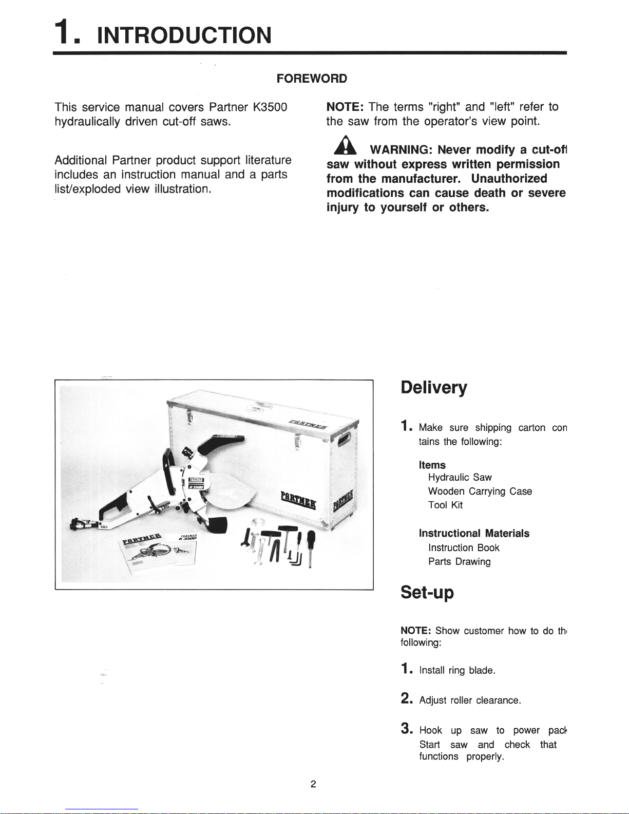
Make sure shipping carton con-
tains the following:
Items
Hydraulic Saw
Wooden Carrying Case
Tool Kit
Instructional Materials
Instruction Book
Parts Drawing
.
Set-up
NOTE:
Show customer how to do the
following:
2. Adjust roller clearance.
3. Hook up saw to power pack.
Start saw and check that it
functions properly.
2
1. INTRODUCTION
Customer Instruction
1. GENERAL
Encourage the customer to review instructional
material provided with the saw to achieve the best
performance and reliability; and to ensure safety
for himself and others.
2.
SAFETY
Follow standard safety procedures established for
any hand-held concrete saw.
Discuss proper
operating pressure and proper oil flow.
Instruct
customer on correct blade rotation.
3.
SAFETY EQUIPMENT
Go over all safety clothing and equipment that
must be used.
Stress the importance of eye
protection.
4.
CUTTING BLADES, ROLLERS, AND
DRIVE DISC
Inform the customer about matching the blade
type to the type of material to be cut. Show how
to adjust the rollers.
Give guidelines on what to
expect on roller life, drive disc life and blade life,
all of which vary with the operating technique and
the material being cut. Tell the customer, when
the blade slows or stops cutting, to first check the
condition of the drive disc before making other
adjustments. Advise him that blades are for wet
cutting, not dry cutting.
5. CONTROLS
Show the customer the correct starting position
and how the controls work when cutting. Stress
the importance of keeping all controls clean to
allow proper movement.
6.
WORKING TECHNIQUE
Demonstrate approved cutting techniques with
special emphasis on avoiding unsafe practices
such as twisting the blade in the cut. Emphasize
the importance of ample water supply on the
blade and of keeping all water nozzles free of
blockage.
7.
MAINTENANCE
Inform the customer about the maintenance which
he or the operator can perform. Stress the
importance of lubricating the engagement rollers
and checking the wear of the drive disc on a
regular basis to avoid unexpected blade slippage.
Follow maintenance schedule provided in the
Service Manual.
8. WARRANTY
Cover the information in the warranty and send in
the warranty registration card.
The warranty
covers breakdown due to defective material or
workmanship for 6 months.
3
2.
DESCRIPTION
L
.:
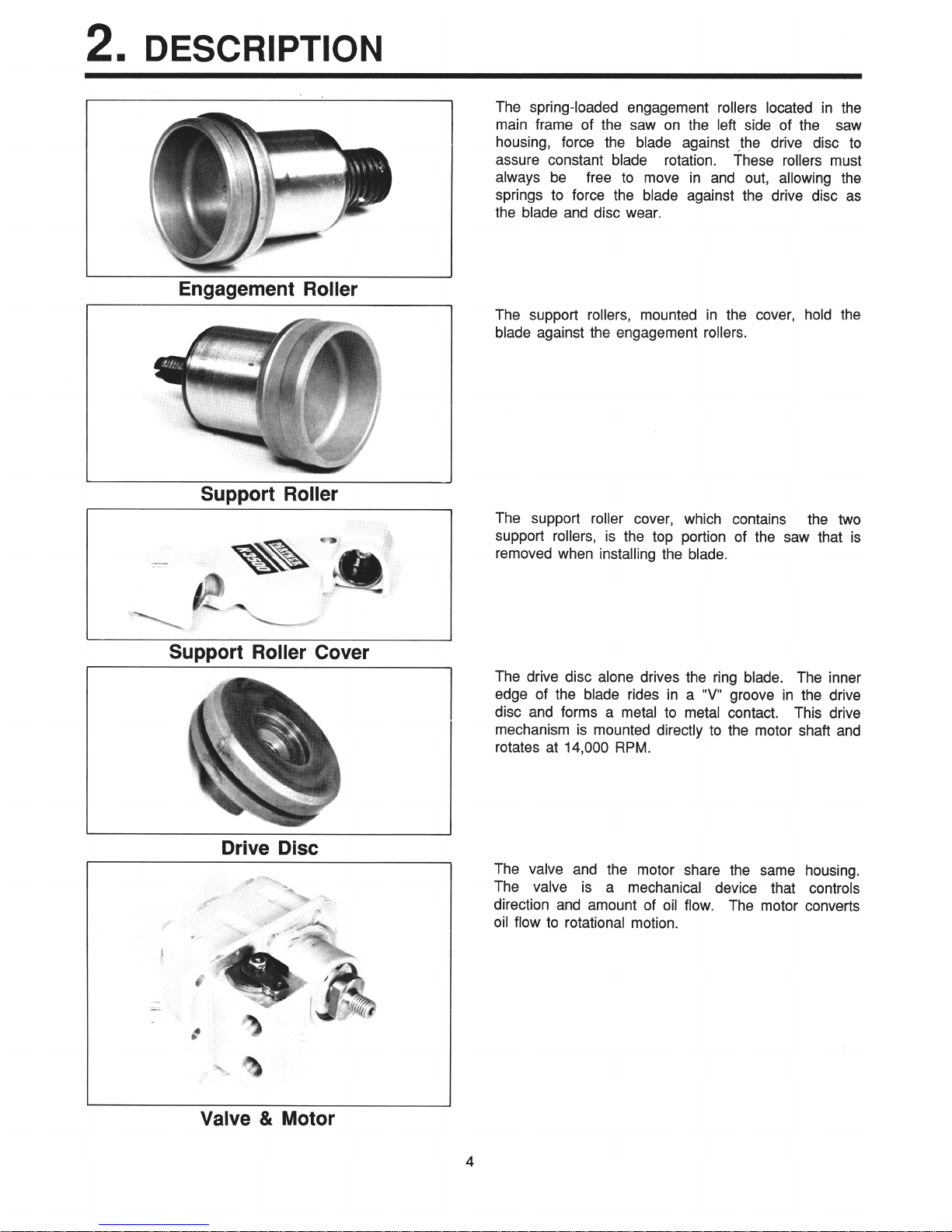
Engagement Roller
Support Roller
Support Roller Cover
L
Drive Disc
I
Valve & Motor
The spring-loaded engagement rollers located in the
main frame of the saw on the left side of the saw
housing, force the blade against the drive disc to
assure constant blade rotation.
These rollers must
always be free to move in and out, allowing the
springs to force the blade against the drive disc as
the blade and disc wear.
The support rollers, mounted in the cover, hold the
blade against the engagement rollers.
The support roller cover, which contains the two
support rollers, is the top portion of the saw that is
removed when installing the blade.
The drive disc alone drives the ring blade. The inner
edge of the blade rides in a “v” groove in the drive
disc and forms a metal to metal contact. This drive
mechanism is mounted directly to the motor shaft and
rotates at 14,000 RPM.
The valve and the motor share the same housing.
The valve is a mechanical device that controls
direction and amount of oil flow. The motor converts
oil flow to rotational motion.
4
B
2. DESCRIPTION
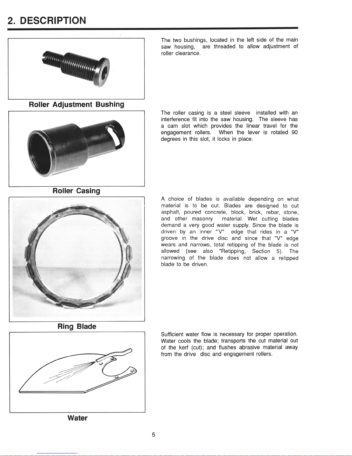
Roller Adjustment Bushing
Roller Casing
Ring Blade
The two bushings, located in the left side of the main
saw housing,
are threaded to allow adjustment of
roller clearance.
The roller casing is a steel sleeve installed with an
interference fit into the saw housing. The sleeve has
a cam slot which provides the linear travel for the
engagement rollers. When the lever is rotated 90
degrees in this slot, it locks in place.
A choice of blades is available depending on what
material is to be cut. Blades are designed to cut
asphalt, poured concrete, block, brick, rebar, stone,
and other masonry
material. Wet cutting blades
demand a very good water supply. Since the blade is
driven by an inner “V”
edge that rides in a “V”
groove in the drive disc and since that “V” edge
wears and narrows, total retipping of the blade is not
allowed (see
also
“Retipping, Section 5). The
narrowing of the blade does not allow a retipped
blade to be driven.
‘_
Sufficient water flow is necessary for proper operation.
Water cools the blade; transports the cut material out
of the kerf (cut); and flushes abrasive material away
from the drive disc and engagement rollers.
Water
5
E!!f!
3.
THEORY OF OPERATION
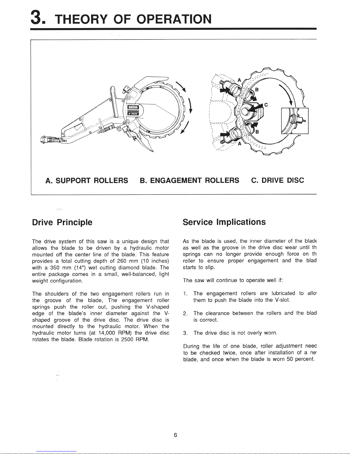
A. SUPPORT ROLLERS
B. ENGAGEMENT ROLLERS
C. DRIVE DISC
Drive Principle
Service Implications
The drive system of this saw is a unique design that
allows the blade to be driven by a hydraulic motor
mounted off the center line of the blade. This feature
provides a total cutting depth of 260 mm (10 inches)
with a 350 mm (14”) wet cutting diamond blade. The
entire package comes in a small, well-balanced, light
weight configuration.
The shoulders of the two engagement rollers run in
the groove of the blade, The engagement roller
springs push the roller out, pushing the V-shaped
edge of the blade’s inner diameter against the V-
shaped groove of the drive disc. The drive disc is
mounted directly to the hydraulic motor. When the
hydraulic motor turns (at 14,000 RPM) the drive disc
rotates the blade. Blade rotation is 2500 RPM.
As the blade is used, the inner diameter of the blade,
as well as the groove in the drive disc wear until the
springs can no longer provide enough force on the
roller to ensure proper engagement and the blade
starts to slip.
The saw will continue to operate well if:
1. The engagement rollers are lubricated to allow
them to push the blade into the V-slot.
2. The clearance between the rollers and the blade
is correct.
3. The drive disc is not overly worn.
During the life of one blade, roller adjustment needs
to be checked twice, once after installation of a new
blade, and once when the blade is worn 50 percent.
-.
6
4.
SPECIFICATIONS
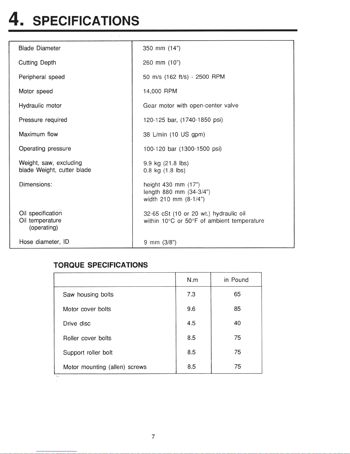
Blade Diameter
Cutting Depth
Peripheral speed
Motor speed
Hydraulic motor
Pressure required
Maximum flow
Operating pressure
Weight, saw, excluding
blade Weight, cutter blade
Dimensions:
Oil specification
Oil temperature
(operating)
350 mm (14”)
260 mm (IO”)
50 m/s (162 ft/s) - 2500 RPM
14,000 RPM
Gear motor with open-center valve
120-125 bar, (1740-1850 psi)
38 L/min (10 US gpm)
100-l 20 bar (1300-1500 psi)
9.9 kg (21.8 Ibs)
0.8 kg (1.8 Ibs)
height 430 mm (17”)
length 880 mm (34-3/4”)
width 210 mm (8-l/4”)
32-65 cSt (10 or 20 wt.) hydraulic oil
within 10% or 50°F of ambient temperature
Hose diameter, ID
9 mm (3/8”)
TORQUE SPECIFICATIONS
Saw housing bolts
7.3
Motor cover bolts
9.6
Drive disc
4.5
Roller cover bolts
8.5
Support roller bolt
8.5
Motor mounting (allen) screws
8.5
N.m in Pound
I
7
B
5. SET-UP & ADJUSTMENTS
A. BLADE...
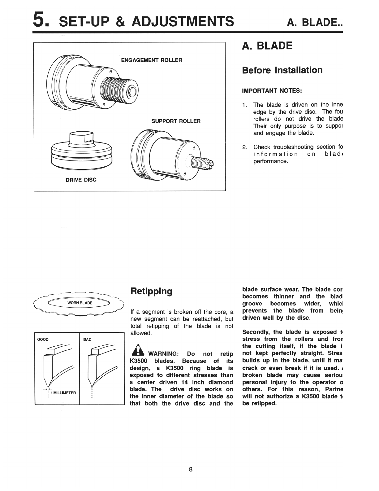
ENGAGEMENT ROLLER
SUPPORT ROLLER
DRIVE DISC
--
Retipping
WORN BLADE
.-.
OD BAD
If a segment is broken off the core, a
new segment can be reattached, but
total retipping of the blade is not
allowed.
a
WARNING:
Do not retip
K3500 blades.
Because of its
design,
a K3500 ring blade is
exposed to different stresses than
a center driven 14 inch diamond
blade. The
drive disc works on
the inner diameter of the blade so
that both the drive disc and the
A. BLADE
Before Installation
IMPORTANT NOTES:
1. The blade is driven on the inner
edge by the drive disc. The four
rollers do not drive the blade.
Their only purpose is to support
and engage the blade.
2. Check troubleshooting section for
information on
blade
performance.
blade surface wear. The blade core
becomes thinner and the blade
groove becomes wider, which
prevents the blade from being
driven well by the disc.
Secondly, the blade is exposed to
stress from the rollers and from
the cutting itself, If the blade is
not kept perfectly straight. Stress
builds up in the blade, until it may
crack or even break if it is used. A
broken blade may cause serious
personal injury to the operator or
others. For this reason, Partner
will not authorize a K3500 blade to
be retlpped.
8
5. SET-UP & ADJUSTMENTS
. ..A. BLADE...
4D
9
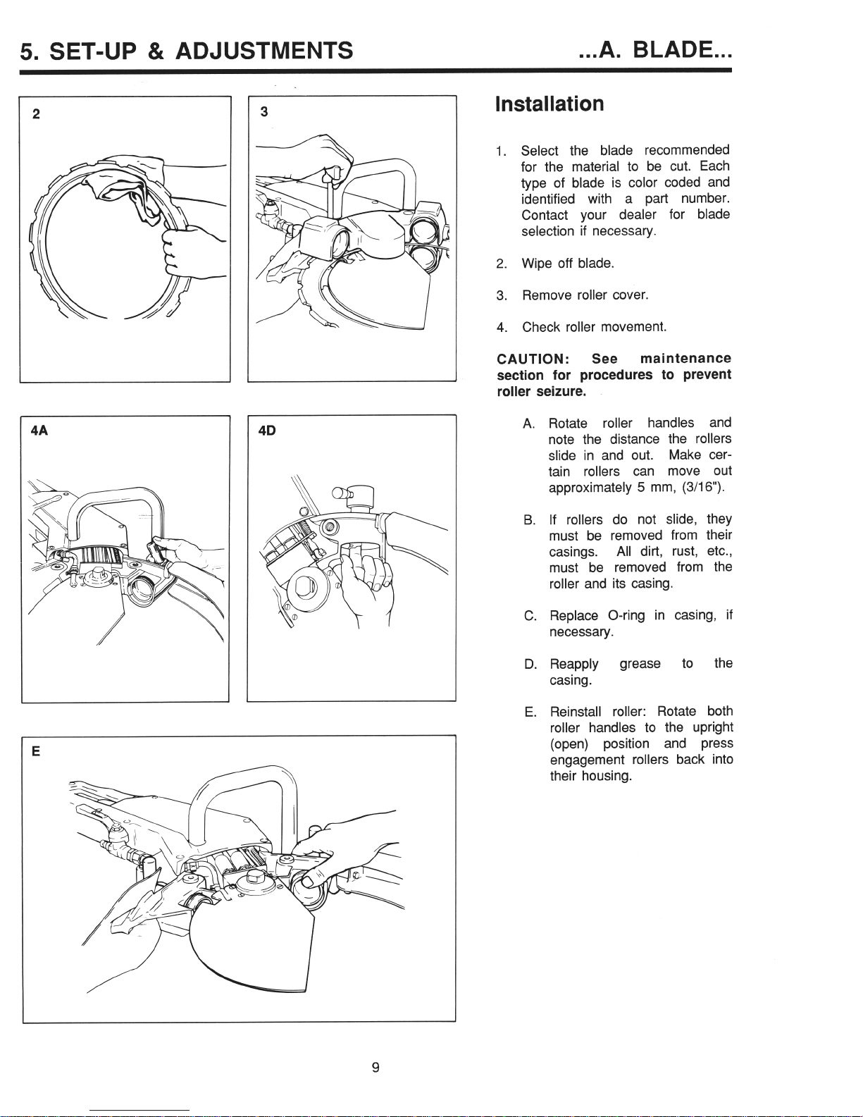
Installation
1. Select the blade recommended
for the material to be cut. Each
type of blade is color coded and
identified with a part number.
Contact your dealer for blade
selection if necessary.
2. Wipe off blade.
3. Remove roller cover.
4. Check roller movement.
CAUTION:
See
maintenance
section for procedures to prevent
roller seizure.
A. Rotate roller handles and
note the distance the rollers
slide in and out. Make certain rollers can move out
approximately 5 mm, (3/16”).
B. If rollers do not slide, they
must be removed from their
casings.
All dirt, rust, etc.,
must be removed from the
roller and its casing.
C. Replace O-ring in casing, if
necessary.
D. Reapply grease to
the
casing.
E. Reinstall roller: Rotate both
roller handles to the upright
(open) position and press
engagement rollers back into
their housing.
r’
.\
5. SET-UP & ADJUSTMENTS
. ..A. BLADE 1:::
6
10
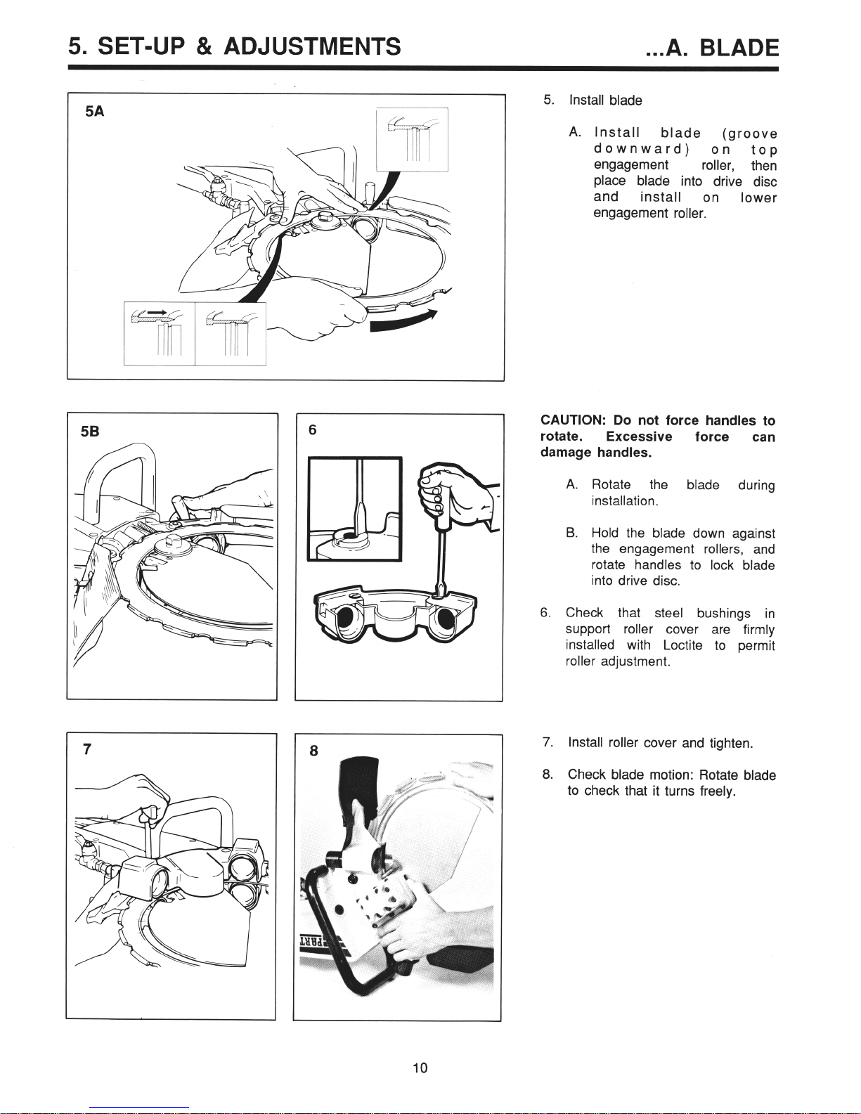
5. Install blade
A. Install
blade (groove
downward) on
top
engagement
roller, then
place blade into drive disc
and
install on
lower
engagement roller.
CAUTION: Do not force handles to
rotate.
Excessive force can
damage handles.
A. Rotate the blade during
installation.
B. Hold the blade down against
the engagement rollers, and
rotate handles to lock blade
into drive disc.
6. Check that steel bushings in
support roller cover are firmly
installed with Loctite to permit
roller adjustment.
7. Install roller cover and tighten.
8. Check blade motion: Rotate blade
to check that it turns freely.
5. SET-UP & ADJUSTMENTS B. ROLLER...
r
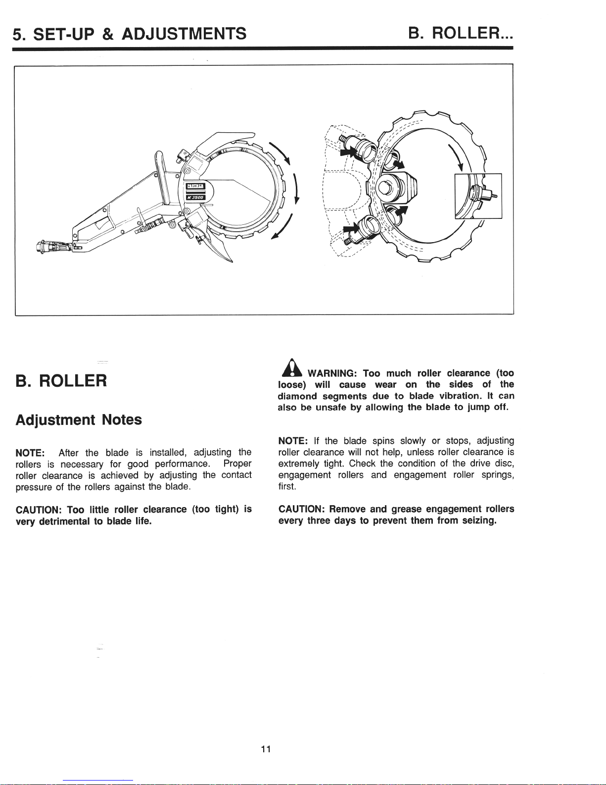
B. ROLLER
Adjustment Notes
NOTE:
After the blade is installed, adjusting the
rollers is necessary for good performance.
Proper
roller clearance is achieved by adjusting the contact
pressure of the rollers against the blade.
CAUTION: Too little roller clearance (too tight) is
very detrimental to blade life.
a
WARNING: Too much roller clearance (too
loose) will cause wear on the sides of the
diamond segments due to blade vibration. It can
also be unsafe by allowing the blade to jump off.
NOTE: If the blade spins slowly or stops, adjusting
roller clearance will not help, unless roller clearance is
extremely tight. Check the condition of the drive disc,
engagement rollers and engagement roller springs,
first.
CAUTION: Remove and grease engagement rollers
every three days to prevent them from seizing.
11

5. SET-UP & ADJUSTMENTS
. ..B. ROLLER...
Adjustment
Checking Roller Clearance
It is recommended that the following
procedure be demonstrated to the
user. Once the proper roller clearance
is experienced, the use of a pull
scale and vise-grip pliers may not be
necessary.
1. Grip one support
+ a time
v i/
r
Excessive tension can
,rlse blade to warp.
4. Move vise-grip pliers to the
bottom support roller and check
in the same manner as the top
support roller.
Adjust roller
clearance so that clearance of
both rollers is the same.
Example:
Setting may vary between 4565N
(lo-14 Ibs.), but must be the
same within 4.5N (1 lb.) on both
upper
and lower
roller.
For
example, if the upper roller is
50N (11 Ibs.) the lower roller
must be 50N f 4.5N (11 + 1 lb.).
12
5. SET-UP & ADJUSTMENTS
. ..B. ROLLER...
INCREASING
ROLLER CLEARANCE
DECREASING
ROLLER CLEARANCE
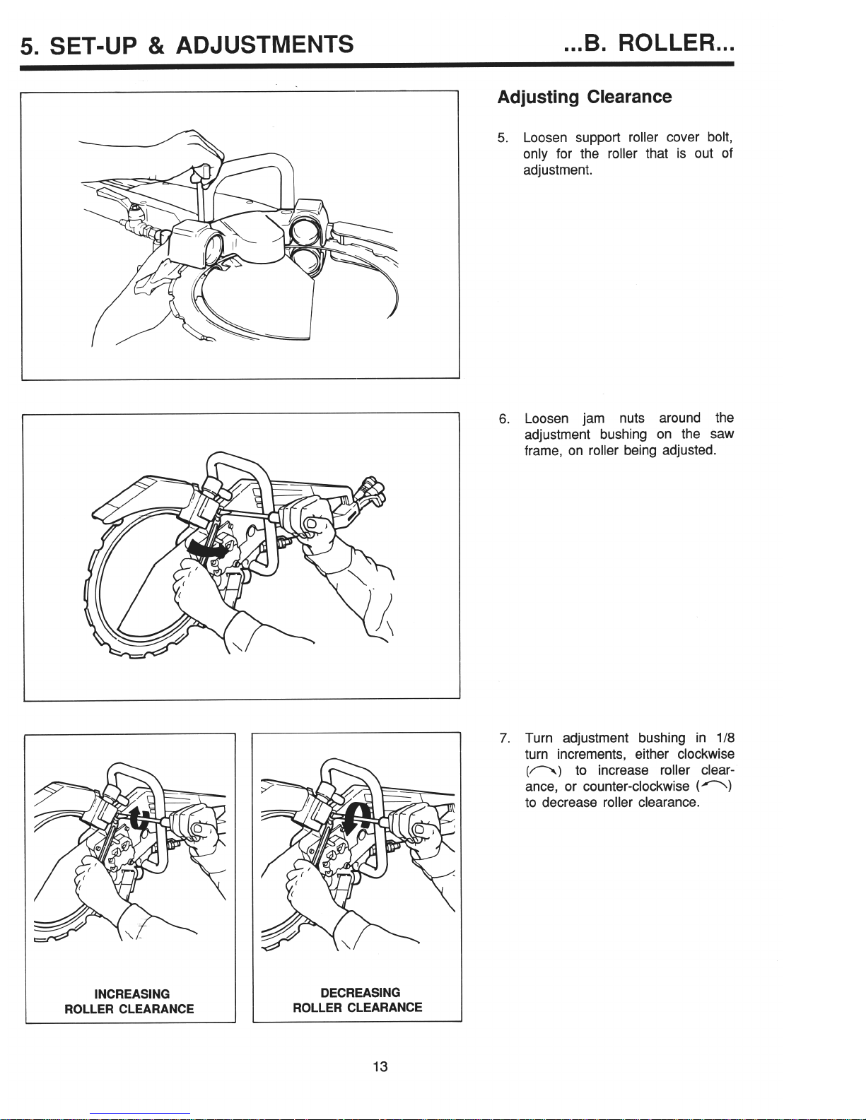
Adjusting Clearance
5. Loosen support roller cover bolt,
only for the roller that is out of
adjustment.
6. Loosen jam nuts around the
adjustment bushing on the saw
frame, on roller being adjusted.
7. Turn adjustment bushing in 118
turn increments, either clockwise
(n) to increase roller clearance, or counter-clockwise (n)
to decrease roller clearance.
13
5. SET-UP & ADJUSTMENTS
. ..B. ROLLER...
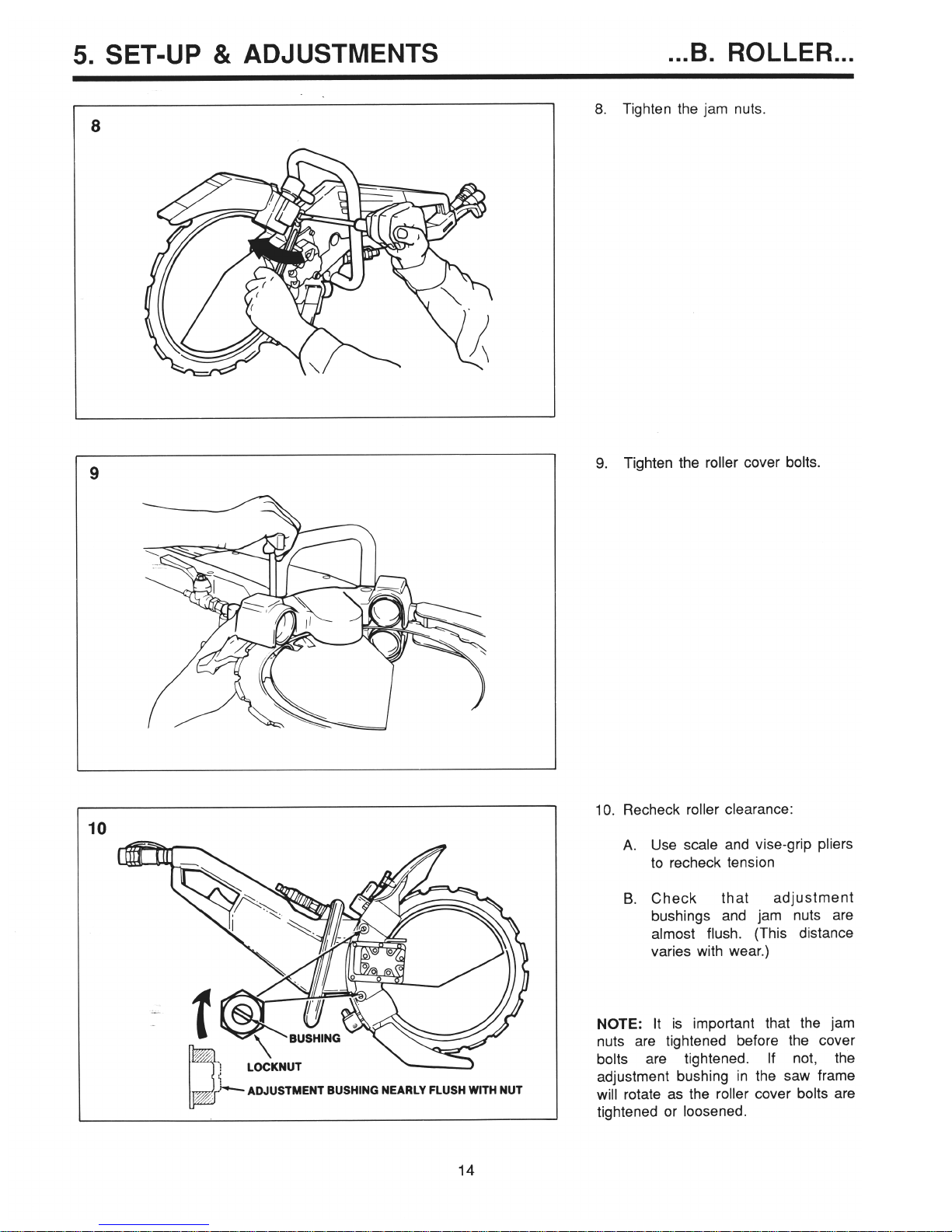
lmf-
ADJUSTMENT BUSHING NEARLY FLUSH WITH NUT
8. Tighten the jam nuts
9. Tighten the roller cover bolts.
10. Recheck roller clearance:
A. Use scale and vise-grip pliers
to recheck tension
B. Check that adjustment
bushings and jam nuts are
almost flush. (This distance
varies with wear.)
NOTE: It is important that the jam
nuts are tightened before the cover
bolts are tightened. If not, the
adjustment bushing in the saw frame
will rotate as the roller cover bolts are
tightened or loosened.
14
&?!!!!I
. ..B. ROLLER
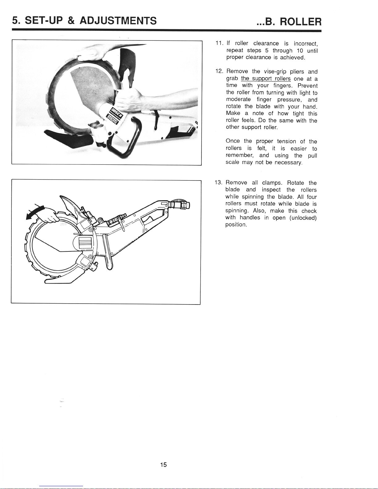
11. If roller clearance is incorrect,
repeat steps 5 through 10 until
proper clearance is achieved.
12.
Remove the vise-grip pliers and
grab the support rollers one at a
time with your fingers. Prevent
the roller from turning with light to
moderate finger pressure, and
rotate the blade with your hand.
Make a note of how tight this
roller feels. Do the same with the
other support roller.
Once the proper tension of the
rollers is felt, it is easier to
remember,
and using the pull
scale may not be necessary.
13. Remove all clamps. Rotate the
blade and inspect the rollers
while spinning the blade. All four
rollers must rotate while blade is
spinning. Also, make this check
with handles in open (unlocked)
position.
15

5. SET-UP & ADJUSTMENTS
C. DRIVE DISC
C. DRIVE DISC
NOTE: If the blade slows or stops
momentarily while cutting, the drive
disc should be one of the first items
inspected for wear. The drive disc is
an expendable item and needs to be
replaced on a regular basis.
1. With the 8 mm, 5/16” allen
wrench, remove support
roller
cover and blade from machine.
NOTE:
Drive disc has a left-hand
thread
A
2. With the two 19 mm wrenches,
; . . ‘..
remove drive disc from saw
motor shaft.
3. Look across the driving edge of
drive disc and inspect for wear.
If the driving surface is too badly
worn, the inner edge of the blade
will “bottom out” in the drive disc
and slippage of the blade will
result. Replace as needed.
Assembly Notes:
A. Grease drive disc thread.
B. Replace O-rings (on later
models) if needed.
C. Tighten drive disc to 4.5 N.m
(40 in. lb.)
16
6.
SERVICE
A. ROLLER SYSTEM...
‘,
OLLER CLAMP
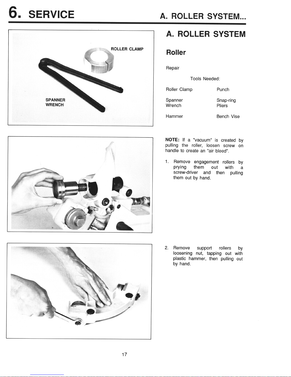
A. ROLLER SYSTEM
Roller
Repair
Tools Needed:
Roller Clamp
Punch
Spanner
Wrench
Snap-ring
Pliers
Hammer
Bench Vise
NOTE: If a “vacuum” is created by
pulling the roller, loosen screw on
handle to create an “air bleed”.
1. Remove engagement rollers by
Prying
them out
with a
screw-driver and then pulling
them out by hand.
2. Remove
support
rollers by
loosening nut, tapping out with
plastic hammer, then pulling out
by hand.
17
 Loading...