

Page 1

PN. 772231701
[©2013 ParTech, Inc. All rights reserved.]
PAR POS Installation Manual
for TACO DEL MAR®
ES7700
Page 2

This material has been created in order to accommodate a wide range of restaurant operations and your specific
business practices and system configuration may differ slightly from what is represented in this material. While
ParTech, Inc. takes great care to ensure the accuracy of these materials, all material is provided without warranty
whatsoever, including, but not limited to, the implied warranties of merchantability or fitness for a particular
purpose.
Trademark Notices: ParTech, the PAR logo, Boundless Hospitality™ and PAR EverServ POS QSR Edition, TSR Edition,
PixelPoint Edition, ES7700, EverServ 2000, and EverServ Kiosk 6000 are all trademarks of PAR Technology
Corporation, the parent company of ParTech, Inc. All other product names and services used throughout this
material are trademarks or registered trademarks of their respective companies. The product names and services
are used in an editorial fashion only and for the benefit of such companies. No such use of any trade name is
intended to convey endorsement or other affiliation with these materials.
Reproduction: Copyright © 2013 ParTech, Inc. All rights reserved. This publication, or any part thereof, may not
be reproduced or transmitted in any form or by any means, electronic or mechanical, including photocopying,
recording, storage in an information retrieval system, or otherwise, without the prior written permission of
ParTech, Inc., PAR Technology Park, 8383 Seneca Turnpike, New Hartford, NY 13413-4991; Phone: (315) 738-0600.
Copyright© 2013 ParTech, Inc. All rights reserved.
Page 3

Table of Contents
Chapter 1: Getting Started................................................................................................................. 1
Overview ................................................................................................................................................... 1
Inventory Equipment ................................................................................................................................ 1
How to Use this Manual ........................................................................................................................... 3
Pre-Installation Guidelines ....................................................................................................................... 3
POS Terminal Electrical Requirements ..................................................................................................... 3
Size and Type of Electrical Service ............................................................................................................ 3
LAN Cable Considerations ........................................................................................................................ 4
Chapter 2: Installing the PAR ES7700® POS System ........................................................................... 6
Overview ................................................................................................................................................... 6
Prepare POS Terminal for Setup ............................................................................................................... 6
Remove Covers to Access Connection Panels .......................................................................................... 7
Set Up K7552 Zoom Modem – Optional ................................................................................................... 8
Set Up Network Connection ................................................................................................................... 12
Connect your System to the Internet ..................................................................................................... 13
Verify all Cables are Connected to the Terminal .................................................................................... 16
Gather the Cables and Replace Cable Retainers .................................................................................... 16
Install Pedestal Cover and I/O Panel ...................................................................................................... 16
Connect POS Components to UPS .......................................................................................................... 17
Power on the POS Equipment ................................................................................................................ 18
Cleaning the POS Terminal ..................................................................................................................... 18
Chapter 3: Pre-Go Live Setup Instructions ........................................................................................ 20
Step 1: Starting up System ..................................................................................................................... 20
Step 2: Log into Pixel Back Office ........................................................................................................... 20
Step 3: Verify System Taxes .................................................................................................................... 21
Step 4: Verify Company Information ...................................................................................................... 21
Step 5: Verify System Prices ................................................................................................................... 21
Step 6: Add Owner to the System .......................................................................................................... 21
Step 7: Add Employees to the System .................................................................................................... 22
Step 8: Verify Receipt Setup ................................................................................................................... 22
Important notes:..................................................................................................................................... 22
Chapter 4: Troubleshooting ............................................................................................................. 23
M3873-61V Printer Troubleshooting Steps ............................................................................................ 23
Cash Drawer Troubleshooting Steps ...................................................................................................... 24
Register Troubleshooting ....................................................................................................................... 25
UPS Troubleshooting .............................................................................................................................. 27
Page 4
Chapter 1:
Who to Call – PAR Help Desk 800-382-6200
For GoLive questions or to reschedule your GoLive date, please call our PAR Help Desk and
ask to leave a message for a PAR GoLive Specialist. Or you can send an e-mail to the
[email protected] mailbox.
If you identify any PAR hardware is not working, call the Help Desk immediately
When your store is open for operations, please call the PAR Help Desk for all your technical
questions
For changes to your menu you should call the help desk and they will route your request to
the Menu Maintenance group. Please keep in mind that you will manage your price changes
but the Menu Maintenance team can assist with additions or fixes for your menu, inventory
or discounts.
Getting Started
In this chapter, you will perform the following steps:
Gather information to complete the installation of your new Point-of-Sale (POS) system.
Inventory the POS equipment in your order and verify the contents of the order are correct.
Review Pre-Installation guidelines
Overview
It is important to understand that installing a POS system is a large task, and while this document will
guide you step-by-step through the process, you must set aside the time to follow the guide closely and
carefully. Give yourself plenty of time and space to complete your POS installation.
If you have any questions while installing your POS system, contact the PAR Help Desk at 1-800-382-
6200.
Inventory Equipment
Prior to installing your new PAR EverServ™ POS system, ensure you have received all the equipment
needed by comparing the items in your shipment to the items listed on the shipping document. If the
equipment shipped does not match the shipping document, contact PAR Order Administration at 1-800-
448-6505.
Page 1
Page 5
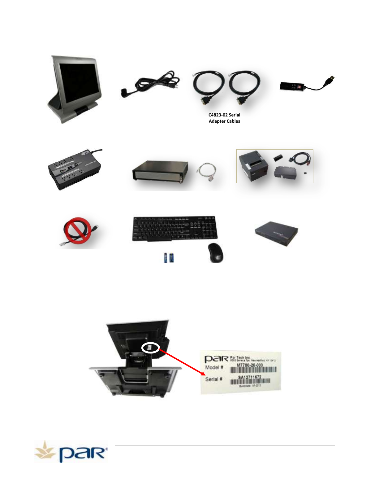
Below are the examples of what you should have in your inventory:
M3557 Tripp Lite
Uninterruptible Power Supply
M8570-03 Cash Drawer with Interface cable
K4300-03 Netgear Router
EverServ 7000 M7700 POS
AC Power Cord
C4823-02 Serial
Adapter Cables
M3873-61V Epson (TM-T88V)
Printer with Interface Cable
K3244 Wireless Mouse, Keyboard and batteries
Cable that comes with M3557 –
do not use
K7552 Zoom Modem
(Optional)
Model and Serial Information and Location
Locate the model/serial number sticker, as shown below. You may need the information on the sticker
when speaking with the help desk.Tilt the head of the register back horizonally and lay the register on its
back.
Page 2
Page 6
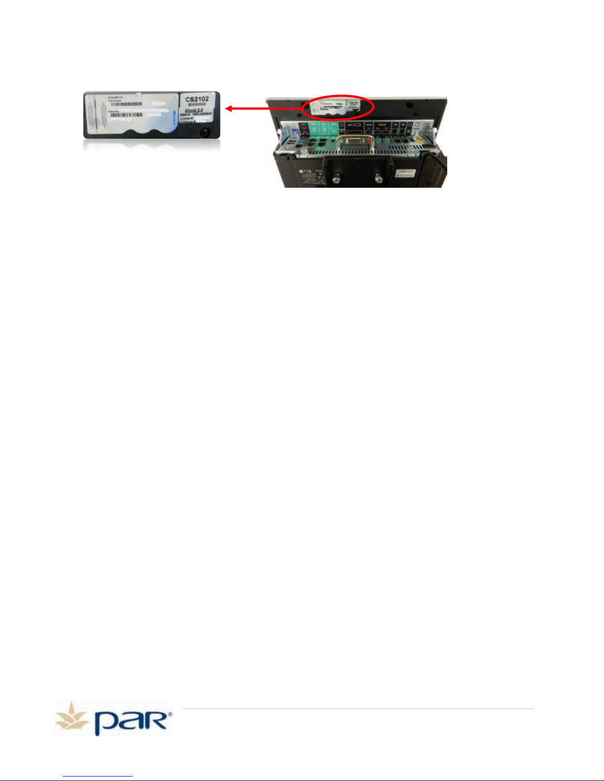
Windows License Sticker Location
For the Windows license sticker, look here:
How to Use this Manual
This manual provides step-by-step instructions for installing your ES7700 POS terminals and
peripherals. Review this manual completely before attempting to install your system. Chapter 1
provides guidelines and general information for the install.
Chapter 2 of this guide provides setup instructions for your POS terminals and peripherals. If you
receive a second terminal you will complete the steps in Chapter 2 twice – once for Station 1 and
once for Station 2.
Chapter 3 of this guide provides the setup instructions for your POS system. You will enter your site
information, taxes, employees and other Pre-Training information to start using your POS system.
Pre-Installation Guidelines
Before installing your new PAR EverServ™ POS system, you must ensure certain pre-installation
guidelines are followed to protect your equipment, your store, and your employees. If you have any
questions regarding the following guidelines, contact your PAR sales representative Mike Hatcher at
1-800-458-6898 Ext. 5873 and e-mail at [email protected]. If your store requires
additional electrical wiring or network cabling, you may need to contact an electrical contractor to
perform this work.
POS Terminal Electrical Requirements
120 VAC power (meets NEC requirements)
Dedicated circuit for POS
UPS for POS terminals (provided with POS system purchase)
Size and Type of Electrical Service
In the USA and Canada, power must be 120 VAC, 60 Hz, single-phase, 3-wire. In other countries,
power may be 240 VAC, 50 Hz, single-phase, 3-wire. Voltage tolerances: 104-127 VAC for nominal
120 VAC, and 208-255 VAC for nominal 240 VAC. Most installations require a single 15-amp circuit
breaker. Whenever possible, put all POS receptacles on the same breaker. If additional circuit
breakers are required, make sure they are on the same phase as the first breaker.
Page 3
Page 7
LAN Cable Considerations
K4300-03 NETGEAR VPN Firewall
LAN IP: 192.168.0.1
Broadband Providers Modem/Router/WAP
(Configured as – DHCP)
(Supported by Broadband provider)
PAR POS System
Internal “Private” Network
External “PUBLIC” Network
Optional Customer Supplied and
Supported WAP
(isolated from POS)
UPS
Station 2
(optional)
Station 1
Internet
UPS
(optional)
Legend
UPS Power Connection:
LAN Connection:
Other concept Internal
“Private” Network
UPS
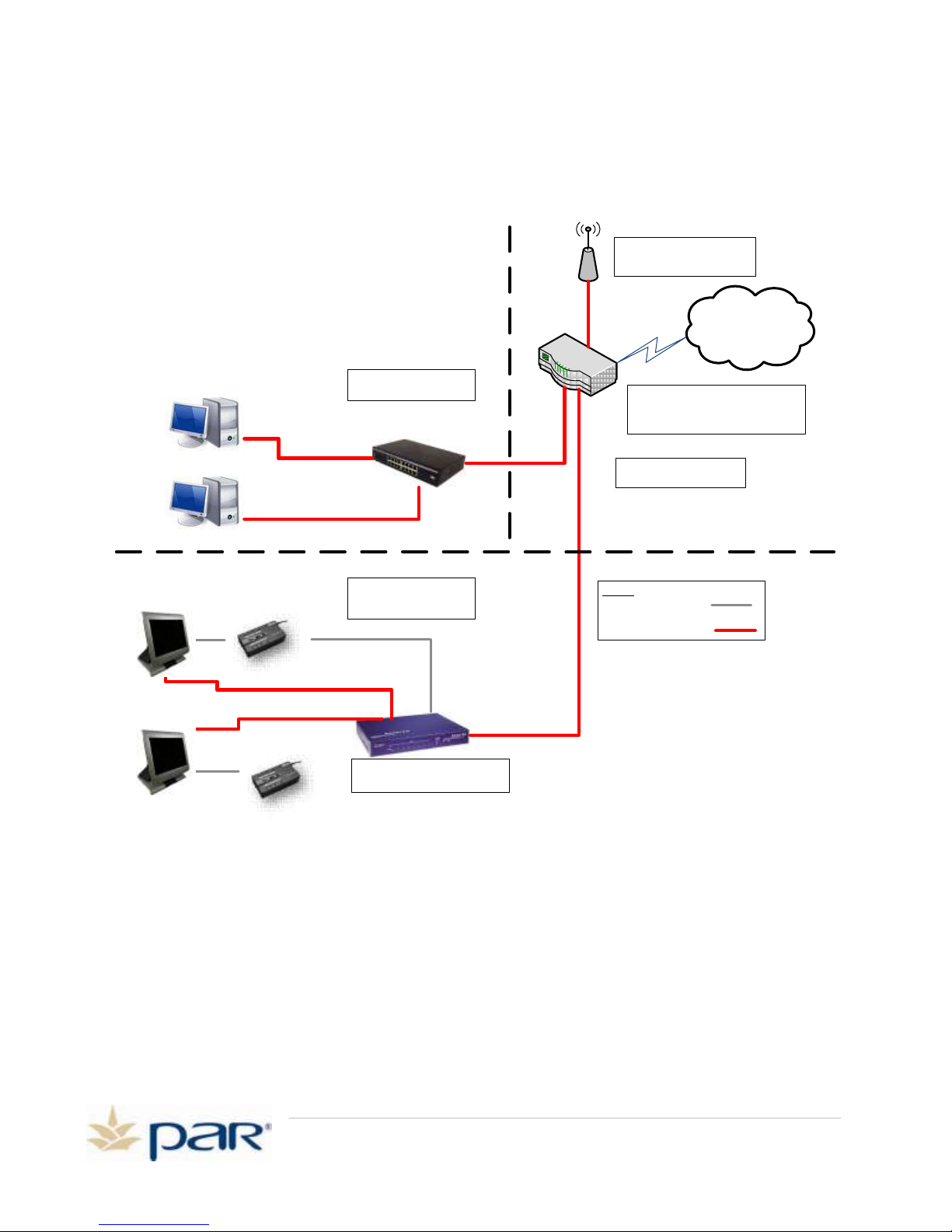
EverServ POS terminals typically communicate with the other registers in the store and to the outside
world over a local area network (LAN). This is accomplished by connecting a four-pair CAT5e cable
from the POS terminal’s LAN port in the cable well to the K4300-03 Netgear router and the stores
DSL/Router. The typical TACO DEL MAR LAN configuration is shown below.
Please remember the general rules listed below for LAN cable installation:
LAN Cables must be placed inside conduits whenever possible. Some conduit
may be shared by other store cabling but not AC power. Do not run the LAN
cable in the same conduit as AC power.
Never run LAN cables on the floor. Use a cable chase to protect the cables.
LAN Cable should not be routed near power sources or over light fixtures.
If tie-wraps are used to bundle LAN cables, the tie-wraps should be tightened
to the point of just snug. Do not over tighten the tie-wrap.
Excess cable must be tie-wrapped so that it never lies on the floor.
Page 4
Page 8

The recommended maximum distance of the horizontal link (home run and
patch cables) should not exceed 325 feet: 295 for the home run and 30 feet
split between the ends of the home run cable.
Do not put sharp bends into individual wire pairs when terminating.
Cables that have been bent or kinked beyond the acceptable bend radius
cannot be straightened to correct a problem. Cables should not be bent tighter
than ½ inch radius, or about the size of a quarter.
Untwisting of pairs when making a termination should not exceed ½ inch.
Limit the amount of cable insulation stripped to protect the pairs from
untwisting or separating.
Limit the amount of twisting on the cable. Excessive twisting can cause the
separation of the individual pairs.
Use an adequate amount of hangers when suspending Cat5e cables to avoid
cable stress.
Page 5
Page 9
PAR POS Installation Manual for TACO DEL MAR
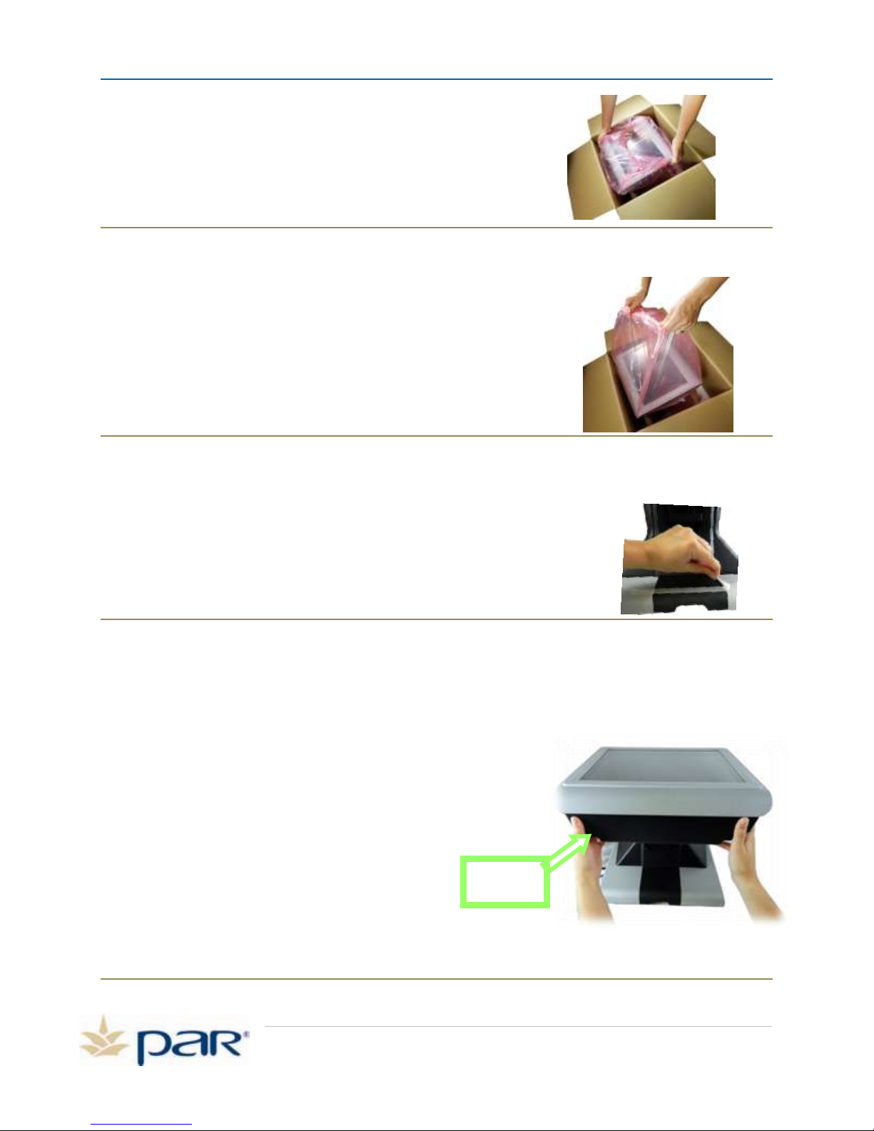
Figure 2: Removing the POS from the box
Chapter 2:
Installing the PAR
ES7700® POS System
Topics covered in this chapter:
Setting up your ES7700 POS terminal and peripherals (receipt printer, cash drawer, keyboard, mouse,
UPS, and router). The typical store configuration will consist of one terminal called Station 1. If the
store has a drive-thru then there may be 2 terminals, and the second terminal will be called Station 2.
Overview
The procedures in this chapter outline how to install your ES7700 POS terminal and peripherals.
1. Verify receipt and condition of all boxes and components. Verify physical site and power
availability is adequate.
2. Verify the product numbers match the shipping list. If it is not a match, or if any items are
missing or damaged, contact PAR Order Administration at 1-800-448-6505.
Prepare POS Terminal for Setup
Remove POS from Box
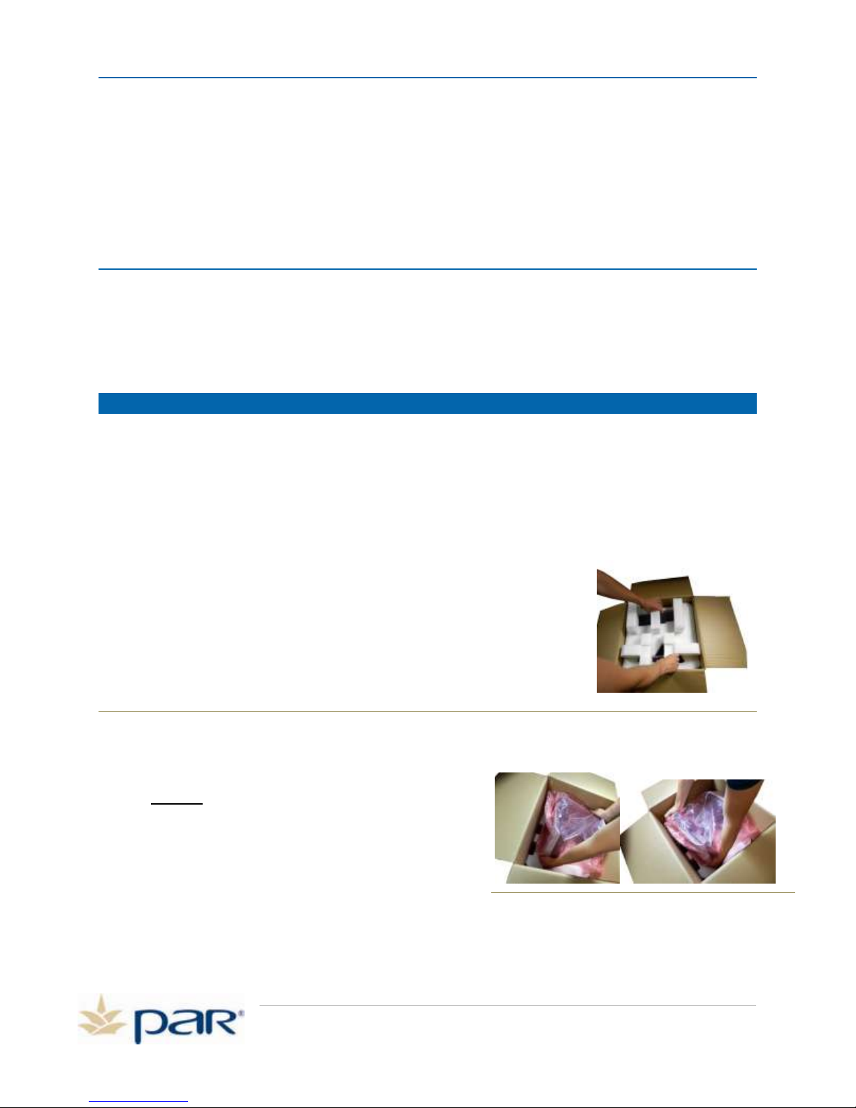
3. The POS terminal is located in Box 1. Open the box and remove the
Styrofoam end cap, shown in Figure 1.
Figure 1: Removing end cap
4. Put your left hand on the left side of the top and
tilt it to the right, shown in Figure 2.
DO NOT pull the POS terminal out of the box by
lifting on the antistatic bag. This may result in
damage to the terminal.
5. Firmly grasp the POS on both sides and then lift
upward, shown in Figure 2.
Page 6
Page 10
PAR POS Installation Manual for TACO DEL MAR
Remove I/O
Panel Cover
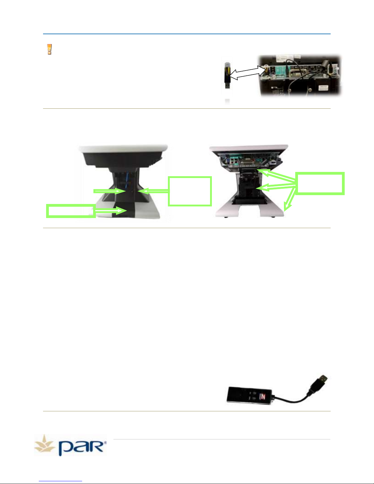
6. Move the POS so it is upright in the box, shown in Figure 3.
7. Pull the anti-static bag off the POS, shown in Figure 4.
Figure 3: Removing the POS from the box
Figure 4: Removing the anti-static bag
8. Lift the POS out of the box by grasping the sides of the head firmly.
9. Set the POS terminal upright on a flat clean surface.
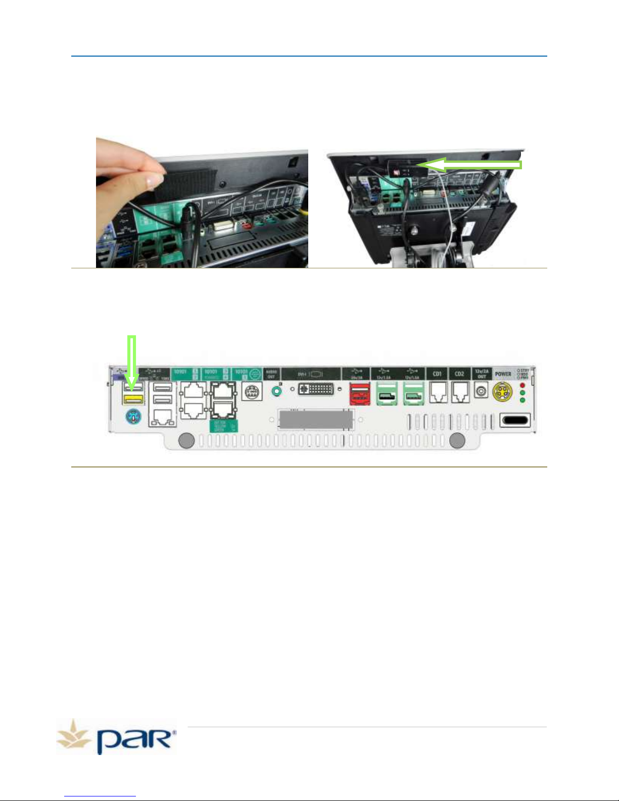
10. Remove the tape that is covering the cut out, shown in figure 5.
You are now ready to begin setting up your terminal.
Remove Covers to Access Connection Panels
NOTE: If you have ordered the K7552 Zoom modem and gray telephone cable, you
will see these attached to the POS terminal. We will set these up later.
1. Tilt the display head horizontally to the table to access
cable well covers.
2. Remove the cable well cover by pressing the two side tabs,
and pulling it away from the register
Figure 5: Pull the tape off the cut-out
Page 7
Figure 6: Remove I/O Panel Cover
Page 11
PAR POS Installation Manual for TACO DEL MAR
Loosen thumb
screws and pull
panel forward
Lift out cutout
Unclip retaining
Clamps
Note: On Station 1 you will see a black or yellow Pixel License key.
Ensure this key is securely connected to the USB port. This
looks like a USB thumb drive. See Figure 7.
Also, on Station 1 only you will see the F7552 Zoom modem, if
your store ordered it, and gray telephone cable. We will set
these up later.
Figure 7: Pixel Key Inserted, Pixel Key with Tape, Pixel Key Alone
3. Loosen the two thumb screws on the pedestal cover and slide out toward the front of the
register.
Figure 8: Loosen two thumb screws
4. Lift the cut out at the base and by lifting upward and pulling forward. This will allow easy access
when routing the peripheral cables.
5. Unclip the retaining clamps to access cables. Your ES7700 POS terminal has cable retainers
located in the pedestal and on the bottom of the pedestal for securing your cables in place to
keep them neat and organized and prevent unintentional disconnection. A cable retainer is
located in the middle of the pedestal, a second cable retainer has been added under the top
cover and three more are located in the base of the unit.
Now you have complete access to the connection ports on the POS terminal.
Set Up K7552 Zoom Modem – Optional
If the store ordered the optional K7552 Zoom modem, this will be set up now. The Zoom Modem
provides connection to the Internet via Dial-Up connection. If your store uses a high-speed (Broadband)
Internet connection, the Zoom modem acts as a back-up if the high-speed connection fails.
1. Peel the backing off of the Velcro material on the K7552 Zoom modem (optional) and apply the
modem to the bottom of the top cover as shown on
the following page.
Page 8
Figure 9: K7552 Zoom Modem (Optional)
Page 12
PAR POS Installation Manual for TACO DEL MAR
Zoom
Modem
2. Position the modem and Velcro on the top cover far enough inward and to the right so the I/O
panel can be in installed.
Figure 10: Install USB Modem
3. Plug the modem USB cable into one of the open USB ports on the left side of the cable well.
Figure 11: Plug USB Modem cable
4. Un-wrap the twist tie that secures the telephone cable.
5. Uncoil the telephone cable. We will connect this to the UPS later.
6. Next, route the network cable down the pedestal and connect the cable to your router or
switch. Contact your high-speed Internet provider for assistance if needed.
Connect Wireless Mouse and Wireless Keyboard to POS
1. Remove the mouse, keyboard and batteries from their packaging.
2. Remove the battery cover on the keyboard and install the AA battery and install the battery
cover. Take care when installing the battery to match the polarity on the battery with the
diagram inside the battery compartment.
Page 9
Page 13
PAR POS Installation Manual for TACO DEL MAR
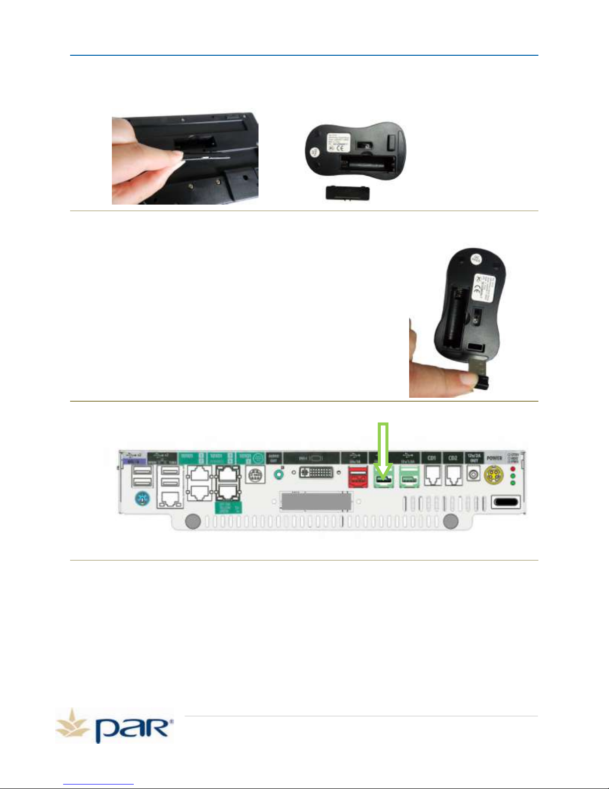
NOTE: The wireless mouse is part of the same kit as the wireless keyboard, K3244.
Figure 12: K3244, Keyboard Battery Cover (left) wireless mouse (right)
3. Remove the battery cover from the mouse.
4. For the wireless mouse, the wireless adapter is found outside the
battery compartment. See Figure 13. The wireless adapter will
be plugged into the +12V USB port shown in Figure 14.
Figure 13: Remove USB Dongle from wireless mouse
Figure 14: Install USB Dongle
5. Install one AA battery for the wireless mouse and install the battery cover. Take care when
installing the batteries to match the polarity on the battery with the diagram inside the battery
compartment.
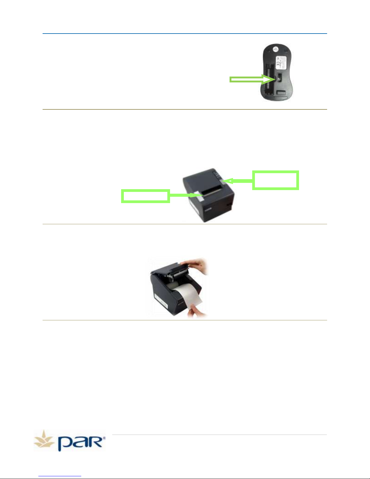
Note: The wireless mouse has a RED light which will turn on automatically when the mouse is
on, and automatically shuts off when the mouse isn’t being used. See Figure 15.
Page 10
Page 14
PAR POS Installation Manual for TACO DEL MAR
Remove Tape
Press to Open
Cover
Power LED
Figure 15: Mouse Power Switch
Connect Receipt Printer to POS
1. Remove the tape from the printer cover.
2. Open the printer cover by pressing the gray button on the right top side of the printer.
Figure 16: Remove the tape from the printer cover
3. Follow the instructions on the inside of the printer cover to load the paper.
Figure 17: Load the paper
4. Close the printer cover.
5. Locate the USB cable that came with the printer.
6. Connect the USB cable to the printer as shown below.
7. Install the cable shroud on the printer as shown in Figure 18. This protects the cable
connection.
Page 11
Page 15
PAR POS Installation Manual for TACO DEL MAR
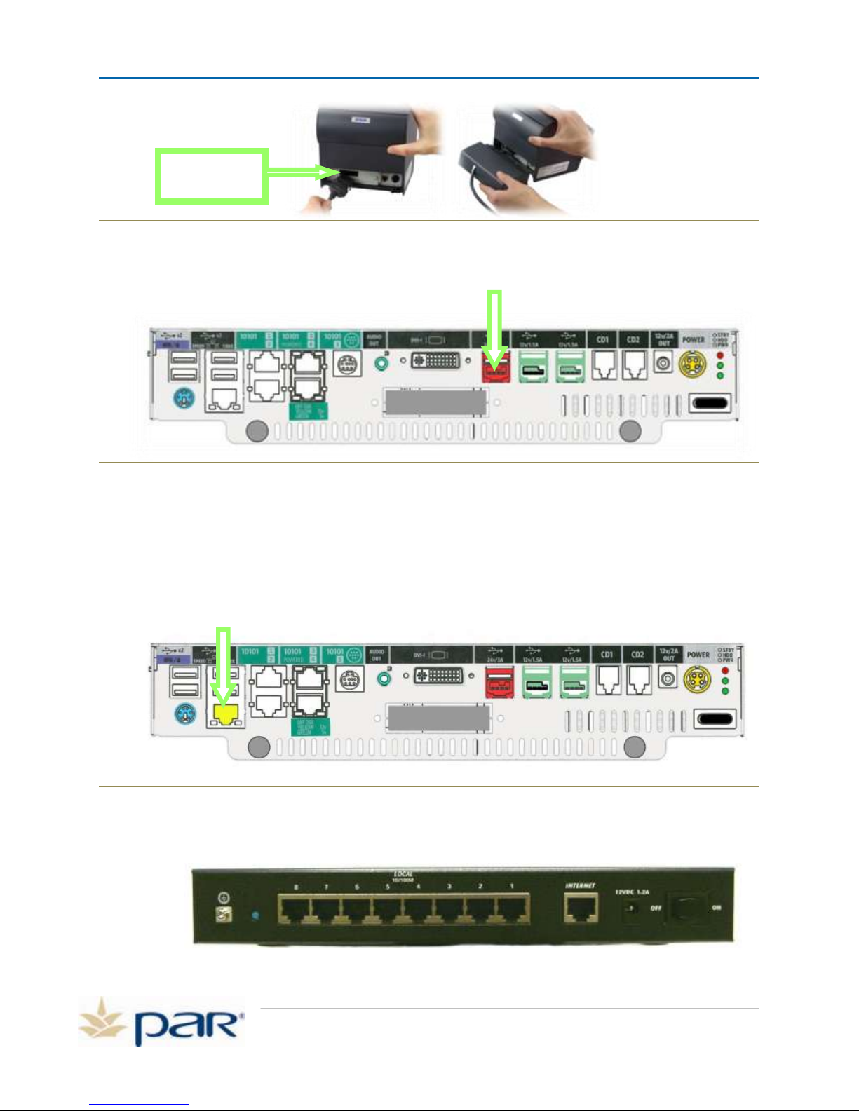
Connect the USB
cable to the printer
Figure 18: Install the cable shroud on the printer
8. Connect the other end of the USB printer cable, also shaded reddish-orange, into the reddish-
orange powered-USB port on the POS shown in the diagram on the next page.
Figure 19: Printer cable port highlighted
Set Up Network Connection
If your store does not have a high-speed connection to the Internet, proceed to “Connect Your Cash
Drawer Cable to the POS.”
1. Connect your Ethernet cable to the network port on the main cable well. The network port is
highlighted yellow in the graphic below.
Figure 20: LAN Port highlighted
2. Route the Ethernet cable through the pedestal of the register and connect it to one of the 8
local network ports on the K4300-03 Netgear Router.
Page 12
Figure 21: Netgear Router
Page 16
PAR POS Installation Manual for TACO DEL MAR
K4300-03 NETGEAR VPN Firewall
LAN IP: 192.168.0.1
Broadband Providers Modem/Router/WAP
(Configured as – DHCP)
(Supported by Broadband provider)
PAR POS System
Internal “Private” Network
External “PUBLIC” Network
Optional Customer Supplied and
Supported WAP
(isolated from POS)
UPS
Station 2
(optional)
Station 1
Internet
UPS
(optional)
Legend
UPS Power Connection:
LAN Connection:
Other concept Internal
“Private” Network
UPS
Connect your System to the Internet
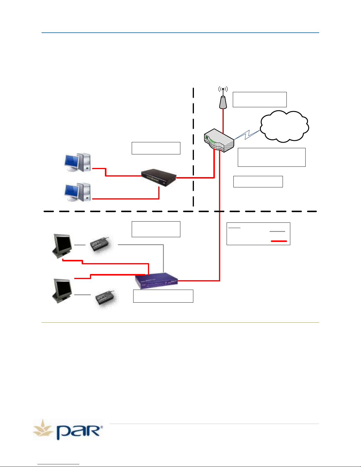
If you are connecting the ES7700 POS System to the Internet via high-speed (broadband) connection,
use the diagram below as a guide. Your ES7700 may also have an optional Zoom Modem which
connects to the phone line. If the high speed internet fails, the zoom modem will act as a back-up.
The diagram on the next page shows a typical configuration for LAN connections.
Figure 22: Typical LAN connection configuration
Page 13
Page 17
PAR POS Installation Manual for TACO DEL MAR
Connect Cash Drawer Cable to POS
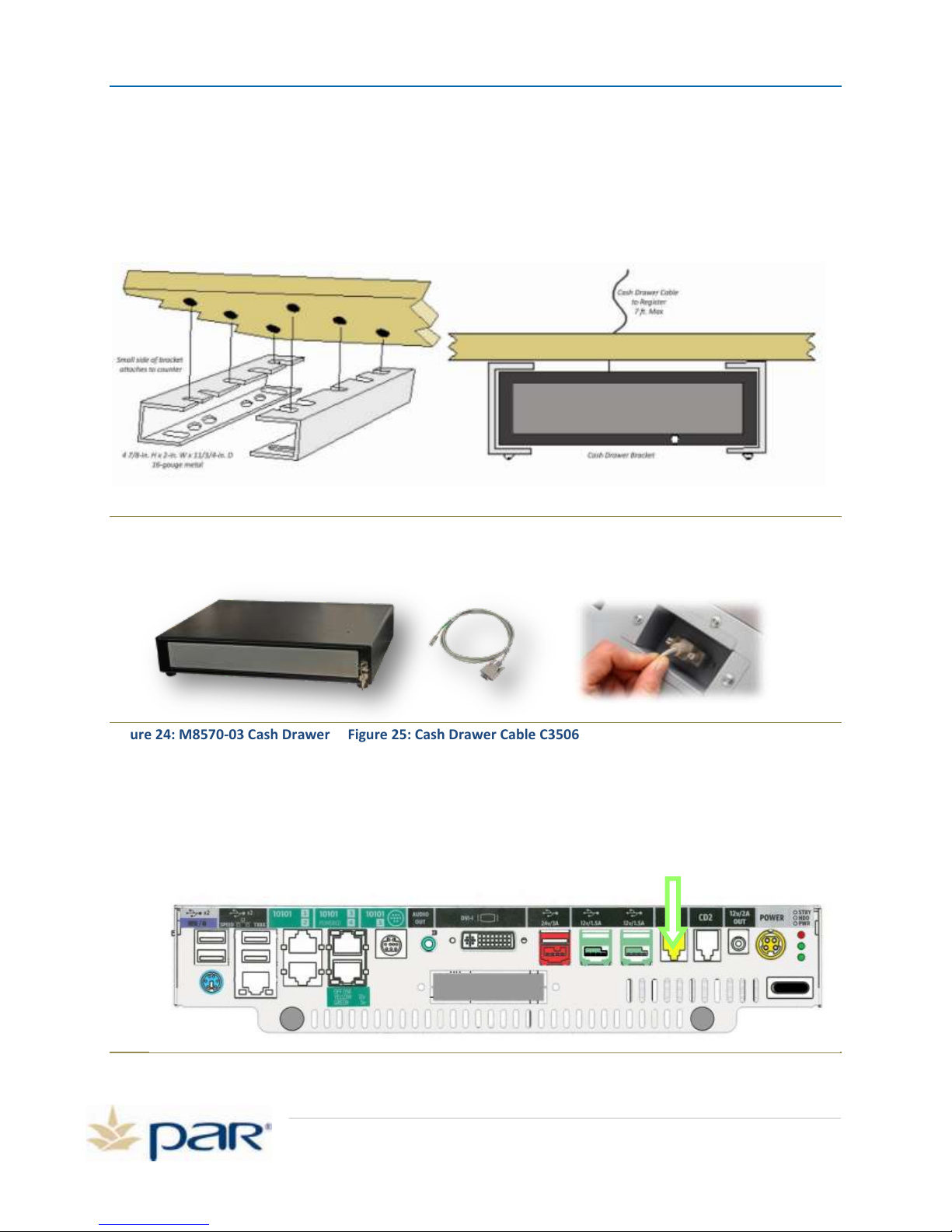
Install K1056 Cas h Drawer Bracket (Optional)
Each cash drawer will be mounted in the K1056 cash drawer brackets. Follow the instructions included
in the cash drawer bracket kit. Before installing, ensure the underside of the counter top is a smooth,
flat surface. If it is not, the cash drawer may experience operational issues.
Figure 23: Install the Cash Drawer Bracket
1. Locate the cable that is packaged with the cash drawer box, part number C3506.
Figure 24: M8570-03 Cash Drawer Figure 25: Cash Drawer Cable C3506 Figure 26: Cash Drawer Cable DB9
2. Turn the cash drawer over and connect the DB9 end of the cash drawer cable to the cash
drawer.
3. Turn the cash drawer upright and install the drawer in its permanent mounting location.
4. Connect the end of the cash drawer cable labeled RJ-11/12 to the cash drawer port labeled
CD1 on the main cable well of the POS terminal. The CD1 port is highlighted in Figure 27.
Page 14
Figure 27: Cash drawer one highlighted
Page 18
PAR POS Installation Manual for TACO DEL MAR
Connect Coin Dispenser to POS (optional)
Note: A software configuration change may be required to make the coin dispener
oper ation al. Call the PAR Help Desk if you need assistance with your coin dispenser
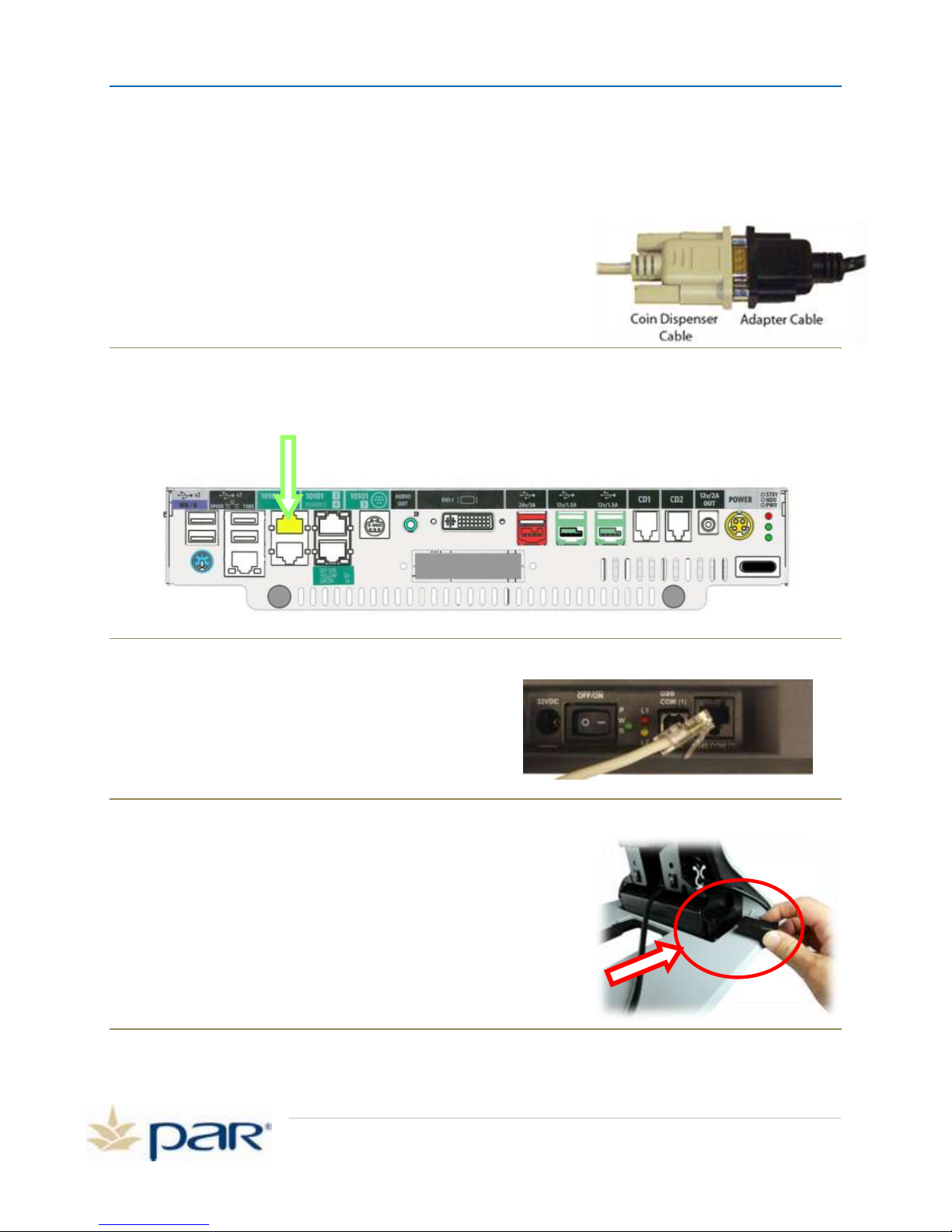
1. Locate the cable that connects your coin dispenser to your POS terminal.
2. Locate the black serial adapter cable, C4823-02.
3. Connect the coin dispenser cable to the adapter cable as
shown here.
Figure 28: Coin Dispenser Cable Connection
4. Connect the RJ-45 end of the adapter cable into the top RJ-45 port (COM port 1) on the POS
terminal. The RJ-45 port is highlighted yellow in the graphic on the next page.
5. Locate the coin dispenser serial cable that you
connected to the POS terminal.
6. Connect this cable to the RJ-45 port on the
coin dispenser as shown below.
Connect POS AC Power Cord to POS Power Supply
1. Route the AC power cord 90 degree connector through the
pedestal and through the white cable retainer located on
the right side of the pedestal above the power supply.
2. Plug the connector into the power supply and make sure
the power supply cable is routed toward the back of the
pedestal frame.
Figure 31: Connect power cord to power supply
Figure 29: RJ-45 port highlighted
Figure 30: Connect cable to Coin Dispenser
Page 15
Page 19
PAR POS Installation Manual for TACO DEL MAR
Install I/O Panel
Cover
Install Pedestal Cover
Install cut out cover
Gather Cables the cables together
and route them through the cable
clamps
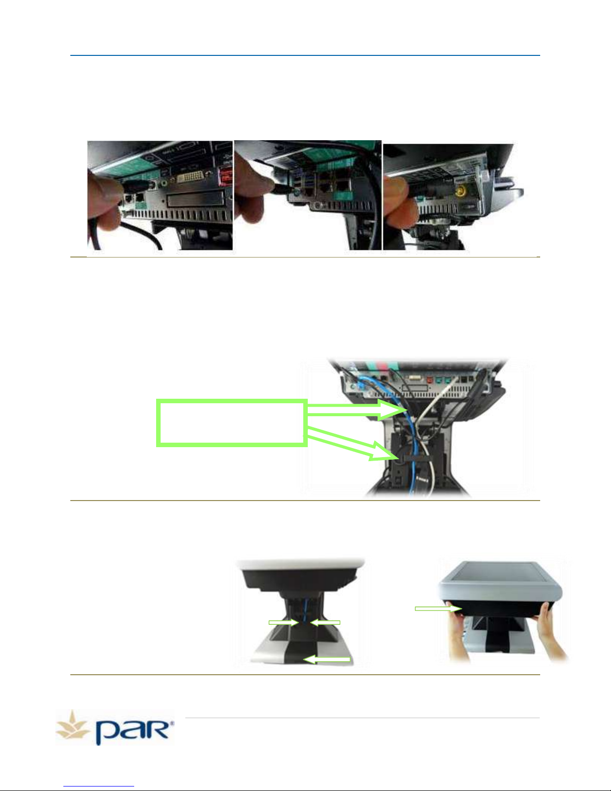
Verify all Cables are Connected to the Terminal
All necessary cables and your power supply have been connected to the POS terminal. Verify that the MSR
card reader, Customer Display and DC power cord are all connected as shown below.
Figure 32: From left: PS2 MSR, Customer Display and Power cable ports
Gather the Cables and Replace Cable Retainers
1. Gather the cables in one hand and replace the cable retainer, securing the cables neatly in place.
Ensure the cables are not kinked or stressed.
2. Stand the POS upright on its base. We will now connect your remaining POS peripherals.
Figure 33: Gather the cables
Install Pedestal Cover and I/O Panel
1. Slide the cover pedestal
cover into position and
tighten the two thumb
screws.
2. Slide the cut out into the
base of the terminal and
snap into place.
3. Slide the I/O panel cover
into position.
Figure 34: Install pedestal and I/O panel cover
Page 16
Page 20
PAR POS Installation Manual for TACO DEL MAR
to wall jack
from modem
Battery Backed Outlet
Power Conditioning
Only Outlet
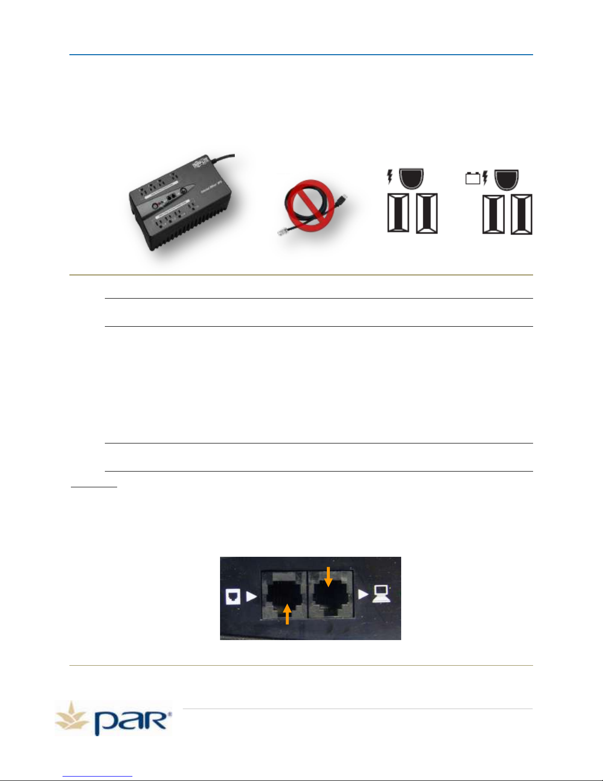
Connect POS Components to UPS
Your POS order includes an Uninterruptible Power Supply, or UPS. This device provides surge protection
for your POS equipment, and battery backup to provide power to your equipment in the event of power
loss. The UPS has 4 battery-backed outlets and 4 surge-protection only outlets.
Figure 35: M3557 UPS – Do not use USB cable that comes with the M3557.
NOTE: This UPS replaces any existing UPS or surge protector that you may have. This ensures
the system is secure in the event of a power interruption.
1. The UPS is located in the shipping box. Remove the UPS from the package marked M3557.
2. Remove and discard the USB cable (Figure 35). The cable is not used at this time.
3. Plug the UPS into an electrical wall outlet.
4. Connect the power cords for the terminal and printer into the battery backed outlets on the
UPS.
5. Press the on/off/test button and hold for 3 seconds until the unit beeps and the light turns
green to turn the UPS on.
NOTE: The M3557 includes a short interface cable that is NOT used in your POS configuration.
You may discard this cable. The cable is shown in Figure 35.
CAUTION: Never plug a laser printer into a UPS. This will overload the UPS and cause it to fail.
1. Connect the POS, and the coin dispenser to the battery-backed outlets.
2. The UPS will also provide surge protection for your modem.
3. If you have a Zoom modem,(optional) connect the telephone cable coming from the Zoom
modem in the telephone jack on the UPS with the computer symbol next to it.
Page 17
Figure 36: Zoom modem (optional) connection
Page 21
PAR POS Installation Manual for TACO DEL MAR
6. Locate the C3901 telephone cable.
7. Connect one end of the C3901 telephone cable telephone jack on the UPS with the wall jack
symbol next to it.
8. Connect the other end of this telephone cable to a telephone wall jack.
Power on the POS Equipment
1. Plug the UPS into a wall outlet.
2. To power on the UPS, press and hold the Power ON button for 1 second until you hear a beep.
3. Ensure that the UPS Battery Backup is powered on.
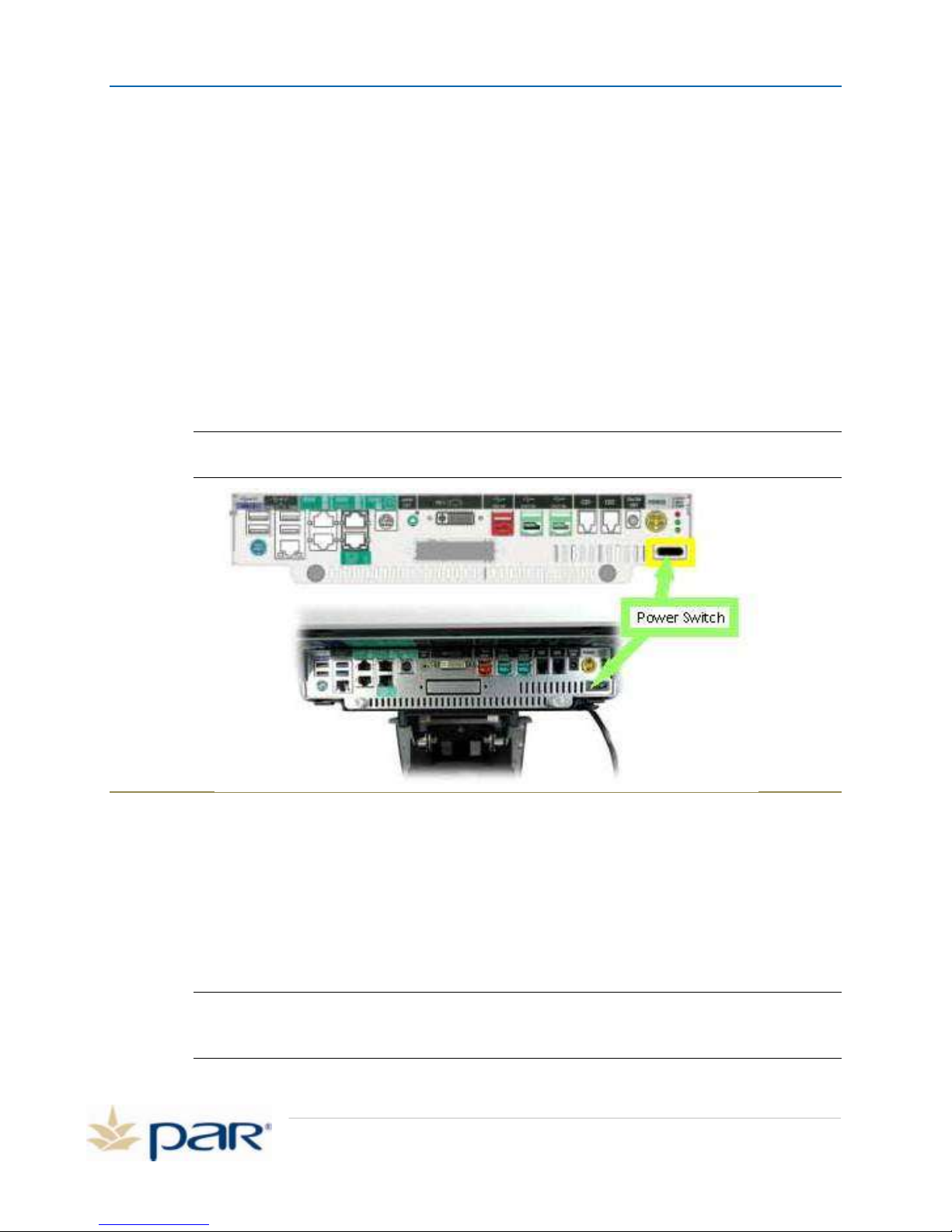
4. Power on the POS terminal. The power button is located on the bottom left side of the top
cover.
5. The power button is black and is highlighted in yellow in the graphic below:
6. Power on your receipt printer and coin dispenser and DVD drive, if present.
NOTE: Your POS system may include hardware components that were not purchased from
PAR. For installation and service of such equipment, contact the equipment vendor
Cleaning the POS Terminal
1. Power down the equipment that you will be cleaning.
2. Dampen a clean towel with carbonated water or glass cleaner. Avoid cleaners that contain
ammonia. Ensure the towel is damp, but not saturated.
3. Wipe down the unit with the damp towel. Never pour or spray cleaner directly in the terminal or
touch screen.
WARNING: Never use abrasive materials to clean the touch screen on a POS terminal. Do
not use sharp objects to clean the edges of the touch screen. A scratch on the surface
could disable the terminal and result in added repair expense.
Cleaning the Magnetic Stripe Reader
Page 18
Figure 37: Power switch location on POS
Page 22
PAR POS Installation Manual for TACO DEL MAR
Contamination builds up on the read/write heads of the magnetic stripe reader (MSR) due to magnetic
oxides, dust, dirt, grease, fingerprint oils, etc. that are on credit cards. The magnetic reader head scrapes
the magnetic stripe on the credit card during the reading process. These contaminants often result in
processing errors, lost data, downtime, and increased magnetic head wear.
MSR Cleaning Kit
If you are experiencing card-read failures, use an MSR cleaning kit to remove the contaminants. The kit
contains a plastic card with nap on both sides and the nap has isopropyl alcohol cleaning solution on it.
The plastic card is passed through the reader like a credit card. The MSR cleaning kit can be ordered from
PAR by ordering part number 803015001.
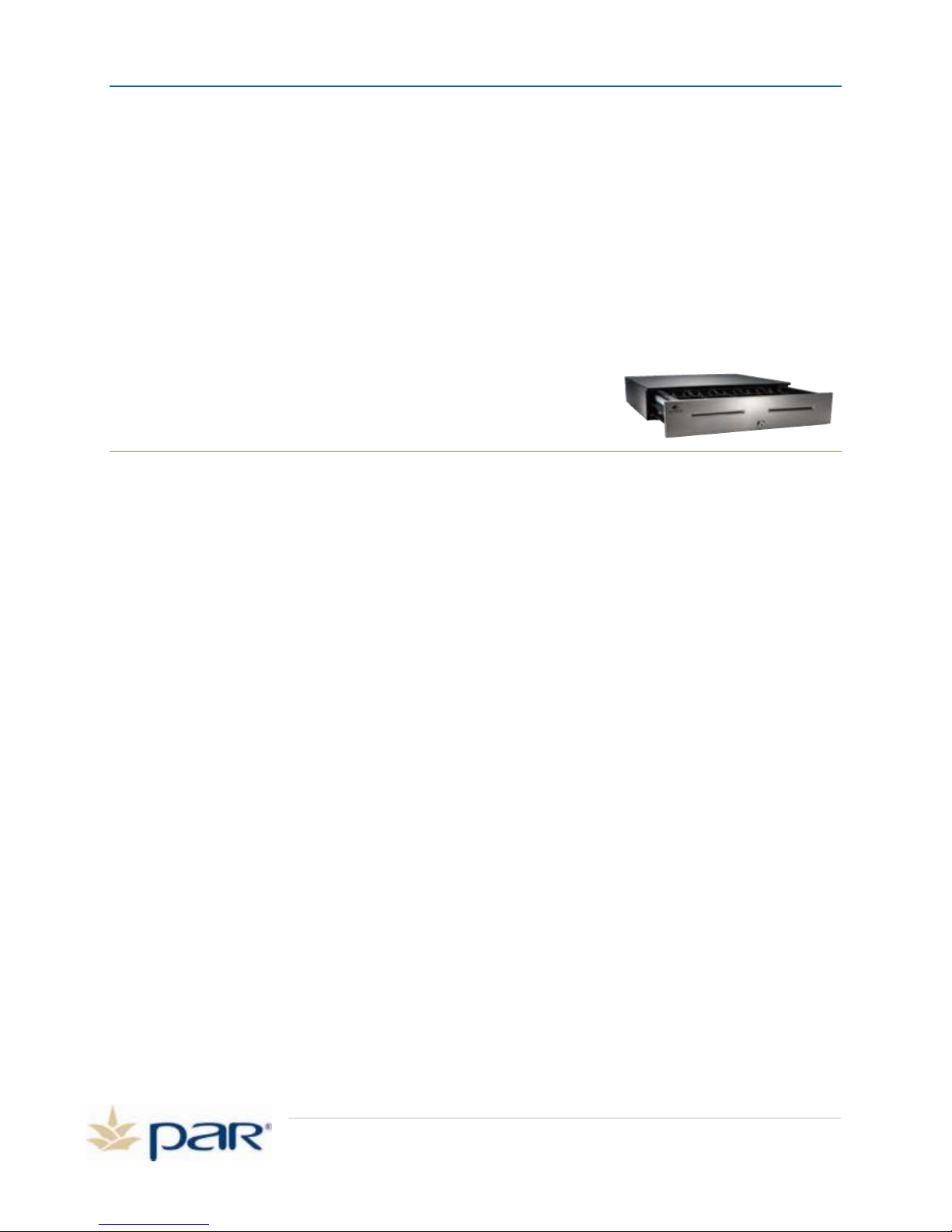
Cleaning the Cash Drawer
The cash drawer should be inspected, cleaned and lubricated
frequently during heavy use. Frequency is dependent on use and the
environment, but the typical recommended frequency is every three
months.
Figure 38: Cash Drawer
1. Open the cash drawer.
2. Using a dry, lint-free cloth, wipe out the old grease and debris from the inner and outer slides.
Do NOT use water or any kind of liquid cleaner.
3. Using a clean applicator, apply a thin layer of lithium-based grease or a few drops of general
purpose oil on the inner and outer slides.
4. Close the cash drawer.
Page 19
Page 23
PAR POS Installation Manual for TACO DEL MAR
Chapter 3:
Pre-Go Live Setup Instructions
In this chapter, you will perform the following steps:
Adding Employees
Customer Receipt Setup
Prices and taxes Setup
Pre-Go Live Instructions
In preparation for going live with your new PAR POS system, complete the following steps:
Step 1: Starting up System
1. Turn on the POS.
2. Select Internet Explorer from Start Menu.
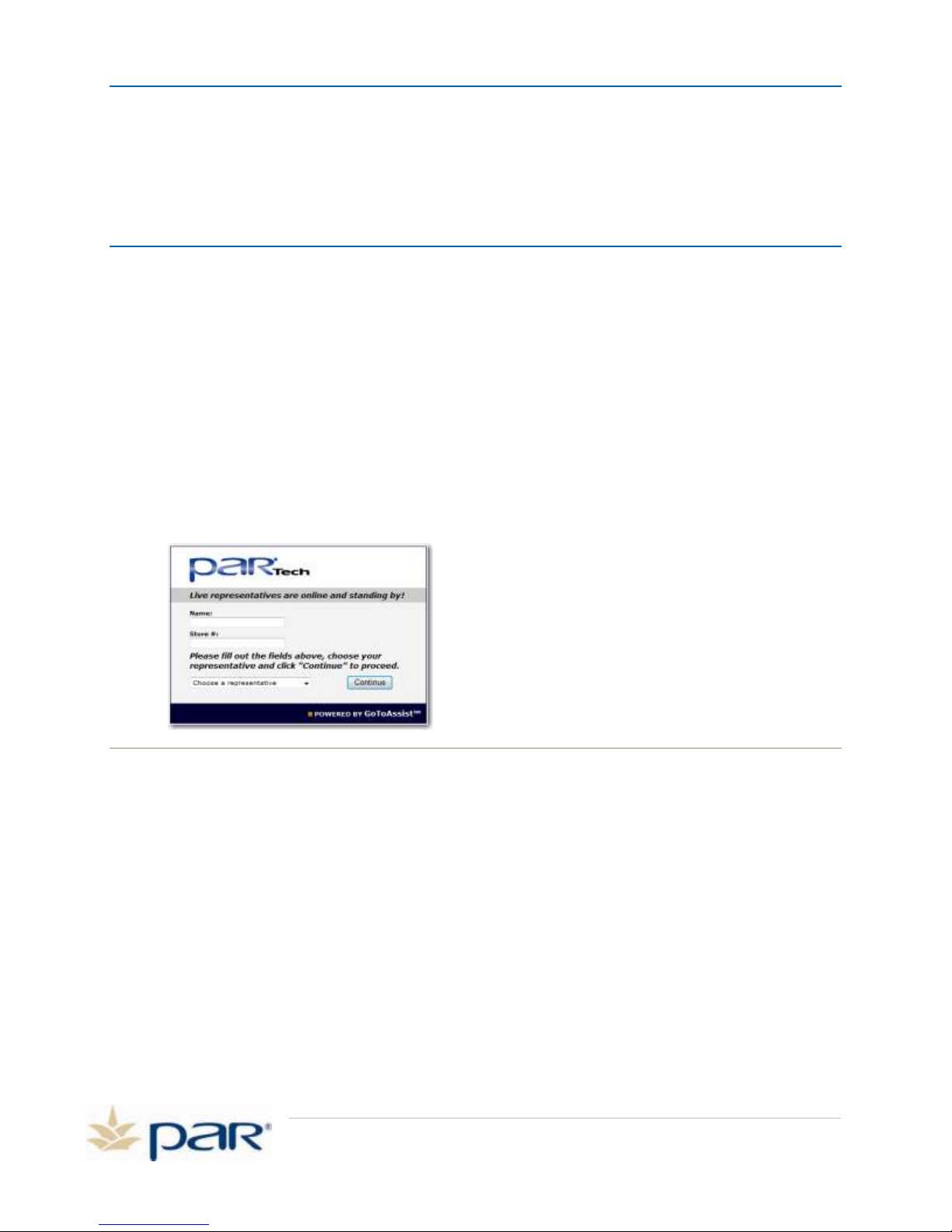
3. You should see the following screen:
Figure 39: PAR GotoAssist Screen
4. If this screen appears then your internet is working on your new PAR system.
5. If this screen does not appear, try another website (google.com, yahoo.com etc.).
6. If websites do not come up, contact your Internet Service Provider for assistance.
7. Exit Internet Explorer page.
8. Wait until the POS loads everything before pressing the Start Day button.
Step 2: Log into Pixel Back Office
1. From the main login screen, click on Manual Login.
2. Enter code 2001 and click OK.
3. Click Yes to clock in.
4. Click System.
5. Select Manager>Back Office: Setup Pixel.
Page 20
Page 24

PAR POS Installation Manual for TACO DEL MAR
Step 3: Verify System Taxes
1. Select Administrator from the pull down menu. Select System Setup.
2. Select Taxes tab.
3. Verify Restaurant tax rates (up to 5 tax rates).
4. Select to save any changes or click Close Form to exit.
Step 4: Verify Company Information
1. Select Administrator from the pull down menu.
2. Select System Setup.
3. Select Company Info tab.
4. Verify information.
5. Make any needed changes.
6. Select to save any changes or click Close Form to exit.
Step 5: Verify System Prices
1. Select Product Setup icon.
2. Click flashlight icon.
3. Verify prices in Price A column.
4. To adjust price, select item and click OK.
5. Make changes to Price A field.
6. Select to save any changes or click Close Form to exit.
Step 6: Add Owner to the System
1. Select Employee Setup icon.
2. Click the flashlight icon.
3. Select the Manager file and click OK.
4. Change the Employee first, last and POS name to owner information.
5. Add additional owner information, as needed. (Address, phone, e-mail, etc.).
6. Click Assign Card.
7. Swipe a new card or click Manual Enter to enter new code and click OK.
8. Click + Add.
9. Verify Franchisee is selected and click OK.
10. For Pay Rate/Hour enter 0 and click OK.
11. Click Advanced tab
12. Verify Quick Order is selected.
13. Select to save any changes.
14. Click + to add another Employee or Close Form to exit.
Page 21
Page 25

PAR POS Installation Manual for TACO DEL MAR
Step 7: Add Employees to the System
1. Select Employee Setup icon.
2. Click + at the bottom of the window.
3. Add new employee information.
4. Click Assign Card.
5. Swipe a new card or click Manual Enter to enter new code and click OK.
6. Click + Add.
7. Select the Job Position and click OK.
8. Enter Pay Rate/Hour and click OK.
9. Click Advanced tab
10. Select Quick Order.
11. Select to save any changes.
Click + at the bottom of the window to add another Employee or Close Form to exit.
Step 8: Verify Receipt Setup
1. Select General Setup from the pull down menu.
2. Click Receipt Setup.
3. Verify the Receipt Header (and Receipt Footer, if applicable) information is correct.
4. Click the Hand with pencil icon to edit.
5. Select to save any changes or click Close Form to exit.
Important notes:
DO NOT use your new PAR POS system to ring actual customer transactions prior to the
completion of your GoLive with a PAR Technician. Credit cards will be staged in “Demo Mode”
for training and will not be active until your system is taken live.
Internet must be working on the PAR POS prior to your GoLive date.
All employees must be entered into the system prior to GoLive.
For menu item changes/additions, please contact the PAR Help Desk at 800-382-6200.
For all other concerns, please contact the PAR Help Desk at 800-382-6200.
Page 22
Page 26
PAR POS Installation Manual for TACO DEL MAR
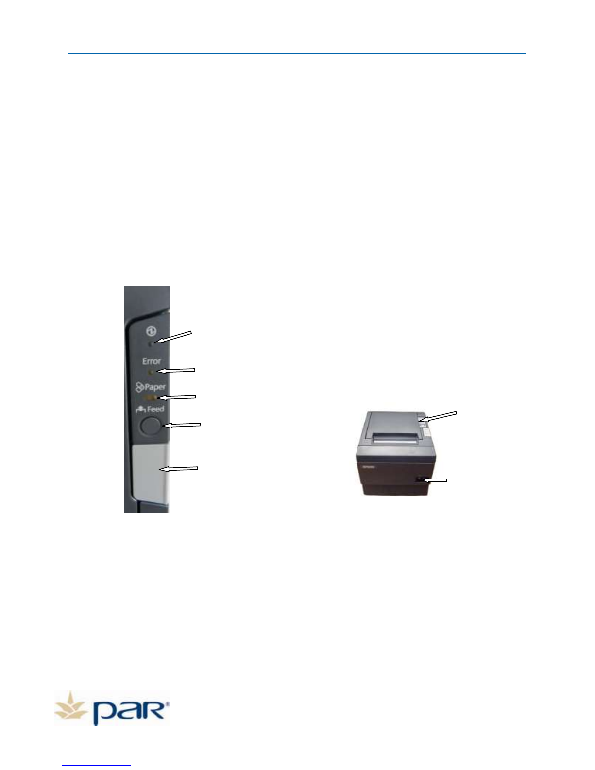
Printer power button
Printer Panel
Power LED
Printer error
LED
Cover open button
Paper feed
button
Paper out LED
Chapter 4:
Troubleshooting
This chapter provides several basic trouble shooting steps.
M3873-61V Printer Troubleshooting Steps
1. Verify the printer is connected, the printer power switch is turned on and the printer green
power LED is on. The printer receives power and print data directly from the register, so the
printer must be connected to the register and the register must be powered on and operational.
Reference Page 10 and 11 for the M3873-61V Printer Installation instructions to make sure the
printer is connected properly.
Figure 40: Epson Printer M3873-61V
2. Verify the printer paper is installed correctly and the Paper-Out LED is off. If not, replace paper,
cycle power, and test for correct printout.
3. Verify the printer Error LED is off. If not, check for a paper jam and clear it, if present. If the
Error LED cannot be cleared, cycle power and test again. If the error does not clear, the printer
may be bad.
4. Verify the printer is printing data and the paper isn’t blank. Make sure the correct thermal paper
is installed.
a. Run a self test on the printer by turning off the printer, pressing and holding the FEED
button while turning on the printer.
Page 23
Page 27

PAR POS Installation Manual for TACO DEL MAR
b. The self-test prints the configuration data that indicates the firmware version interface
configuration, DIP switch settings, etc. A partial printout is shown below:
Firmware Version 30.12 ESC/POS
USB or Serial Interface
Baud rate :9600 bps
Data bits :8 bits
Parity :none
Stop bit :1 bit or more
Handshaking :DTR/DSR
Receive error :prints ‘?’
The printout will end and the paper out indicator will blink, and the paper will cut after
the below is printed out:
Select Modes by pressing Feed button.
Continue SELF-TEST: Less than 1 second
Mode Selection : 1 second or more
c. After the print out pauses, press the FEED button again to continue printing again. Allow
the test to continue until a complete test pattern appears (characters will repeat). The
paper will cut the paper after the below is printed:
!”#$%&’()*+,-./0123456789:;<=>?@ABCDEFGHI
!”#$%&’()*+,-./0123456789:;<=>?@ABCDEFGHIJ
“X$%&’()*+,-./0123456789:;<=>?@ABCDEFGHIJK
#$%&’()*+,-./0123456789:;<=>?@ABCDEFGHIJKL
$%&’()*+,-./0123456789:;<=>?@ABCDEFGHIJKLM
%&’()*+,-./0123456789:;<=>?@ABCDEFGHIJKLMN
*** completed ***
Figure 41: Self Test Pattern
d. Check the printout from the self-test (Figure 41). Make sure that the characters are like
the sample and that a firmware number and date is printed before the character test.
e. Press feed again, turn the power switch to the off position.
5. If the problem still exists, call the Par Help Desk 1-800-382-6200
Cash Drawer Troubleshooting Steps
1. Verify the cash drawer is connected properly. Reference Installation Manual Page 9 for Cash
Drawer Installation.
2. Verify the cash drawer operation manually for smooth operation by using a key to open the
drawer.
a. Using the key manually open and close cash drawer
Page 24
Page 28
PAR POS Installation Manual for TACO DEL MAR
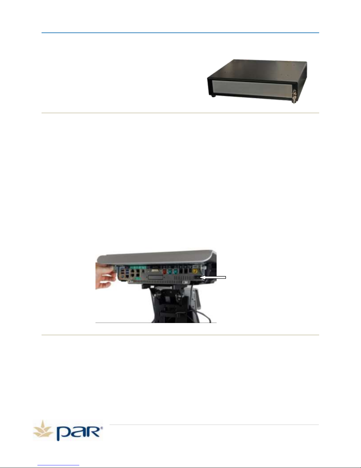
Black power switch
b. Check for smooth operation
c. Clear any obstructions
3. Verify the user is configured for Cash Drawer #1
a. Sign In
b. Go to System
c. Select Your Settings
d. Select Drawer
e. Select #1
f. Press Ok
g. Press Save
h. Exit to Sign In and Try Cash Drawer Again
4. If this doesn’t correct the problem call Par Help Desk 1-800-382-6200
Figure 42: Cash Drawer M8570-03
Register Troubleshooting
1. Press the black power switch located in the left corner under the top cover of the register.
Figure 43: Black power switch
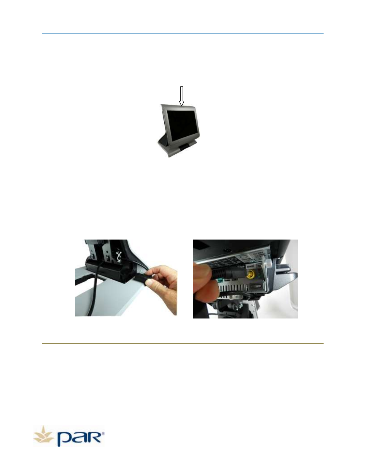
2. Verify the register power LED on.
a. Green – unit is alive and should have display
b. Orange – power management has turned display off. Touch the screen to see if it’s in
power saver mode.
c. No LED lit – Unit is powered down or not connected to AC power.
Page 25
Page 29
PAR POS Installation Manual for TACO DEL MAR
Power LED
Figure 44: ES7700 Power LED
3. Verify the DC power and AC power connectors are plugged into the side of the register.
a. Check the DC power connector on the I/O expansion board located in the pedestal. This
connector is four pin push in connector. Push it straight inward for a positive
connection.
b. Check the AC power cord connection at the power brick.
4. Verify the register AC power cord is connected properly to the M3557 UPS and the UPS is
powered on. Reference Installation Manual Page 17 for M3557 UPS Installation.
5. Verify that the AC Power outlet has power by plugging another device, like a calculator, into the
outlet.
6. If this doesn’t correct the problem call Par Help Desk 1-800-382-6200.
Page 26
Figure 45: AC power cord (left) DC power cord (right), Power Button
Page 30
PAR POS Installation Manual for TACO DEL MAR
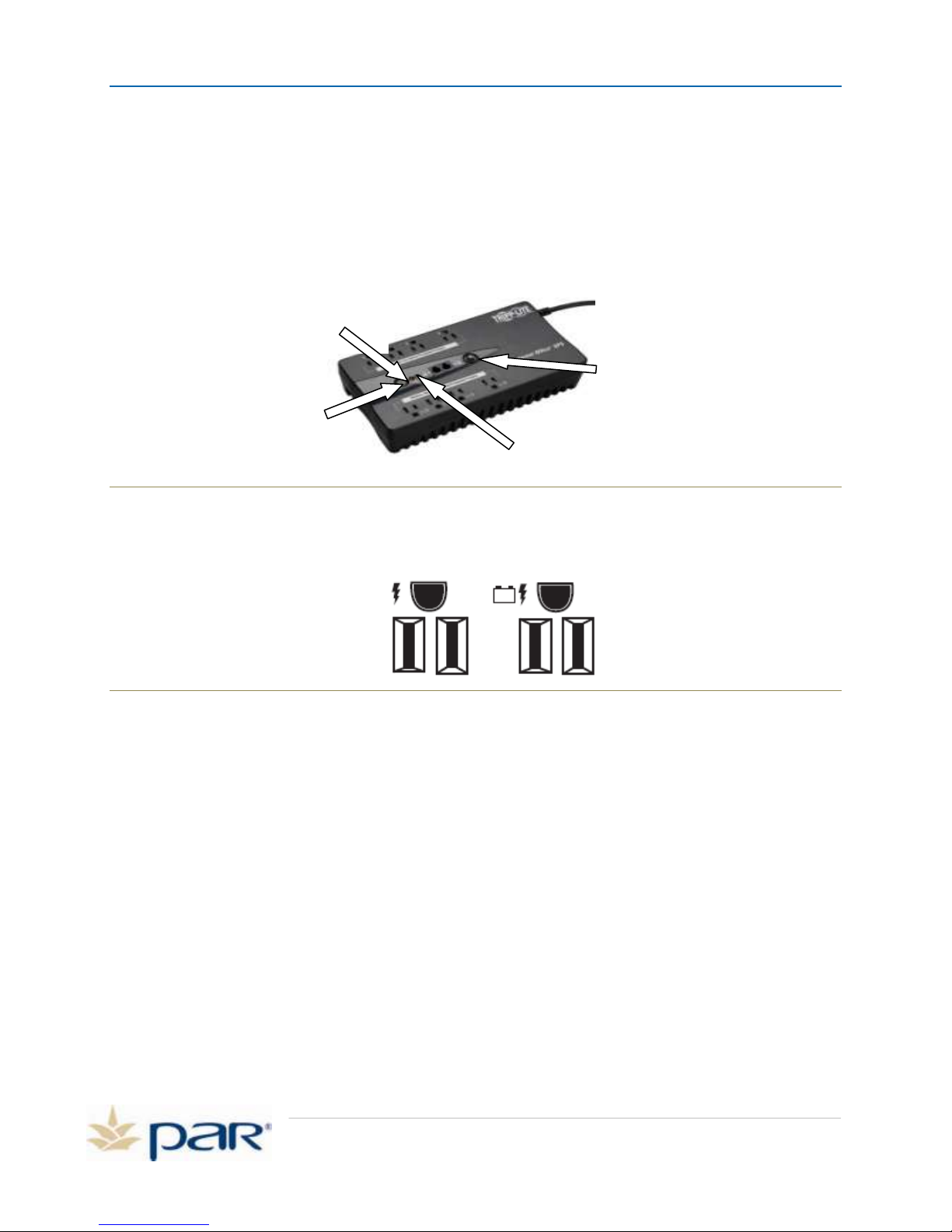
Power button
Red LED: Overload/check
battery
Green: power button
Black: Reset
UPS Troubleshooting
1. Verify the UPS is plugged into a 120 VAC 15 Amp outlet that has AC power, which you can test
by plugging another device into the outlet. Reference Page 17 for the installation instructions to
make sure the UPS is connected properly.
2. Verify that the UPS is powered on, and the green light is on. If not, push the ON/OFF/TEST
button for three seconds until the unit beeps and the light turns green to turn the UPS on.
Figure 46: Tripp Lite UPS
3. Verify the POS equipment is plugged into the UPS power outlets. Figure 47 shows the icons that
indicate the type of outlet.
Figure 47: Surge Only Protected Outlets (left),
Battery-Backup/Surge Protected Outlets (right)
CAUTION: The UPS is designed to support electronic equipment only. The UPS will be overloaded if
the total VA ratings for all the equipment you connect to the Battery Backup/Surge Protected
outlets exceed the UPS’s Output Capacity.
4. Perform a self-test on the UPS:
To Power On: Press and hold the ON/OFF/TEST Button for three seconds. The alarm will beep
once briefly after one second has passed. If utility power is absent, pressing the
Button will “cold-start” the UPS, i.e., turn it on and supply power from its batteries
if fully charged.
To Power Off: Press and hold the ON/OFF/TEST Button for once second. The UPS will be turned
completely off (deactivated).
To run a self test: With the UPS plugged in and turned ON, press and hold the ON/OFF/TEST button for
three seconds.
CAUTION: To perform a self-test, while the unit is powered on, you must hold the ON/OFF/TEST
button continuously for three seconds; if you release the button too early, you will turn the UPS
Page 27
Page 31

PAR POS Installation Manual for TACO DEL MAR
system OFF and cut power to connected equipment loads. To ensure you hold the button for the
correct length of time, do not release the button until you hear the UPS System’s audible alarm
beep twice. The first beep occurs after one second and indicates that the UPS will turn OFF if the
button is released. The second beep occurs after three seconds and indicates that the UPS will
perform a self-test if the button is released.
The test will last approximately 10 seconds as the UPS switches to battery to test its load capacity
and charge. All LEDs will be lit and the UPS alarm will sound. See LED descriptions below to
determine the results of the Self-Test.
ON/OFF LED:
This green LED lights continuously to indicate that the UPS is ON and supplying your equipment with
AC power either from a utility source or from the UPSs internal batteries. If the UPSs alarm is
sounding (4 short beeps followed by a pause), the UPS is operating from its internal batteries.
Overload/Check Battery LED:
This red LED lights continuously after a self-test to indicate the capacity of the battery-supported
outlets has been exceeded. To clear the overload, unplug some of your equipment from the batterysupported outlets; then use the ON/OFF/TEST button to run a Self-Test. If the UPS continues to
detect an overload, remove more equipment and repeat the self-test until successful.
CAUTION! Any overload that is not corrected by the user immediately following a self-test may
cause the UPS to shut down and cease supplying output power in the event of a blackout or
brownout. The LED flashes to indicate the battery needs to be recharged or replaced. If the LED
flashes (and a continuous alarm sounds) during a prolonged blackout or brownout, the UPS’s
batteries are nearly out of power; you should save files and shut down your equipment
immediately. If the LED flashes following a UPS self-test (after the UPS is turned ON), it may indicate
that the battery needs to be replaced. Allow the UPS to recharge continuously for 12 hours, then
use the ON/OFF/TEST button to run a self-test. If the LED continues to flash, the unit needs to be
replaced.
Page 28
Page 32

PAR Phone Numbers
For Service
USA and CANADA: 800.382.6200
For Parts
USA and CANADA: 800.PAR.PART
For Sales
Continental USA except New York: 800.448.6505
Outside Continental USA: 315.738.0600
 Loading...