

Page 1

INSTRUCTION MANUAL
740 Monitor
Portable Suspended Solids
Page 2

**This page is left blank**
Page 3

740 Portable Suspended Solids
Table of Contents
1 Introduction................................................................................................................... 7
1.1 General ............................................................................................................ 7
1.2 Display ............................................................................................................. 7
1.3 Key Pad ...........................................................................................................7
1.4 Sensors ............................................................................................................7
1.5 Manual Conventions ........................................................................................7
2 Basic Operation............................................................................................................ 9
2.1 Switching On and Off ....................................................................................... 9
2.2 Measure Mode ................................................................................................. 9
2.3 Measurement Cycle .........................................................................................9
2.4 Display ............................................................................................................. 9
2.5 Profiles ........................................................................................................... 10
3 Configuration...............................................................................................................11
3.1 Menu Mode .................................................................................................... 11
3.2 Data Entry ...................................................................................................... 11
3.2.1 User List Selection ....................................................................................11
3.2.2 User Value Entry ...................................................................................... 12
3.2.3 User Text Entry .........................................................................................13
4 User Profiles............................................................................................................... 14
4.1 Presets ...........................................................................................................14
4.2 Example Profile Configuration .......................................................................14
5 Select Profile...............................................................................................................16
6 New Profile Wizard..................................................................................................... 17
6.1 New Profile Wizard Keys ...............................................................................17
6.2 New Profile Wizard Stages.............................................................................17
7 Profile Config.............................................................................................................. 19
172430IM-Iss07.odt 172430IM-Iss07 Issue Date 23/10/2014 Page 3 of 46
Page 4

740 Portable Suspended Solids
7.1 Profile Name ..................................................................................................19
7.2 Profile User ....................................................................................................19
7.3 Profile Date ....................................................................................................19
7.4 Measurement Title .........................................................................................20
7.4.1User Defined Title ......................................................................................20
7.5 Display Units .................................................................................................. 20
7.5.1User Defined Units .................................................................................... 20
7.5.2 Linked Units ..............................................................................................21
7.6 Set Damping Range ......................................................................................21
8 Profile Advanced Config............................................................................................. 22
8.1 Lookup Table Mode .......................................................................................22
8.2 Adjust X Values .............................................................................................22
8.3 Adjust Y Values .............................................................................................22
8.4 Constant A, B, C ............................................................................................22
9 Monitor Config.............................................................................................................23
9.1 Bleeper ..........................................................................................................23
9.2 Backlight ........................................................................................................23
9.3 Auto Shutdown ..............................................................................................23
9.4 Language ....................................................................................................... 23
9.5 Change Password .........................................................................................23
9.6 Monitor Adv Config.........................................................................................24
9.6.1 Factory Cal Values (1 to 5) .......................................................................24
9.7 Load Monitor Defaults .................................................................................... 24
10 Profile Calibration......................................................................................................25
10.1 Calibration – General ...................................................................................25
10.2 Methods of Calibration .................................................................................25
10.2.1Primary Standard .....................................................................................25
10.2.2 Secondary Standard ...............................................................................25
10.2.3 Calibration Intervals ................................................................................26
Page 4 of 46 172430IM-Iss07 Issue Date 23/10/2014
Page 5

740 Portable Suspended Solids
10.3 Preparing for Calibration ..............................................................................26
10.4 Calibration Wizard .......................................................................................26
10.4.1 Cal Wizard Keys .....................................................................................27
10.4.2 Cal Wizard Stages ..................................................................................27
10.5 Set Zero .......................................................................................................27
10.6 Set Span ......................................................................................................28
10.6.1 Step 1. Calibration Value Entry ..............................................................28
10.6.2 Step 2. Calibrating ..................................................................................28
10.7 Take Sample ................................................................................................29
10.8 Enter Sample Result ....................................................................................30
11 Information................................................................................................................31
11.1 Profile Information ........................................................................................ 31
11.2 Software Version .........................................................................................31
11.3 Contact Information .....................................................................................31
11.4 Battery Status ..............................................................................................31
11.5 Sensor Input ................................................................................................31
12 Instrument Security...................................................................................................32
12.1 Lock Instrument ...........................................................................................32
12.2 Change Password .......................................................................................32
13 Error Messages.........................................................................................................33
13.1 Measurement ............................................................................................... 33
13.1.1 Display Over Range ............................................................................... 33
13.1.2 Display Under Range .............................................................................33
13.2 Sensor .........................................................................................................33
13.2.1No Sensor ................................................................................................33
13.2.2Sensor Low Limit .....................................................................................33
13.2.3Sensor High Limit ....................................................................................33
13.2.4Not Available - Sensor Fault ....................................................................33
13.2.5Sensor Input Too High (Set Zero) ...........................................................33
172430IM-Iss07.odt 172430IM-Iss07 Issue Date 23/10/2014 Page 5 of 46
Page 6

740 Portable Suspended Solids
13.2.6Sensor Input Too Low (Set Zero).............................................................33
13.2.7Sensor Input Too Low (Set Span) ...........................................................33
14 Battery Charging....................................................................................................... 35
14.1 Battery .........................................................................................................35
14.2 Charger ........................................................................................................ 35
15 Maintenance............................................................................................................. 36
15.1 Sensor Replacement ...................................................................................36
16 Presets Measurements............................................................................................. 37
17 User Profile setup Record.........................................................................................38
18 Technical Support..................................................................................................... 39
18.1 Returning Equipment for Repair ..................................................................39
19 Technical Specification (should be last section).......................................................40
19.1 Electrical Information ...................................................................................40
19.2 Physical Features ........................................................................................40
19.3 Software Features .......................................................................................40
20 Preparation of Fullers Earth......................................................................................41
21 Preparation of Formazin Turbidity Standard.............................................................42
21.1 Health & Safety Precautions ........................................................................42
21.2 Method of Preparation .................................................................................42
21.3 Preparation of Dilution's ...............................................................................42
21.4 Calibration .................................................................................................... 43
21.5 Storage Life .................................................................................................43
22 Declaration of CE Conformity...................................................................................44
Page 6 of 46 172430IM-Iss07 Issue Date 23/10/2014
Page 7

740 Portable Suspended Solids
1 Introduction
1.1 General
The 740 Monitor is used for processing and displaying the output signal from a Partech
sensor. It combines a clear display of the measured parameter, a simple user interface,
with good flexibility to enable configuration to satisfy the users needs.
1.2 Display
The 740 display indicates the measured value with large numerals for good visibility
with an additional status line that shows the current settings, battery status and any
faults that are present. The display has a backlight to enable use of the monitor in low
light conditions and also has automatic contrast settings.
The measurement title, units and display range can all be user set to suit the sensor
being used and the application being monitored.
1.3 Key Pad
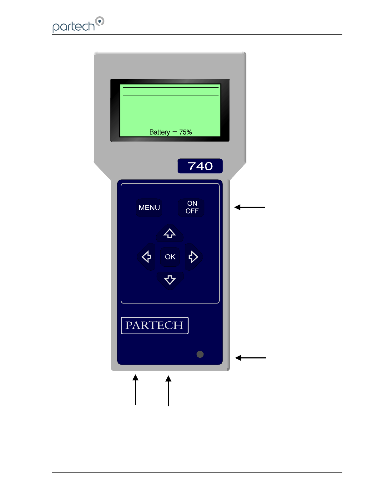
A six key tactile membrane keypad is used for all configuration and operation of the
740 Monitor; each key has a very positive operation enabling use even whilst wearing
gloves.
1.4 Sensors
The 740 Monitor can be used with the Partech Soli-Tech 10 (ST10).
1.5 Manual Conventions
This instruction manual describes the configuration and operation of the 740 Monitor
and where required includes some information regarding sensors. It is therefore very
important that it is used in conjunction with the relevant sensor instruction manual. All
dimensions stated in this manual are in millimetres unless otherwise stated.
The manual has been written on the basis that the user has a basic knowledge of
instrumentation and an understanding of the type of measurement being made.
Training in the use of the 740 Monitor can be provided by Partech, please contact
Partech for further information
172430IM-Iss07.odt 172430IM-Iss07 Issue Date 23/10/2014 Page 7 of 46
Page 8
740 Portable Suspended Solids
Page 8 of 46 172430IM-Iss07 Issue Date 23/10/2014
Figure 1 740 Monitor
CHARGE
S U S P E N D E D S O L I D S
m g / l
1 5 0 0
Charger
Socket
ON/OFF Key
Charge LED
Sensor
Connection
Page 9
740 Portable Suspended Solids
2 Basic Operation
2.1 Switching On and Off
The 740 Monitor can be turned on and off using the ON/OFF key. When the monitor is
turned on it displays a start-up screen prior to entering Measure Mode. The instrument
can be switched off at any time by pressing the ON/OFF key.
2.2 Measure Mode
The normal operating mode for the 740 Monitor is measure mode and this is active
when the measured value is displayed in large numbers. Whilst in measure mode the
display value is continually updated based upon the current sensor input signal.
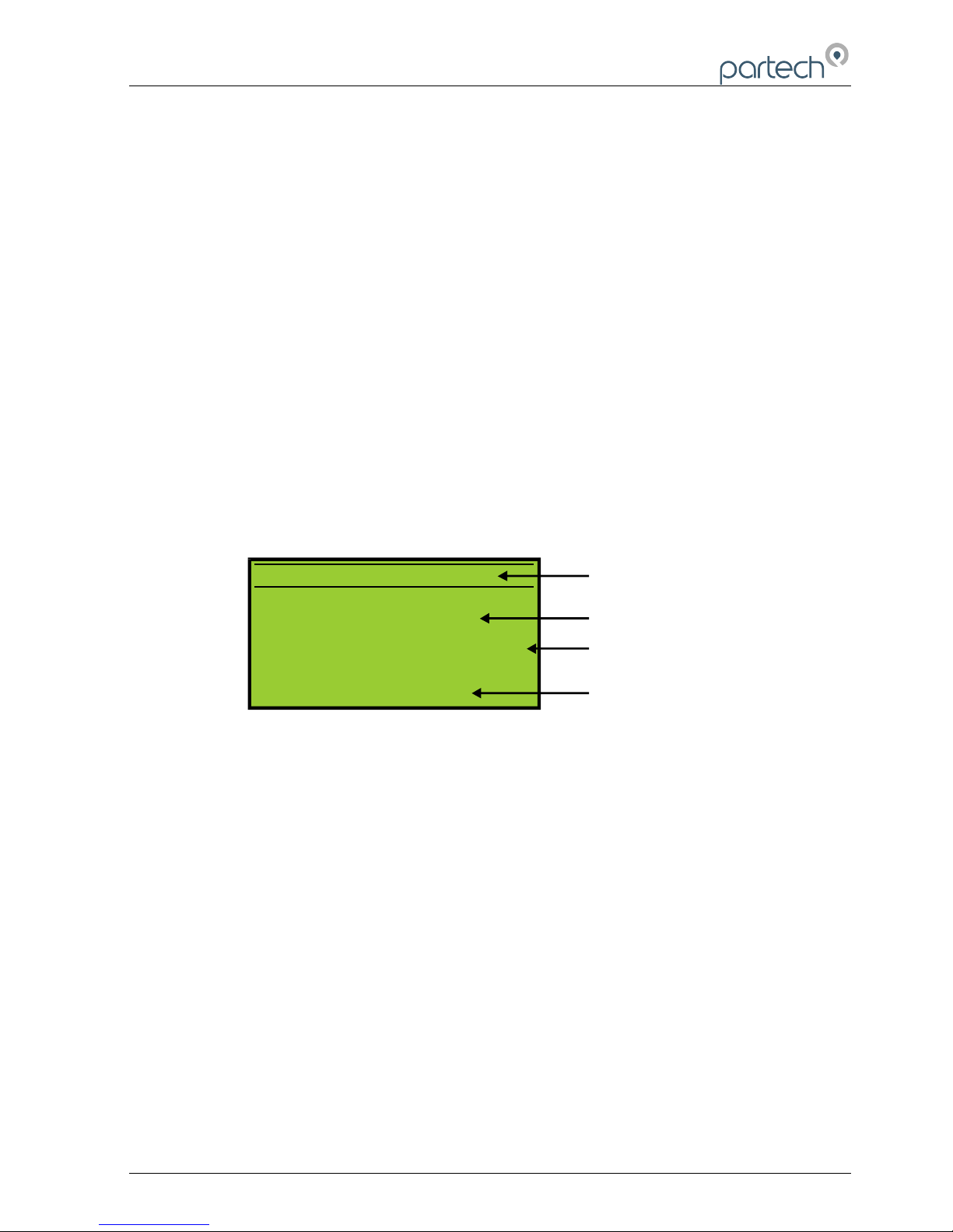
The display in measure mode also includes a status bar that scrolls through the status
of the battery, details of the instrument settings and if the instrument is locked. The
status bar is also used to indicate any instrument faults that are present.
S U S P E N D E D S O L I D S
B a t t e r y = 7 5 %
m g / l
1 5 0 0
Status Text
Measurement Title
Display Value
Units
2.3 Measurement Cycle
The measurement cycle is carried out in the background at all times when the
instrument is switched on regardless of whether the instrument is in measure mode or
not. The monitor performs five measurement cycles per second enabling a response
time of one fifth of a second (with damping rate set to Instant – see damping).
2.4 Display
The resolution of the displayed value is determined by the sensor range setting, such
that only sensible display values are indicated; the same range also determines the
calibration value range.
The display units and measurement title are user selectable and should be chosen to
suit the parameter being monitored and sensor being used.
172430IM-Iss07.odt 172430IM-Iss07 Issue Date 23/10/2014 Page 9 of 46
Figure 2 Measure Mode Display
Page 10

740 Portable Suspended Solids
2.5 Profiles
The 740 Monitor allows the user to define up to 10 Profiles, each profile will be based
on a preset configuration which can be modified to suit the actual measurement
required.
Page 10 of 46 172430IM-Iss07 Issue Date 23/10/2014
Page 11
740 Portable Suspended Solids
3 Configuration
3.1 Menu Mode
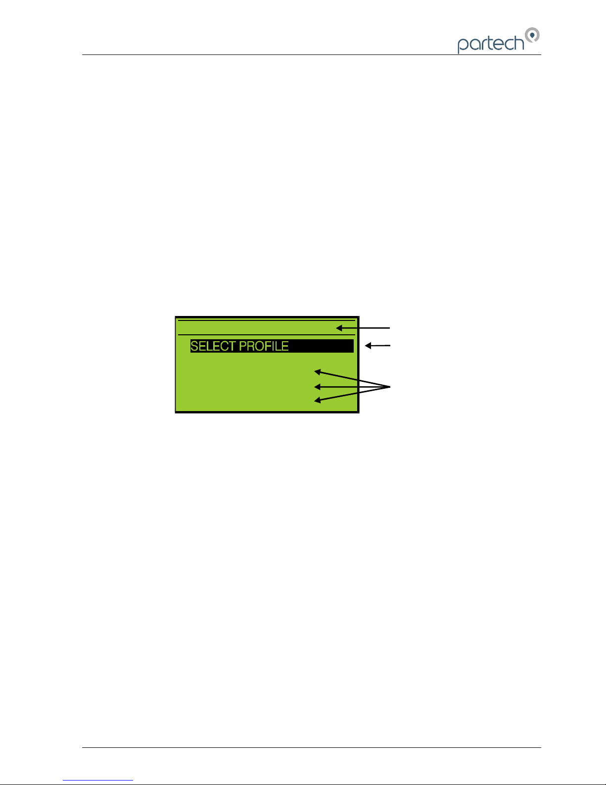
To access the main menu, press the MENU key when the instrument is in measure
mode. Pressing the MENU key when the main menu is displayed will return the
instrument to the measure mode. When the main menu is displayed, the keys can
be used to move the selection bar. Pressing the OK key will activate the selected item.
If the instrument is left in any display other than measure mode, it will automatically
return to measure mode after one minute has passed with no key presses. When a sub
menu is displayed, pressing the MENU key will exit the current menu and return to the
previous menu. If a menu consists of more than six items, UP and DOWN arrows will
appear to indicate if there are menu items above or below those displayed.
3.2 Data Entry
To provide the user with a simple interface, the 740 uses three methods of data entry
for the setting of all the user configurable parameters. The various methods of user
data entry used on the 740 are described below:
3.2.1 User List Selection
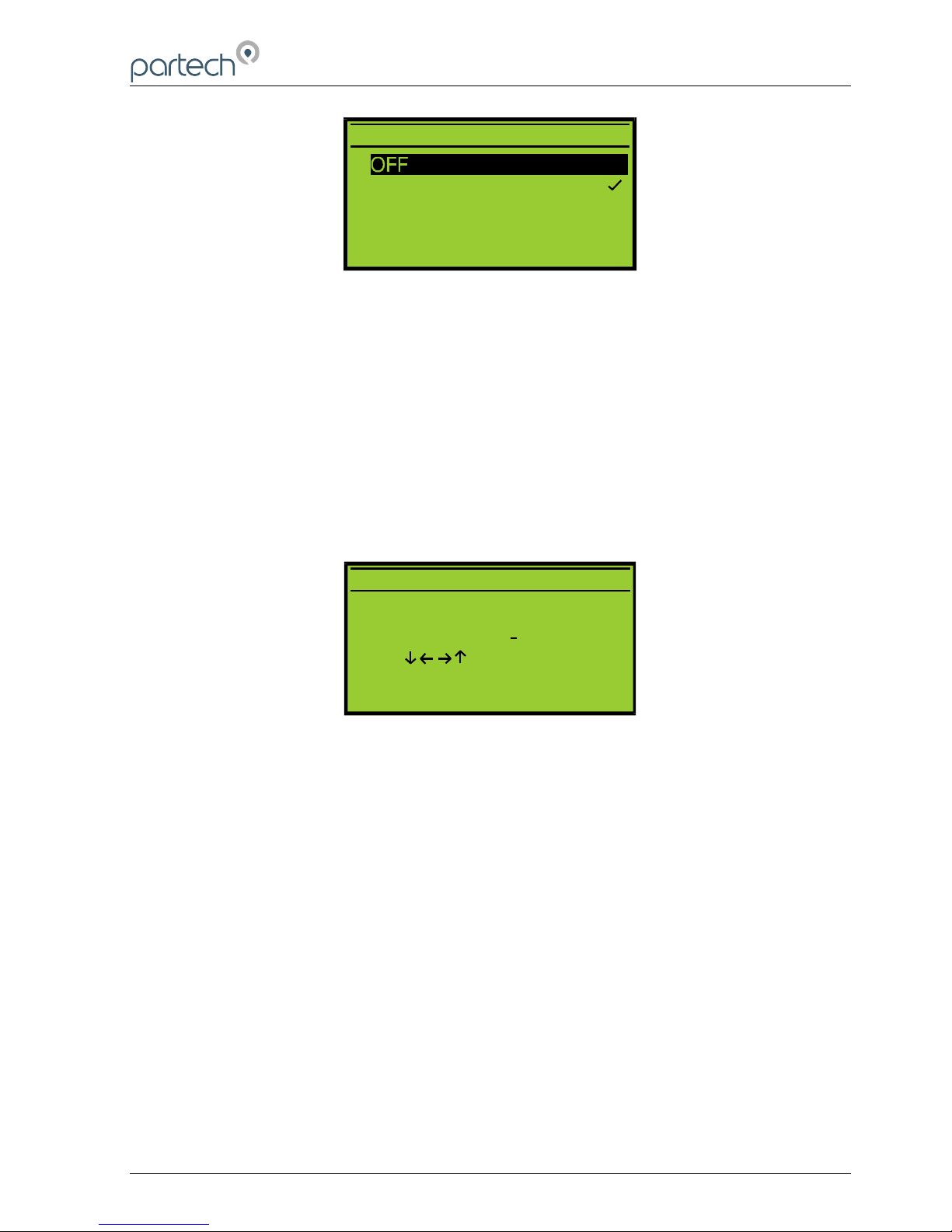
This method of user data entry is used when a selection from a predefined list of option
is required such as sensor type, display range and backlight mode. The list of possible
selections will be displayed and a small tick will identify the current setting. If the list
contains more than five items, small UP and DOWN arrows will appear on the display
to indicate there are more items than that displayed. To make a selection, the selector
bar can be moved using the keys, to select the required item. Pressing the OK key
will select the highlighted item and a small tick will appear next to it. Pressing the
MENU key will exit the list selection menu.
172430IM-Iss07.odt 172430IM-Iss07 Issue Date 23/10/2014 Page 11 of 46
M A I N M E N U
P R O F I L E C O N F I G
M O N I T O R C O N F I G
I N F O R M A T I O N
L O C K I N S T R U M E N T
Menu Title
Menu Items
Selector Bar
Figure 3 Menu Display
Page 12
740 Portable Suspended Solids
3.2.2 User Value Entry
When a numerical value is to be set, the current value will be displayed with a flashing
cursor. The range of adjustment of the value is predefined and therefore only values
within this range can be entered. To adjust a value, the keys are used to select a
digit and the keys are used to increment/decrement the digit. When the new value
has been set pressing the OK key will store it and exit from the value adjustment
display. To exit without saving changes press the MENU key.
Page 12 of 46 172430IM-Iss07 Issue Date 23/10/2014
B L E E P E R
O N
E N T E R U S E R P A S S W O R D
0 0 0 0
U s e t o s e t v a l u e
P r e s s O K t o a c c e p t
P r e s s M E N U t o c a n c e l
Figure 4 List selection Display – note tick indicating current value
Figure 5 Value Entry Display
Page 13
740 Portable Suspended Solids
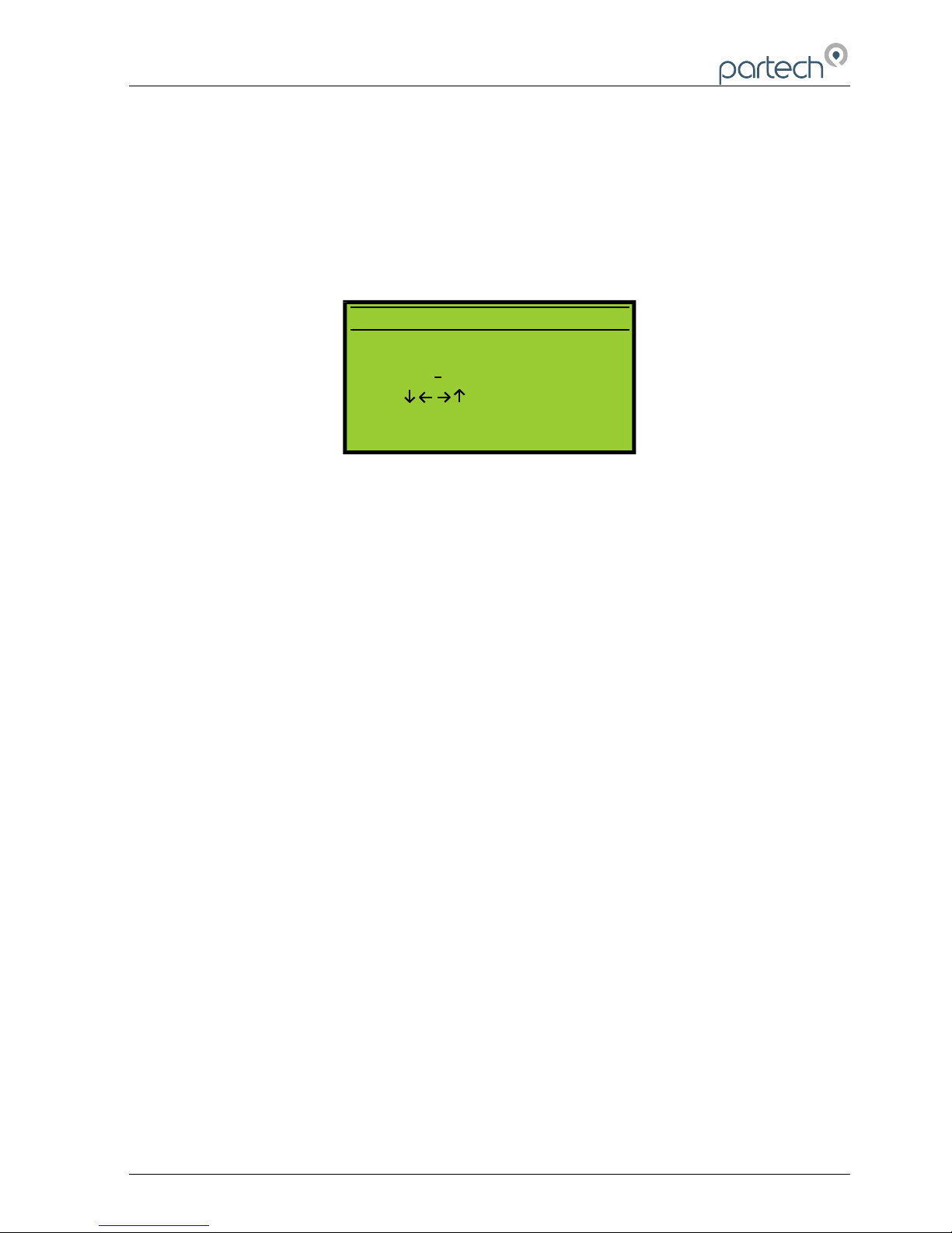
3.2.3 User Text Entry
Using this method of data entry, the user is able to enter or edit text and is used for the
user defined measurement title and units. The text string is displayed with a flashing
cursor indicating the selected character. The keys are used to select a character,
and the keys to change the selected character. When all changes are complete
press the OK key to store the text string. To exit without saving changes press the
MENU key.
172430IM-Iss07.odt 172430IM-Iss07 Issue Date 23/10/2014 Page 13 of 46
E D I T U S E R T I T L E
A e r a t i o n L a n e 1
U s e t o s e t v a l u e
P r e s s O K t o a c c e p t
P r e s s M E N U t o c a n c e l
Figure 6 Text Entry Display
Page 14
740 Portable Suspended Solids
4 User Profiles
Understanding the concept of profiles is key to the successful operation of the 740
Monitor. A profile is used to store the configuration and calibration data for a particular
measurement. The 740 Monitor is capable of storing up to ten profiles, the actual
number required will depend upon the number of different measurements to be made.
Normally a separate profile is required for each different measurement to be made, for
example final effluent suspended solids and mixed liquor suspended solids.
4.1 Presets
To reduce the setup time of the 740 Monitor, several preset measurements are
available that the user can choose from when creating a new profile. Each of these
presets contains configuration and calibration data for commonly made measurements.
Note: The presets provide a fast route to completing the instrument setup.
However as they use calibration data established from reference measurements,
it may be necessary to carry out calibration to improve upon the measurement
accuracy.
4.2 Example Profile Configuration
Mr Bill Smith has a 740 Monitor which he uses at Charlestown Waste Water Treatment
Works to measure the mixed liquor suspended solids and the final effluent.
The monitor has been set up with two profiles (the remaining profiles are unused) as
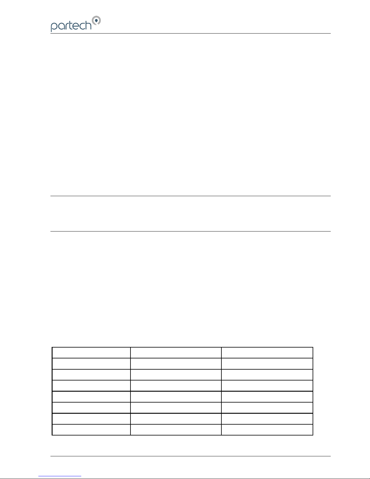
shown below:
Profile 1 - Mixed Liquor Suspended Solids
Parameter Value Comment
Profile Name Charlestown MLSS
Profile User Bill Smith
Profile Date 25/12/2001 Date profile created
Measurement Title Suspended Solids
Display Units mg/l
Display Range 0 - 20000 Typical value 3500mg/l
Damping Rate Medium
Page 14 of 46 172430IM-Iss07 Issue Date 23/10/2014
Page 15
740 Portable Suspended Solids
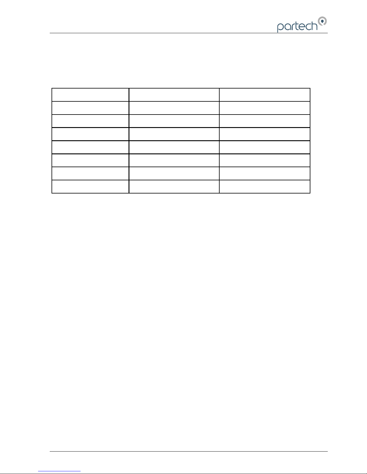
Profile 2 - Final Effluent Suspended Solids
Parameter Value Comment
Profile Name Charlestown F.E. Can't fit "Final Effluent"
Profile User Bill Smith
Profile Date 25/12/2001 Date profile created
Measurement Title Suspended Solids
Display Units mg/l
Display Range 0 - 200 Typical value 25mg/l
Damping Rate Medium
172430IM-Iss07.odt 172430IM-Iss07 Issue Date 23/10/2014 Page 15 of 46
Page 16
740 Portable Suspended Solids
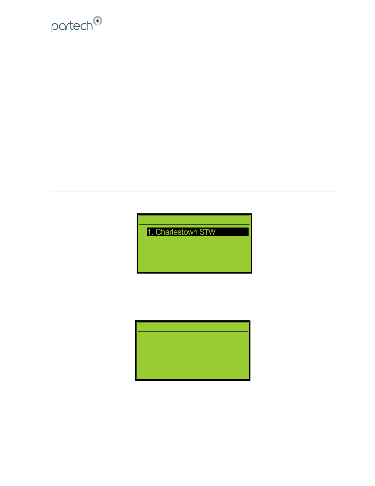
5 Select Profile
To choose which profile to use, the Select Profile option is selected on the main menu.
The ten profiles are listed, if a profile has been setup the profile name is displayed
otherwise the profile is indicated as empty.
The active profile is indicated with a tick. To select another profile use the keys to
move the highlight bar then press the OK key. Information about the profile will be
displayed with a prompt to use the selected profile.
Note: If a profile name was entered at the time the profile was setup this will be
shown, if a name was not entered the default name will be displayed e.g. Profile
One. Only the first fifteen characters of a user entered profile name are
displayed.
Page 16 of 46 172430IM-Iss07 Issue Date 23/10/2014
M A I N M E N U
2 . S t A u s t e l l S T W
3 . < E m p t y >
4 . < E m p t y >
5 . < E m p t y >
M A I N M E N U
2 . S t A u s t e l l S T W
3 . < E m p t y >
4 . < E m p t y >
5 . < E m p t y >
S E L E C T P R O F I L E
C h a r l e s t o w n S T W M L S S
B i l l S m i t h
2 2 / 0 8 / 2 0 0 1
P r e s s O K t o a c c e p t
P r e s s M E N U t o c a n c e l
Figure 7 Select Profile
Figure 8 Selected Profile Information & Confirmation
Page 17
740 Portable Suspended Solids
6 New Profile Wizard
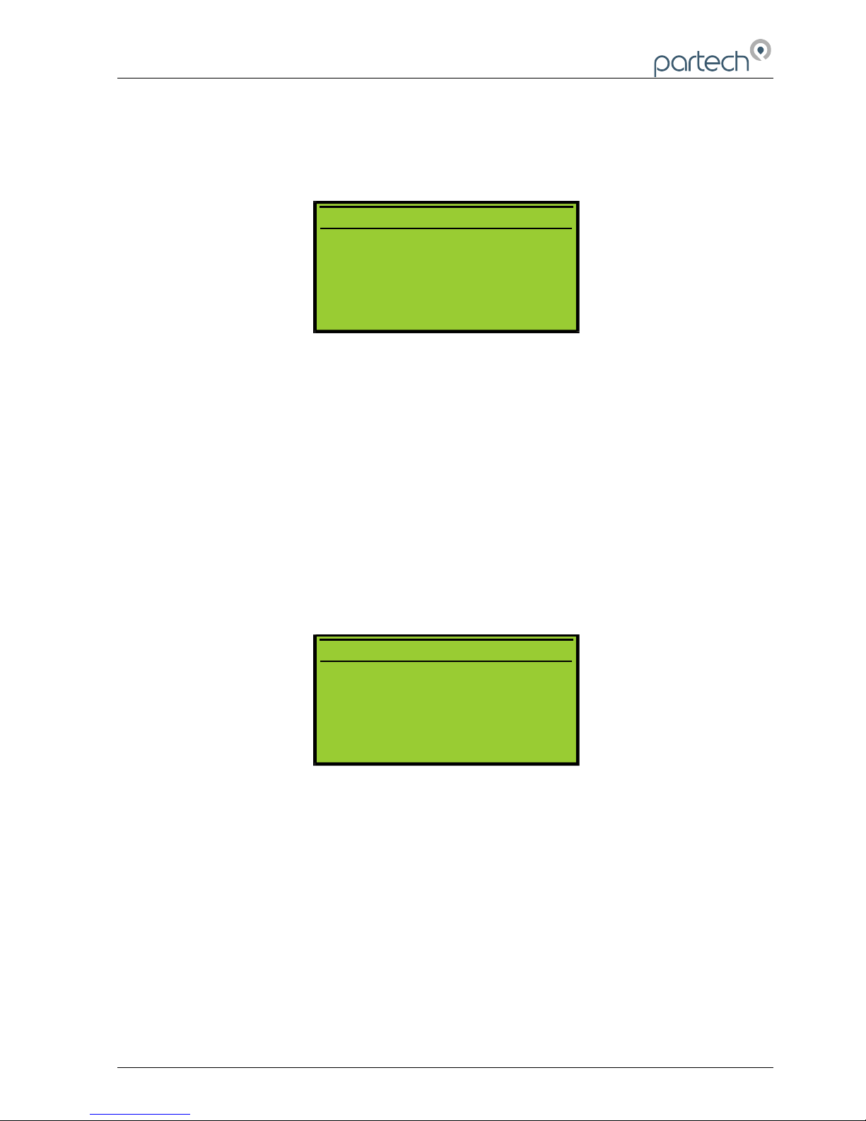
When the New Profile Wizard is selected you will be taken through a series of display
screens that will prompt you to select the correct configuration for your application. The
selections can be modified after creation by editing the profile.
6.1 New Profile Wizard Keys
Once the Create Profile feature has been entered, the MENU key can be used to exit at
any time. Pressing the key moves forward to the next step and pressing the
moves back to the previous step. Pressing the OK key will activate the displayed
function.
6.2 New Profile Wizard Stages
The Create Profile feature guides the user through the configuration of the following
items, for more information about the item, refer to the applicable section of this
manual. (* These stages are shown if the User Defined preset was selected)
172430IM-Iss07.odt 172430IM-Iss07 Issue Date 23/10/2014 Page 17 of 46
7 4 0 P R O F I L E W I Z A R D
U s e t h e 7 4 0 p r o f il e w i z a r d
t o g u i d e y o u t h r o u g h t h e
s e t t i n g u p o f a p r o f i l e .
N E X T
Y
Figure 1 Profile Wizard
7 4 0 P R O F I L E W I Z A R D
U s e t h e 7 4 0 p r o f il e w i z a r d
t o g u i d e y o u t h r o u g h t h e
s e t t i n g u p o f a p r o f i l e .
N E X T
Y
Figure 9 Profile Wizard
7 4 0 P R O F I L E W I Z A R D
T h e w i z a r d c a n b e e x i t e d
b y p r e s s i n g t h e m e n u k e y .
N E X T
Y
Figure 10 Profile Wizard
Page 18

740 Portable Suspended Solids
1. Select Preset
2. Profile Name (up to 21 characters)
3. Profile User (up to 21 characters)
4. Profile Date (dd/mm/yyyy)
5. Measurement Title*
6. Display Units*
7. Display Range*
8. Damping*
On successful completion of the new profile wizard, the calibration of the profile should
be checked, it may be necessary to calibrate the profile. (See Profile Calibration). It
may be necessary to amend some parameters to suit the application.
Page 18 of 46 172430IM-Iss07 Issue Date 23/10/2014
Page 19

740 Portable Suspended Solids
7 Profile Config
7.1 Profile Name
This menu is used to set/edit the profile name. The profile name should be set to
describe the measurement that the profile has been set up for. For example
"Charlestown STW MLSS".
To edit the profile name, use the keys to select a character, and the keys to
change the selected character. When all changes are complete press the OK key to
store the measurement title. To exit without saving changes press the MENU key. The
profile name can be up to 21 characters long.
Note: If the profile name is not set during the creation of the profile it will be
automatically named "Profile x" where x is the profile number.
7.2 Profile User
This menu is used to set/edit the profile user. The profile user can be used to record
the name of the person who set up the profile.
To edit the profile user, use the keys to select a character, and the keys to
change the selected character. When all changes are complete press the OK key to
store the measurement title. To exit without saving changes press the MENU key. The
user name can be up to 21 characters long.
Note: If the profile user is not set during the creation of the profile it will be
automatically named "User x" where x is the profile number.
7.3 Profile Date
The profile date can be set/changed using this menu. The profile date can be used to
record when the profile was created or when the profile was last calibrated.
To edit the profile date, use the keys to select a digit, and the keys to change
the selected digit. When all changes are complete press the OK key to store the
measurement title. To exit without saving changes press the MENU key.
Note: The profile date will be set to a default value if it is not set when the profile
is created. It is possible to enter non-calendar dates - however this will have no
effect on the instruments operation.
172430IM-Iss07.odt 172430IM-Iss07 Issue Date 23/10/2014 Page 19 of 46
Page 20

740 Portable Suspended Solids
7.4 Measurement Title
This menu is used to select the measurement title displayed in measure mode. The
user can select from a list of predefined titles or enter a custom title. To select a
measurement title, use the keys to highlight the required title and press the OK
key. If a predefined title is selected, a small tick will appear next to the selected title. If
the user defined option is selected, a new screen will be displayed which allows editing
of the user defined title.
7.4.1 User Defined Title
To edit the user defined title, use the keys to select a character, and the keys
to change the selected character. When all changes are complete press the OK key to
store the measurement title. To exit without saving changes press the MENU key. The
user measurement title can be up to 21 characters long.
7.5 Display Units
The measurement units displayed in measure mode can be selected using this menu
such that they are appropriate for the measurement being made. The user can select
units from a predefined list, enter custom units (user defined) or switch off the display
of units.
To select the measurement units, use the keys to highlight the required title and
press the OK key. If a predefined title is selected, a small tick will appear next to the
selected title. If the user defined option is selected, a new screen will be displayed
which allows editing of the user defined units.
7.5.1 User Defined Units
To edit the user defined units, use the keys to select a character, and the keys
to change the selected character. When all changes are complete press the OK key to
store the new units. To exit without saving changes press the MENU key. User units
can be up to 4 characters long.
Note: There is no mathematical relationship between FTU and mg/l or g/l. If FTU
are used, Formazin should be used for calibration.
Page 20 of 46 172430IM-Iss07 Issue Date 23/10/2014
Page 21
740 Portable Suspended Solids
7.5.2 Linked Units
The m/g and g/l units are linked such that changing from one to the other will cause a
change in the display range such that the display value is appropriate for the units
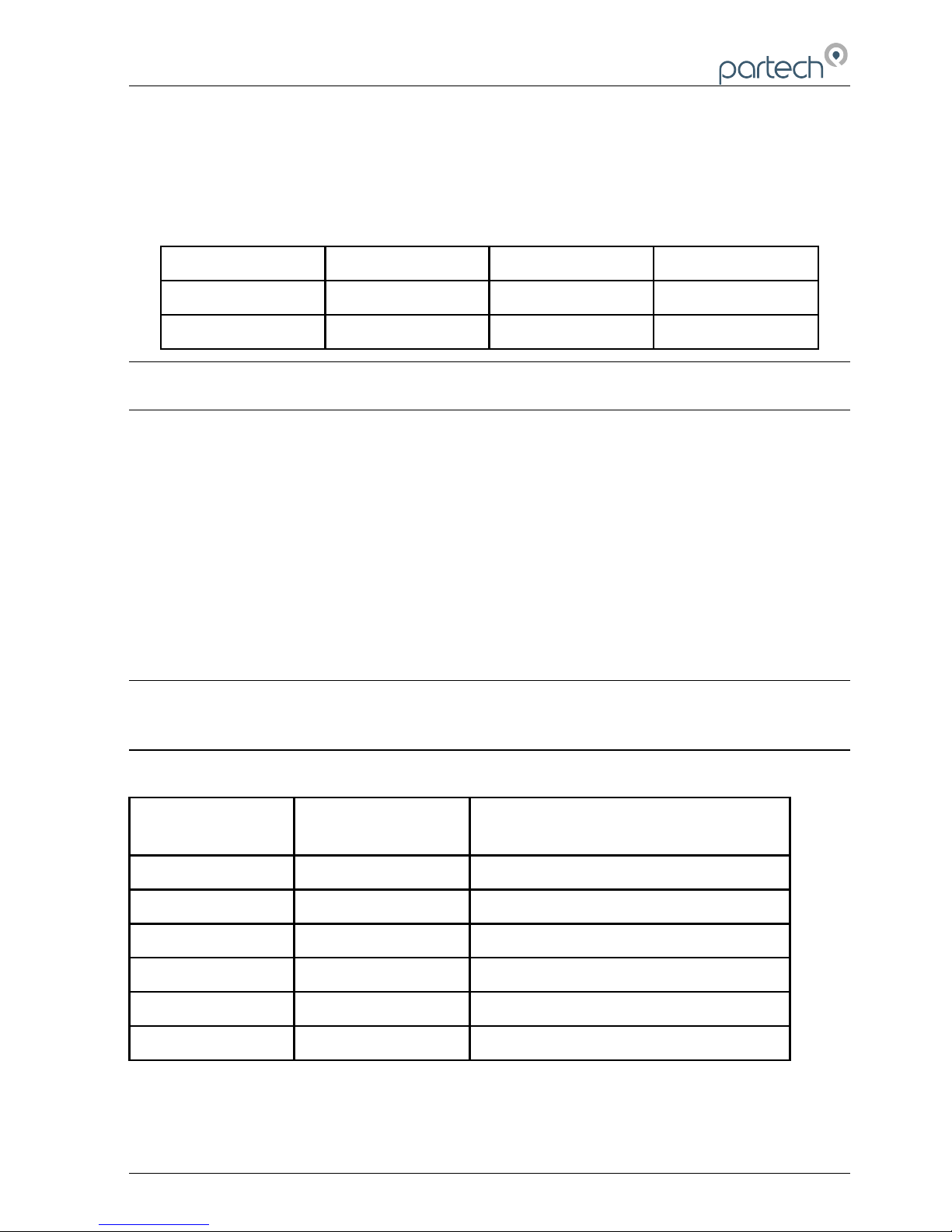
selected. The linked relationship between units and ranges is shown in the table below.
Old Range Old Units Units Changed To: New Range
0 – 20000 mg/l g/l 0 – 20.00
0 – 20.00 g/l mg/l 0 – 20000
Note: Changing from/to any units other than those shown will not effect the
display range.
7.6 Set Damping Range
The 7200 Monitor has the ability to apply damping to the incoming sensor signal such
that a stable measurement value can be displayed. This is essential in applications
where the effluent being monitored produces a fast varying sensor signal such as in an
aeration process.
The response time quoted for each damping rate is indication of the monitor’s
performance when a step change of 0 to 100% occurs on the sensor input. This can be
useful when selecting the damping rate to be used for a particular application.
Note: Pressing the OK key whilst in measure mode causes the display value to
be immediately updated (bypassing damping) - this is very useful when high
levels of damping are used.
Damping Rate Response Time
(Seconds)
Typical Use
Instant 0.2 Instrument Demonstration
Very Fast 1
Fast 10 Final Effluent
Medium 30
Slow 60 Aeration Lane
Very Slow 120
172430IM-Iss07.odt 172430IM-Iss07 Issue Date 23/10/2014 Page 21 of 46
Page 22

740 Portable Suspended Solids
8 Profile Advanced Config
The advanced sensor menu allows the user adjustment of important profile related
settings. These settings can have a major impact on the operation/configuration of the
instrument and should only be altered by experienced users or under the supervision of
Partech.
8.1 Lookup Table Mode
This option is used to set whether the display value lookup table is used. The lookup
table is used to improve the linearity when the characteristics of the effluent being
measured cause the sensor output to be non-linear.
8.2 Adjust X Values
These values along with the Y values are used to perform linearisation on certain
sensor types by means of a lookup table. The X values represent the input values to
the table and the Y values are used to determine the linear output values. For further
information on the use of lookup table linearisation please contact Partech.
8.3 Adjust Y Values
See Adjust X values above.
8.4 Constant A, B, C
Constants A, B and C are used in the calculation of the displayed measurement value.
These values are very important to the operation of the instrument and should only be
changed following advice from Partech.
Page 22 of 46 172430IM-Iss07 Issue Date 23/10/2014
Page 23

740 Portable Suspended Solids
9 Monitor Config
9.1 Bleeper
This option allows the bleeper to be turned on or off, a small tick indicates the current
setting. To change the bleeper setting, use the keys to select the required setting
and press OK. Press MENU to exit the bleeper menu.
9.2 Backlight
The backlight can be set to one of two modes, On after key press (the backlight stays
on for 5 seconds after a key is pressed) or Off. The current backlight mode is indicated
by a small tick, to change the backlight mode, use the keys to select the required
mode and press OK. Press MENU to exit the backlight menu.
9.3 Auto Shutdown
The Auto Shutdown menu allows the user to set whether the instrument automatically
switches itself off. When set to On, the Auto Shutdown feature switches the instrument
off 5 minutes after the last key press thus prolonging battery life. When set to Off, the
instrument will continue operating until switched off by the user or the battery is fully
discharged.
Note: If the instrument has switched off automatically, the user can restore
operation by pressing the ON/OFF key.
9.4 Language
This facility is used to select the operating language of the instrument and is configured
using the list select method of data entry. The 740 Monitor is supplied with a choice of
English and one other language.
9.5 Change Password
The user password used when the instrument is locked and unlocked can be adjusted
using this menu. The first stage in changing the password is to enter the existing
password, which is done using the keys. Once the old password has been
entered, press the OK key to proceed to the next stage, which is the entry of the new
password. The new password can be entered using the keys and pressing the
OK key will store the new password. At any stage whilst the password is being
changed, pressing the MENU key will exit the menu and the old password will be
unchanged.
172430IM-Iss07.odt 172430IM-Iss07 Issue Date 23/10/2014 Page 23 of 46
Page 24

740 Portable Suspended Solids
Note: The factory default password is 1000, if the user password has been
forgotten please contact Partech technical support.
9.6 Monitor Adv Config
9.6.1 Factory Cal Values (1 to 5)
These values are used to store the factory calibration data of the attached sensor. The
only time that these values will need to be accessed is when a replacement sensor is
fitted to the monitor. The new sensor will be supplied with a set of calibration values
that must be entered - failure to do so will affect the calibration and measurement
accuracy of the instrument.
9.7 Load Monitor Defaults
It is sometimes necessary to restore the default values for all the user configurable
parameters such that the instrument is in a known state. To load the monitor defaults,
select Load Monitor Defaults and press OK. To prevent accidental use, the user
password must be entered prior to confirming the operation.
Page 24 of 46 172430IM-Iss07 Issue Date 23/10/2014
Page 25

740 Portable Suspended Solids
10 Profile Calibration
10.1 Calibration – General
Calibration of the 740 Monitor is very important, errors in the calibration process will
effect the measurement performance of the instrument. The following section describes
the various aspects of calibrating the 740 Monitor and has been written with the
understanding that the user has knowledge of the measurement being made.
Any containers used to store calibration samples should be cleaned prior to use. This is
particularly important when performing the zero point calibration on a low range
application.
The most accurate method of calibration is using a primary standard, i.e. calibration in
the actual solution against a laboratory result. Where this is not possible or where the
trend of the reading is necessary rather than an absolute value it is acceptable to use a
secondary standard.
Note: Each profile must be separately calibrated, ensure that the required profile
has been selected prior to calibration.
10.2 Methods of Calibration
10.2.1 Primary Standard
This method of calibration will give the best results however it does require the use of a
laboratory to carry out a gravimetric analysis of the calibration solution. The result of
the gravimetric analysis is used as the calibration value.
10.2.2 Secondary Standard
In cases where it is not possible to carry out calibration using a primary standard,
secondary standards such as Fullers Earth or Formazin can be used. It is important to
remember however that instruments calibrated in this way will give results based on the
secondary standard used and this will differ from the results of a gravimetric analysis.
A guide to the preparation of Fullers Earth and Formazin solutions is located at the
back of this manual.
172430IM-Iss07.odt 172430IM-Iss07 Issue Date 23/10/2014 Page 25 of 46
Page 26
740 Portable Suspended Solids
10.2.3 Calibration Intervals
The 740 Monitor and Sensor combination once calibrated will require calibration
checking/re-calibration at 3-6 monthly intervals, however this does depend on the
application. The calibration of the instrument can be effected by seasonal variations in
the measured effluent, however only knowledge of the application can determine the
re-calibration interval required.
10.3 Preparing for Calibration
To ensure that calibration will be as successful as possible the following should be
observed:
1. Clean the whole sensor and at least 1 metre of cable.
2. The zero solution should be clean settled tap water for high range measurements
and freshly distilled or de-mineralised water for low range measurements.
3. A calibration solution will be required, ideally this should be greater than 75% of
the intended measurement range.
10.4 Calibration Wizard
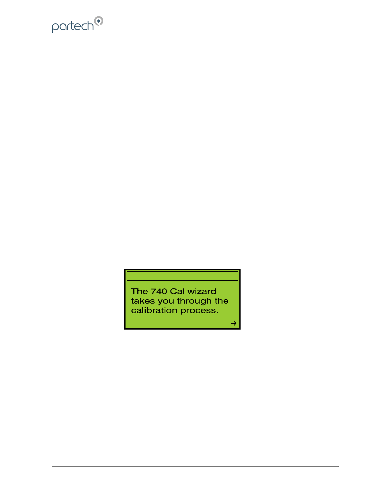
The 740 Calibration Wizard guides the user through the important process of
calibrating the instrument. Once the setup wizard has been completed, the instrument
should respond to changes to the sensor signal (for example placing the sensor into
the zero solution and then into the calibration solution). Although the instrument is
responding, the factory default calibration values are used until user calibration is
carried out.
Before using the calibration wizard, the guideline described in the preparation for
calibration section above should be observed. Also ensure that the correct display
range and units have selected.
Page 26 of 46 172430IM-Iss07 Issue Date 23/10/2014
7 4 0 C A L W I Z A R D
N E X T
Figure 11 Calibration Wizard
Page 27
740 Portable Suspended Solids
10.4.1 Cal Wizard Keys
Once the calibration wizard has been entered, the MENU key can be used to exit at
any time. Pressing the key moves forward to the next step and pressing the
moves back to the previous step. Pressing the OK key will activate the displayed
activity.
10.4.2 Cal Wizard Stages
The Cal Wizard guides the user through the process of setting the instrument zero and
span. For more information about setting zero and span, refer to the applicable section
of this manual.
10.5 Set Zero
This menu is used to set the instrument display zero for the attached sensor. To zero
the instrument, go to the Calibration menu, select Set Zero and press the OK key.
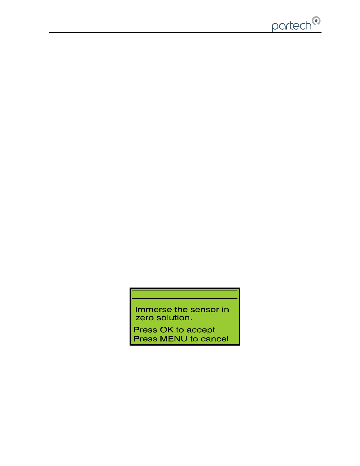
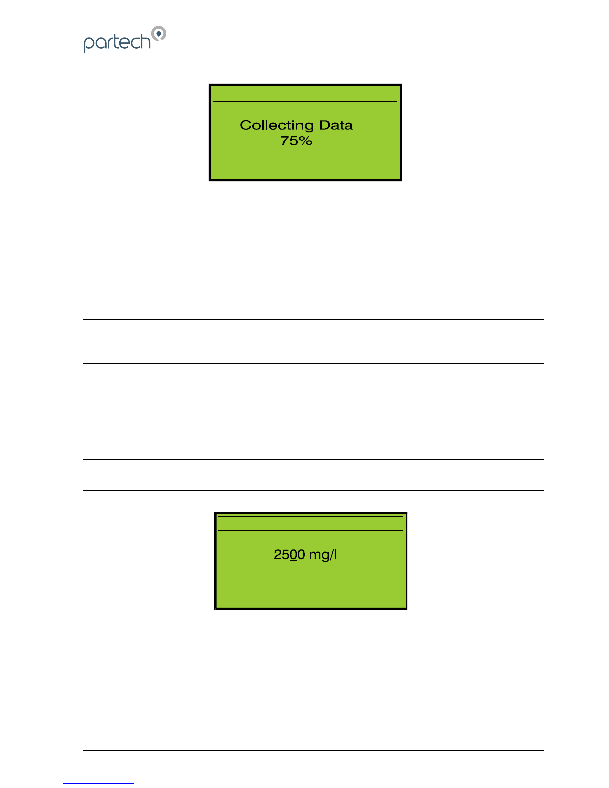
Immerse the sensor into the zero solution and press the OK key. The 740 Monitor
collects data for the zeroing operation for approximately 5 seconds to ensure that the
zero is set accurately. During this period do not move the sensor, as this could effect
the zero operation. If the zeroing process is successful, the monitor will return to
measure mode and the display value will be zero. If a problem occurs during the
zeroing operation, an error message will be displayed and the monitor will return to the
Calibration menu.
172430IM-Iss07.odt 172430IM-Iss07 Issue Date 23/10/2014 Page 27 of 46
Z E R O
Figure 12 Zero - Preparation
Page 28
740 Portable Suspended Solids
Z E R O
Figure 13 Zero - Collecting Data
10.6 Set Span
The Set Span function is used to set the calibration point for the instrument, which is
used in the calculation of the displayed value. To calibrate the instrument, go to the
Calibration menu, select Set Span and press the OK key.
Note: If an online calibration is being carried out, whilst in measure mode check
that the display value is stable – it may be necessary to increase the damping
level to stabilise the display value.
10.6.1 Step 1. Calibration Value Entry
The calibration value can be set to a value between 3 – 100% of the currently selected
measuring range using the keys. This value should be set to the value of the
calibration solution. Once the correct value has been set press the OK key. Pressing
the MENU key will exit the Set Span operation.
Note: The calibration value can only be set between 3 to 100% of the display
range.
10.6.2 Step 2. Calibrating
As indicated by the on display instructions, immerse the sensor into the calibration
solution and press the OK key. The 740 Monitor collects data for the spanning
operation for approximately 10 seconds to ensure that the span is set accurately.
Page 28 of 46 172430IM-Iss07 Issue Date 23/10/2014
C A L I B R A T E
P r e s s M E N U t o c a n c e l
P r e s s O K t o a c c e p t
U s e t o s e t v a l u e
-
Figure 14 Set Span –Calibration Value Entry
Page 29
740 Portable Suspended Solids
During this period do not move the sensor, as this could effect the span operation. If
the spanning process is successful, the monitor will return to measure mode and the
display value should be correct for the calibration solution. If a problem occurs during
the spanning operation, an error message will be displayed and the monitor will return
to the Calibration menu.
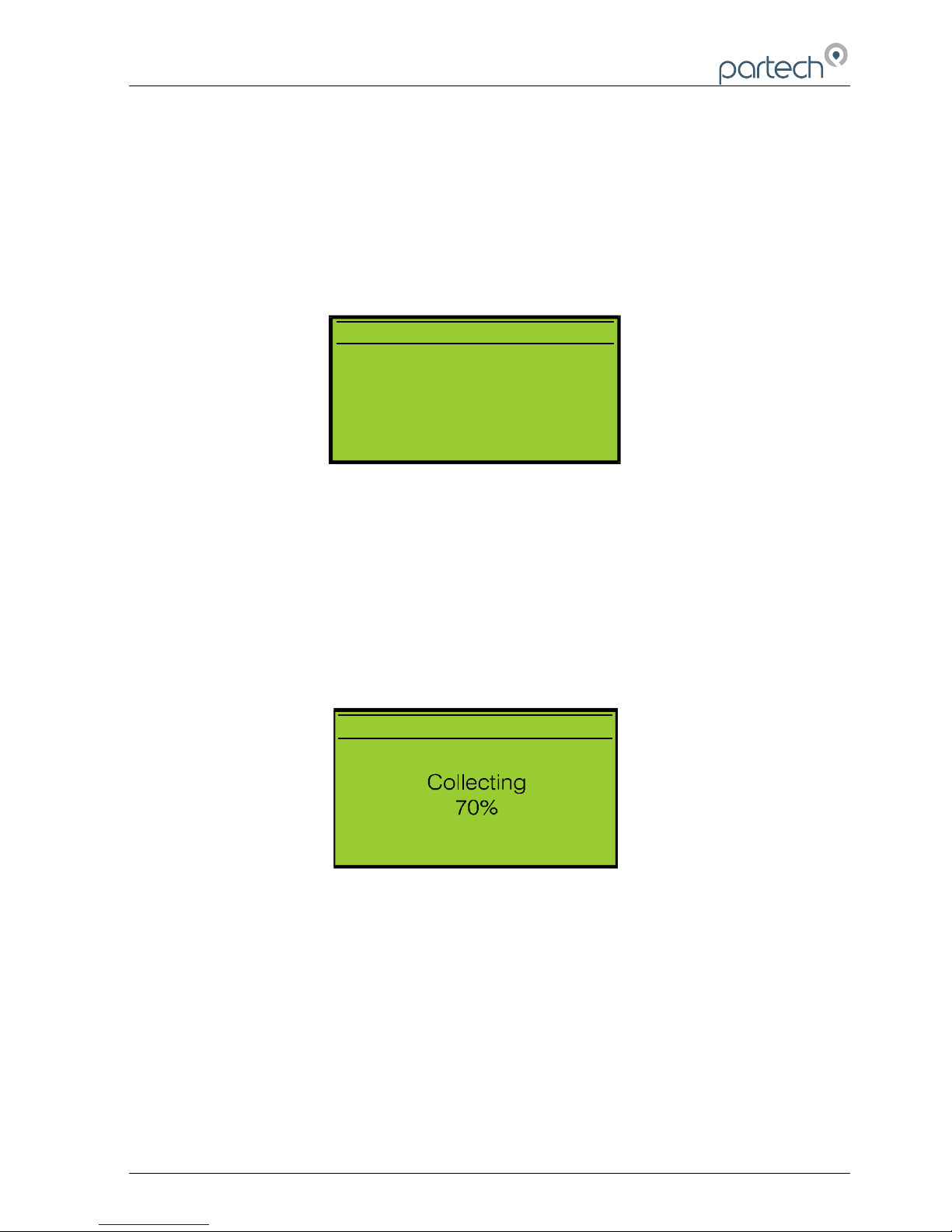
C A L I B R A T E
I m m e r s e t h e s e n s o r i n
c a l b r a t i o n s o l u t i o n .
P r e s s O K t o a c c e p t
P r e s s M E N U t o c a n c e l
Figure 15 Set Span - Preparation
C A L I B R A T E
Figure 16 Set Span – Data Collection
10.7 Take Sample
The Take Sample and Enter Sample Result facilities are provided to allow calibration to
be carried out retrospectively based upon stored information. An example of this is
where the value of the calibration solution is not known at the time of calibration and an
172430IM-Iss07.odt 172430IM-Iss07 Issue Date 23/10/2014 Page 29 of 46
Page 30

740 Portable Suspended Solids
estimated value was used to set the instrument span. The take sample menu is used to
store the sensor signal relating to the calibration solution for later use.
From the Calibration menu, select Take Sample and press the OK key. With the sensor
immersed in the calibration solution, (The display value must be stable – this can be
checked when in measure mode) press the OK key. The 740 Monitor collects data for
the take sample operation for approximately 10 seconds, during this period do not
move the sensor. If the take sample process is successful, the monitor will return to
measure mode. If a problem occurs during the zeroing operation, an error message will
be displayed and the monitor will return to the Calibration menu.
10.8 Enter Sample Result
When the take sample operation has been carried out, and the correct value for the
calibration solution is known, the new calibration value can be entered using the Enter
Sample Result menu.
To enter the new calibration value, from the calibration menu, select the Enter Sample
Result menu and press the OK key. The calibration value can be set to a value
between 3 – 100% of the currently selected measuring range using the keys.
This value should be set to the value of the calibration solution. Once the correct value
has been set press the OK key. Pressing the MENU key will exit the Set Span
operation.
Note: The calibration value can only be set between 3 –100% of the display
range.
Page 30 of 46 172430IM-Iss07 Issue Date 23/10/2014
Page 31

740 Portable Suspended Solids
11 Information
11.1 Profile Information
Details of the current (active) profile are displayed for user reference.
11.2 Software Version
This display indicates the software version and serial number of the instrument and is
useful for recording and problem diagnosis.
11.3 Contact Information
This display provides contact information for Partech (Electronics) Ltd.
11.4 Battery Status
This display provides information on the charge status of the battery, this includes
battery voltage, percentage charged and whether a charger is connected to the monitor
11.5 Sensor Input
This display provides basic diagnostic information about the sensor performance. The
information can assist in the resolution of monitoring problems, it is likely that Partech
will request information from this display when providing technical support.
172430IM-Iss07.odt 172430IM-Iss07 Issue Date 23/10/2014 Page 31 of 46
Page 32
740 Portable Suspended Solids
12 Instrument Security
The 740 Monitor can be locked to prevent unauthorised access to the configuration
menus by using a password. The user password is a 4 digit number that can be set to
any value the user chooses. When supplied new, the user password is set to 1000, we
recommend that this is changed when the instrument is installed.
Note: The factory default password is 1000, if the user password has been
forgotten please contact Partech technical support.
12.1 Lock Instrument
The user will be prompted for the entry of the user password, when entered correctly
the instrument will be locked. The instrument can only be locked with the correct user
password thus avoiding accidental/unauthorised locking.
Once the instrument is locked, the user will be asked for the password when attempting
to carry out any operation other than:
• Switching the monitor ON or OFF
• Selecting a previously configured profile
12.2 Change Password
The method of changing the user password is described in the monitor configuration
section of this manual.
Page 32 of 46 172430IM-Iss07 Issue Date 23/10/2014
Page 33

740 Portable Suspended Solids
13 Error Messages
When the instrument detects an error condition, an error message will be displayed. All
the error messages are described below:
13.1 Measurement
13.1.1 Display Over Range
Calculated display value greater than selected display range maximum, either change
display range or check calibration is correct.
13.1.2 Display Under Range
Calculated display value less than selected display range minimum, check calibration
13.2 Sensor
13.2.1 No Sensor
No sensor detected on input to monitor, if sensor is connected and wiring is okay either
sensor fault or monitor fault.
13.2.2 Sensor Low Limit
Sensor input signal is too low possible, sensor fault.
13.2.3 Sensor High Limit
Sensor input signal is too high possible, sensor fault.
Calibration
13.2.4 Not Available - Sensor Fault
If one of the above sensor faults is present, it is not possible to perform a calibration.
Clear the sensor fault and try again.
13.2.5 Sensor Input Too High (Set Zero)
The data collected for the zero operation was above the allowed maximum for a zero
operation. This can be caused by a dirty zero solution, fouling on the sensor or a fault
with the sensor.
13.2.6 Sensor Input Too Low (Set Zero)
The data collected for the zero operation was below the allowed minimum for a zero
operation. This generally indicates that the sensor is faulty.
13.2.7 Sensor Input Too Low (Set Span)
The data collected for the calibration operation was below the allowed minimum for the
span to be set. This occurs when sensor signal in the calibration solution is too close to
172430IM-Iss07.odt 172430IM-Iss07 Issue Date 23/10/2014 Page 33 of 46
Page 34

740 Portable Suspended Solids
the sensor signal in the zero solution. This can be caused by too clear a calibration
solution, or a fault with the sensor.
Page 34 of 46 172430IM-Iss07 Issue Date 23/10/2014
Page 35
740 Portable Suspended Solids
14 Battery Charging
14.1 Battery
The instrument contains a Nickel Metal Hydride battery pack that supplies it power for
operation. This type of battery has been selected for its ease of use - it does not have
to be fully discharged prior to charging. It is therefore possible to "top up" the battery
charge as and when required, this is particularly useful prior to the instrument being
used for a long period.
14.2 Charger
The 740 Monitor can be charged using either the mains or car charger available from
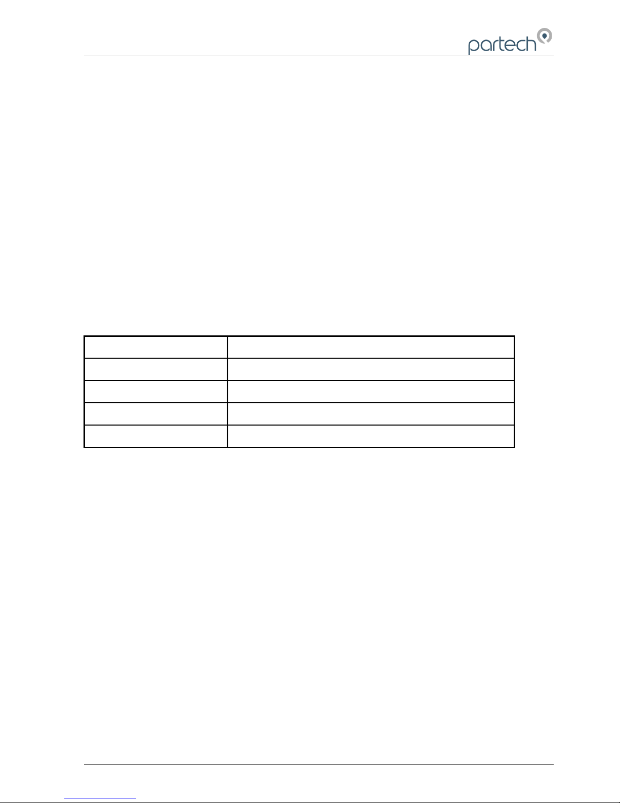
Partech. When connected to the monitor, the charging LED gives a visual indication of
charging status.
Charging LED Colour Status
Unlit Charger not connected or switched off
Red Charging
Orange Nearly charged
Green Fully charged
172430IM-Iss07.odt 172430IM-Iss07 Issue Date 23/10/2014 Page 35 of 46
Page 36

740 Portable Suspended Solids
15 Maintenance
In normal operation the instrument requires no routine maintenance other than an
occasional clean with a damp cloth.
15.1 Sensor Replacement
Should it be necessary to replace the sensor the following procedure should be used:
1. Unscrew the eight screws in the back of the monitor.
2. Carefully separate the two halves of the monitor, when the two halves are
approximately 30mm apart, unplug the keypad connector and completely remove
the front of the monitor.
3. Locate the sensor terminals, unscrew the four terminals and remove the sensor
wires. Slacken the cable gland and remove the sensor cable.
4. Feed the replacement sensor cable through the cable gland and connect the
sensor wires as indicated on the circuit board. Ensure that the terminal screws are
securely tightened.
5. Plug the keypad connector into its socket ensuring that it is properly aligned.
Replace the monitor front and refit the eight retaining screws.
6. Switch the monitor on and following the instructions supplied with the replacement
sensor enter the its factory calibration data.
7. The instrument is now ready for use.
Page 36 of 46 172430IM-Iss07 Issue Date 23/10/2014
Page 37
740 Portable Suspended Solids
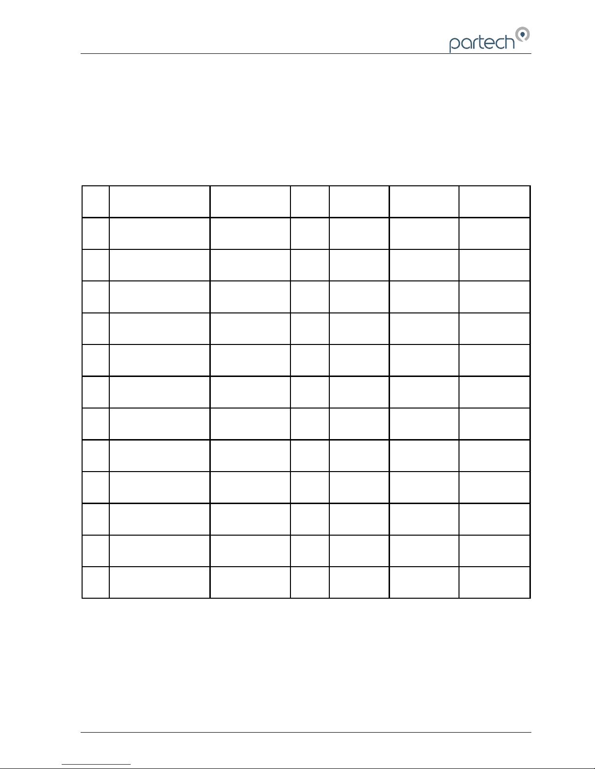
16 Presets Measurements
The configuration of each preset measurement is shown below:
Name/Type
Measurement
Title
Units Display
Range
Damping
Rate
Calibration
Value
1 STW Final Effluent
0 - 100 mg/l
Final Effluent mg/l 0 - 200.0 Fast 100.0
2 STW NAS
0 - 1000 mg/l
M.L.S.S mg/l 0 - 2000 Fast 1000
3 STW NAS
0 - 10000 mg/l
M.L.S.S mg/l 0 - 20000 Fast 10000
4 Formazin
0 - 100 FTU
Turbidity FTU 0 - 200.0 Very Fast 100.0
5 Formazin
0 - 1000 FTU
Turbidity FTU 0 - 2000 Very Fast 1000
6 Formazin
0 - 4000 FTU
Turbidity FTU 0 - 20000 Very Fast 4000
7 Fullers Earth
0 - 100 mg/l
Suspended
Solids
mg/l 0 - 200.0 Fast 100.0
8 Fullers Earth
0 - 1000 mg/l
Suspended
Solids
mg/l 0 - 2000 Fast 1000
9 Fullers Earth
0 - 10 g/l
Suspended
Solids
g/l 0 - 20.00 Fast 10.00
10 Fullers Earth
0 - 20 g/l
Suspended
Solids
g/l 0 - 20.00 Fast 10.00
11 Milk (Full Fat)
0 - 10 %
Suspended
Solids
% 0 - 20.00 Fast 10.00
12 User Defined
Suspended
Solids
mg/l 0 - 2000 Fast 1000
172430IM-Iss07.odt 172430IM-Iss07 Issue Date 23/10/2014 Page 37 of 46
Page 38
740 Portable Suspended Solids
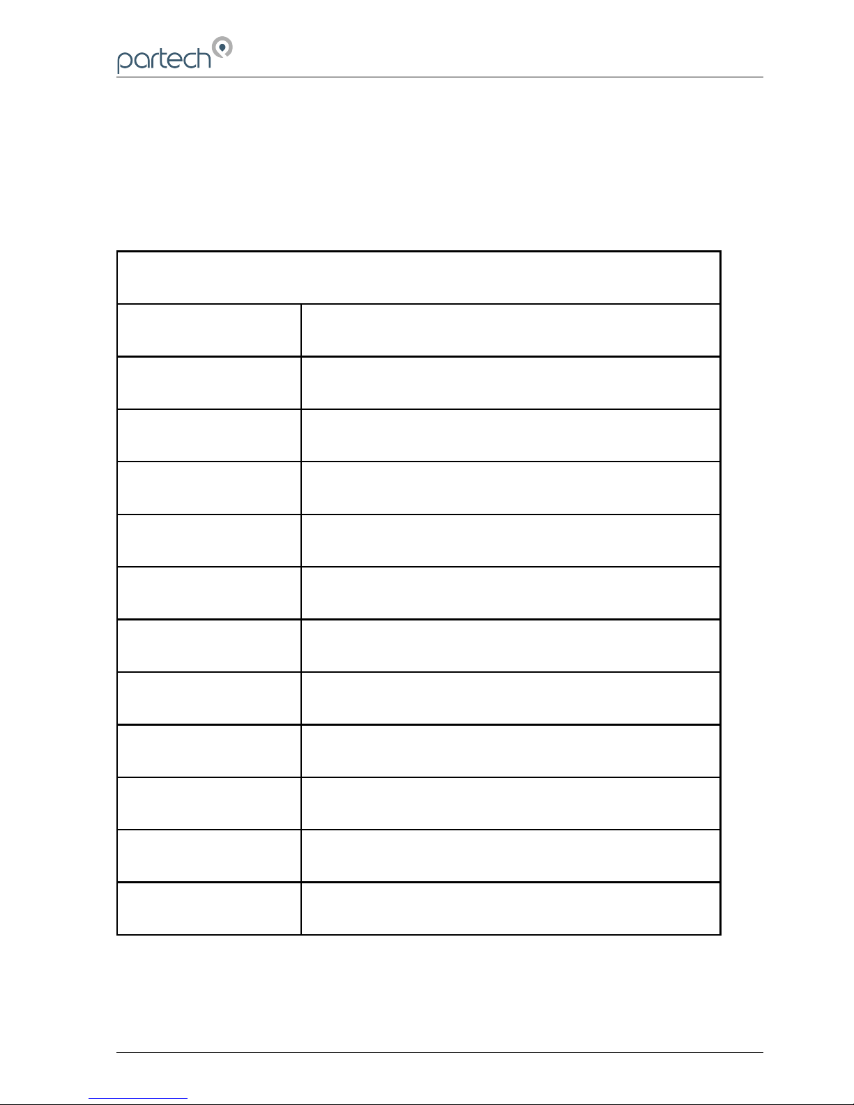
17 User Profile setup Record
The form below can be used to record the configuration of a profile
740 Monitor Profile Record
Profile Number
Profile Name
Profile User
Profile Date
Measurement Title
Units
Display Range
Damping Rate
Calibration Value
Constant A
Constant B
Constant C
Page 38 of 46 172430IM-Iss07 Issue Date 23/10/2014
Page 39

740 Portable Suspended Solids
18 Technical Support
Technical Support is available by phone, fax, or email, the details of which are shown
below.
• Phone: +44 (0) 1726 879800
• Fax: +44 (0) 1726 879801
• Email: [email protected]
• Website: www.partech.co.uk
To enable us to provide quick and accurate technical support please have the following
information ready when you contact us:
• Serial Number or original purchase details
• Sensor Type, and Serial Number
• Application details
• Description of fault
18.1 Returning Equipment for Repair
If equipment needs to be returned to Partech for repair or service the following address
should be used:
SERVICE DEPARTMENT
PARTECH INSTRUMENTS
ROCKHILL BUSINESS PARK, HIGHER BUGLE
ST AUSTELL, CORNWALL, PL25 3NN
UNITED KINGDOM
Please include the following information with the returned equipment. Also ensure that
sensors are adequately protected for transportation (Advice on packing can be
provided by our service department).
• Contact name and phone number
• Return address for equipment
• Description of fault or service required
• Any special safety precautions because of nature of application
172430IM-Iss07.odt 172430IM-Iss07 Issue Date 23/10/2014 Page 39 of 46
Page 40

740 Portable Suspended Solids
19 Technical Specification (should be last section)
19.1 Electrical Information
Power Supply..................................Internal Rechargeable Battery Pack
Charge Input...................................11 - 14 VDC (2.1mm Plug centre positive)
Partech Charger..............................90-264 VAC (47-63 Hz) Universal Supply
European, US or UK Plug Style
EMC Conformity..............................EN 50081, EN 50082
Adjustment......................................via Membrane Keypad
Operating Temperature...................-20 to + 60° C
Display............................................5 Digit, Grapghical SmartFluid™ LCD
19.2 Physical Features
Enclosure Material..........................ABS
Enclosure Dimensions....................224 × 106 × 39 mm (h × w × d)
Weatherproof Rating.......................IP65
Weight (no sensor)..........................0.5 kg
19.3 Software Features
Number of User Profiles..................10
Preset Calibrartions.........................Formazin
Fulller’s Earth
Normal Activated Sludge
Milk (Full Fat)
Units of Measurement.....................mg/l
g/l
ppm
FTU
NTU
%SS
User Defined
Display Ranges...............................0-20.00
0-200.0
0-2000
0-20000
Auto Power Off................................5 mins
172430IM-Iss07.odt 172430IM-Iss07 Issue Date 23/10/2014 Page 40 of 46
Page 41
740 Portable Suspended Solids
20 Preparation of Fullers Earth
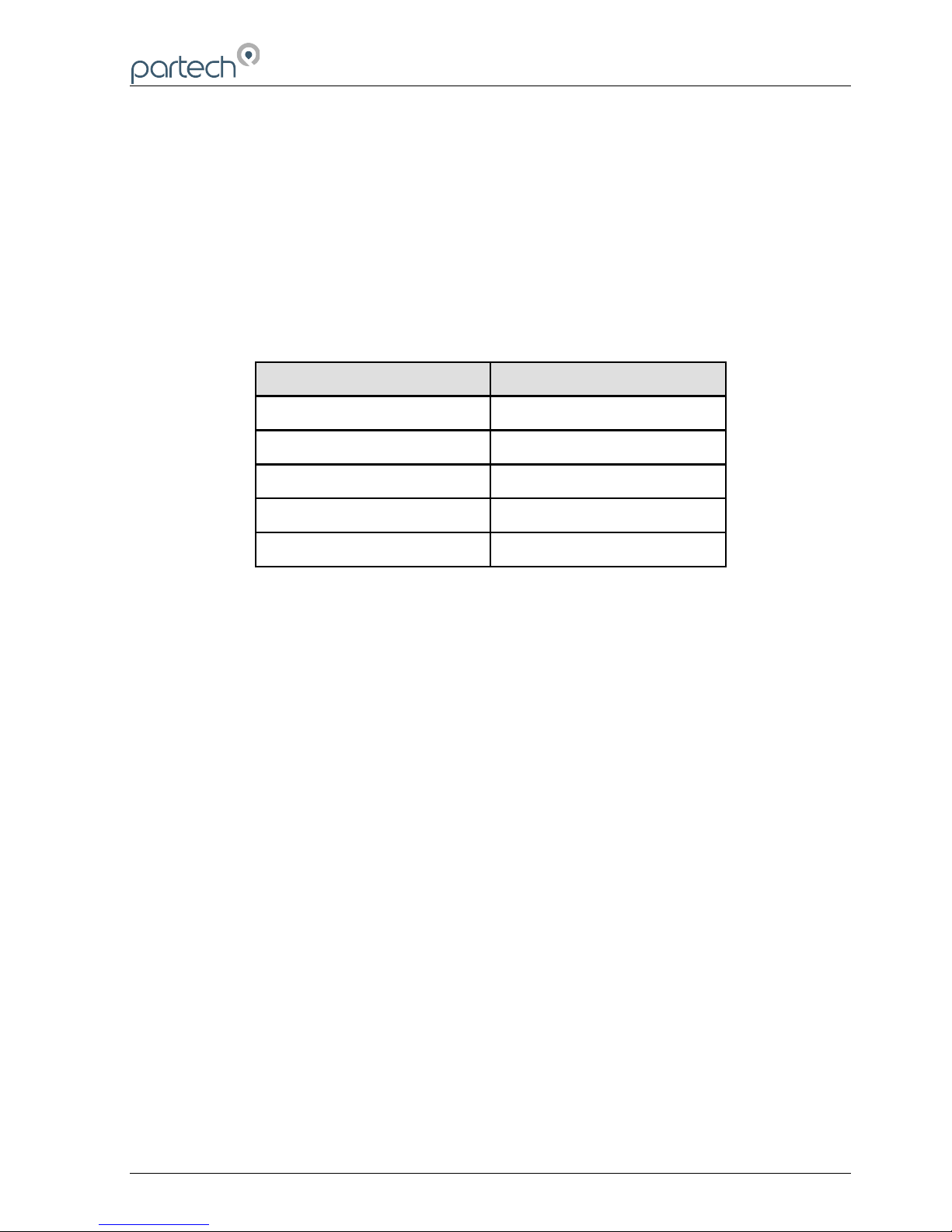
The Fuller's Earth is supplied in a sealed 20g package, the package contains sufficient
to make a 20,000 mg/l (20 g/l) solution when combined with 1 litre of water. Alternate
solutions can be obtained by increasing the amount of water used as shown in the
table below.
Solution Required (g/l)
Add pack to water (litres)
2.5 8.0
5.0 4.0
10.0 2.0
20.0 1.0
40.0 0.5
The following points should be observed when preparing and using Fullers Earth
solutions:
The water used should be freshly distilled or de-mineralised
Ensure the container used for the solution is clean
During preparation and use, keep the solution covered to prevent contamination
When using the solution it must be continually stirred to ensure accurate and
consistent measurements and to prevent settling
172430IM-Iss07 Issue Date 23/10/2014 Page 41of 46
Page 42

740 Portable Suspended Solids
21 Preparation of Formazin Turbidity Standard
21.1 Health & Safety Precautions
The chemicals used when following this procedure are harmful, therefore the correct
safety precautions must be carried out. During handling, avoid inhalation and contact
with the eyes or skin. Wash hands thoroughly after use. Refer to the data sheets for
further details of the chemicals used.
21.2 Method of Preparation
he preparation of a Formazin Turbidity Standard should be carried out with great care.
Absolute cleanliness should be observed at all times to avoid any contamination of the
solution.
All water used should be freshly distilled or de-mineralised. During preparation and use,
keep the solution covered to prevent contamination.
Dissolve the Hydrazinium Sulphate 10g into 1 litre of water. Stir the solution
thoroughly.
Dissolve the Hexamine 100g into 1 litre of water. Stir the solution thoroughly.
Pour the above solutions into a 2.5 litre Winchester or similar type amber
glass bottle and mix thoroughly. Allow the mixture to stand undisturbed for 24
hours at 25C. The resultant solution will have a turbidity of 4000 FTU.
Prior to use the standard should be mixed thoroughly. i.e. before pouring out
the standard, shake the bottle well.
21.3 Preparation of Dilution's
The 4000 FTU standard can be used to prepare solutions of lower values by diluting
with water. The formula below can be used to calculate the ratio of water to 4000 FTU
standard to produce a solution of the required value.
WA
4000
1
W = parts water to 1 part 4000 FTU standard
A = Required FTU value
172430IM-Iss07.odt 172430IM-Iss07 Issue Date 23/10/2014 Page 42 of 46
Page 43

740 Portable Suspended Solids
21.4 Calibration
When Formazin solutions are used for calibration/testing of sensors, sufficient solution
is required such that the sensor is completely immersed. When using light scatter
sensors it is important that the sensor is positioned away from the sides and bottom of
the container to prevent the light being reflected.
21.5 Storage Life
The turbidity standard should be stored in the Winchester bottle and kept in a cool dark
place. The bottle should be labelled to identify its content and also the date of
preparation should be recorded. The 4000 FTU standard has a shelf life of one year
after which it should be discarded and a fresh solution should be prepared.
Solutions made by diluting the 4000 FTU standard should also be stored in suitably
labelled amber glass bottles and kept in a cool dark place. Solutions above 400 FTU
have a shelf life of one month after which they should discarded. Solutions below 400
FTU should be prepared from the 4000 FTU standard daily.
Solutions can be used outside of the storage lives specified above but any results
taken must acknowledge this and be accepted as less accurate. When using solutions,
watch for flocculation (the particles in the solution will appear to link together), if this
occurs discard the solution and prepare a fresh standard.
172430IM-Iss07 Issue Date 23/10/2014 Page 43of 46
Page 44

740 Portable Suspended Solids
22 Declaration of CE Conformity
The manufacturer Partech Instruments
Address Rockhill Business Park
Higher Bugle
St Austell
Cornwall
PL26 8RA
herewith declares that the product
Part Number 172030
Product 740 Monitor
is in conformity with the standards noted below:
EN 50081-1 (1992) EMC Generic Emission Standard
Residential, commercial & light industry
EN 50082-1 (1994) EMC Generic Immunity Standard
Residential, commercial & light industry
following the provisions of European Directives:
89/336/EEC EMC Directive:
Electromagnetic Compatibility
73/23/EEC Low Voltage Directive:
Electrical equipment designed for use within
certain voltage limits
The CE Symbol confirms that this product conforms with the above mentioned norms
and regulations.
Roger Henderson, Technical Director, August 24, 2001
172430IM-Iss07.odt 172430IM-Iss07 Issue Date 23/10/2014 Page 44 of 46
Page 45

740 Portable Suspended Solids
172430IM-Iss07 Issue Date 23/10/2014 Page 45of 46
Page 46
Partech Instruments
Rockhill Business Park, Higher Bugle, St Austell, Cornwall, PL26 8RA, UK
Tel: +44(0)1726 879800
Email: [email protected] Web: www.partech.co.uk
 Loading...