

Page 1

INSTRUCTION MANUAL
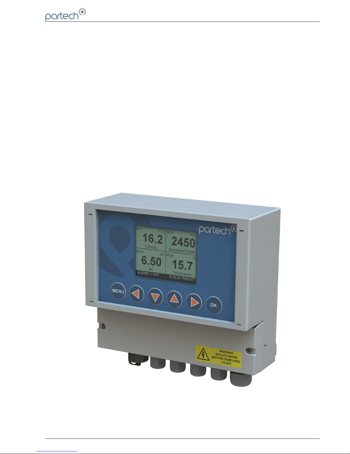
7300w² Monitor
Issue 22
Page 2

7300w² Monitor Instruction Manual
** This page is intentionally left blank **
Page 2 of 46 224081IM Issue 22 Issue Date 27/03/2018
Page 3

7300w² Monitor Instruction Manual
Table of Contents
1 Foreword.......................................................................................................................................................................... 5
1.1 Manual Conventions................................................................................................................................................ 6
1.2 WaterWatch² Trademark.......................................................................................................................................... 6
1.3 Scope of Manual...................................................................................................................................................... 6
1.4 External Sensors..................................................................................................................................................... 6
2 Safety Precautions........................................................................................................................................................... 7
2.1 General.................................................................................................................................................................... 7
2.2 Electrical Installation................................................................................................................................................ 7
2.3 Operating................................................................................................................................................................. 7
2.4 Service and Maintenance........................................................................................................................................ 8
2.5 End of Life Disposal................................................................................................................................................. 8
3 Installation....................................................................................................................................................................... 9
3.1 Mechanical Installation............................................................................................................................................ 9
3.2 Installation Considerations...................................................................................................................................... 9
3.3 Fixings................................................................................................................................................................... 10
3.4 Electrical Installation.............................................................................................................................................. 11
3.4.1 Gland Configuration.................................................................................................................................... 11
3.4.2 DC Power Connections.............................................................................................................................. 12
3.4.3 AC Power Connections............................................................................................................................... 12
3.4.4 Sensor Connections................................................................................................................................... 12
3.4.5 Extending Sensor Cables........................................................................................................................... 13
3.4.6 Relay Outputs (Alarms).............................................................................................................................. 14
3.4.7 Analogue Outputs....................................................................................................................................... 14
4 Basic Operation.............................................................................................................................................................. 17
4.1 Keys and Screen Navigation................................................................................................................................. 17
4.1.1 Menu Button............................................................................................................................................... 17
4.1.2 Navigation Buttons...................................................................................................................................... 17
4.1.3 OK Button................................................................................................................................................... 17
4.2 Default Configuration............................................................................................................................................. 17
4.2.1 Electrodes, Sensors and Measurements Definition....................................................................................17
4.3 Measurement Display Mode.................................................................................................................................. 17
4.3.1 Trending Display Mode............................................................................................................................... 18
5 System Configuration..................................................................................................................................................... 19
5.1 Monitor Config Menu............................................................................................................................................. 19
5.1.1 Bleeper........................................................................................................................................................ 19
5.1.2 Backlight..................................................................................................................................................... 20
5.1.3 Contrast...................................................................................................................................................... 20
5.1.4 Language.................................................................................................................................................... 20
5.1.5 Set Time/Date............................................................................................................................................. 20
5.1.6 Enable Service Mode.................................................................................................................................. 21
5.2 Expansion Config.................................................................................................................................................. 21
5.2.1 Expansion Status........................................................................................................................................ 21
5.2.2 Add Expansion............................................................................................................................................ 21
5.2.3 Expansion Box Config Menu...................................................................................................................... 22
5.2.4 Changing Expansion Modbus Address....................................................................................................... 22
5.2.5 Expansion Box PN224920 – Single Analogue Input................................................................................... 23
5.3 Sensor Config........................................................................................................................................................ 24
5.3.1 Sensor Status............................................................................................................................................. 24
5.3.2 Add Sensor................................................................................................................................................. 24
5.3.3 Sensor Config............................................................................................................................................. 24
5.3.4 Sensor Removal......................................................................................................................................... 25
5.3.5 Changing Sensor Modbus Address............................................................................................................25
5.3.6 Default Modbus Addresses......................................................................................................................... 26
5.3.7 Measurement Config.................................................................................................................................. 26
224081IM Issue 22 Issue Date 27/03/2018 ` Page 3 of 46
Page 4

7300w² Monitor Instruction Manual
5.3.8 Measurement Status................................................................................................................................... 26
5.3.9 Add Measurement.......................................................................................................................................27
5.3.10 Measurement Removal............................................................................................................................. 27
5.4 Measurement (Specific) Config............................................................................................................................. 27
5.4.1 Display Position.......................................................................................................................................... 27
5.5 Alarm Config (Relay outputs).................................................................................................................................28
5.5.1 Alarm Addressing with Expansion Boxes.................................................................................................... 29
5.6 Output Config (Analogue Outputs)........................................................................................................................ 30
5.6.1 Output Addressing with Expansion Boxes..................................................................................................31
5.7 Information............................................................................................................................................................. 31
5.7.1 Software Version.........................................................................................................................................31
5.7.2 Contact Information.................................................................................................................................... 31
5.8 Lock Config............................................................................................................................................................ 32
5.8.1 Lock Monitor............................................................................................................................................... 32
5.8.2 Change Password...................................................................................................................................... 32
5.8.3 Set Auto Lock..............................................................................................................................................32
5.9 Logging.................................................................................................................................................................. 33
5.9.1 Logging Status............................................................................................................................................ 33
5.9.2 Download Logged Data to USB.................................................................................................................. 33
5.9.3 Logging Interval.......................................................................................................................................... 33
5.9.4 Logging Mode............................................................................................................................................. 33
5.9.5 Logging Reset............................................................................................................................................. 33
5.9.6 Locating the Log File.................................................................................................................................. 33
6 Service Mode................................................................................................................................................................. 35
6.1 Access to Service Mode........................................................................................................................................ 35
6.1.1 Enable Factory Mode.................................................................................................................................. 35
6.1.2 Monitor Config Adv......................................................................................................................................35
6.1.3 Output 0/4mA and 20mA Offset.................................................................................................................. 36
7 Menu Tree...................................................................................................................................................................... 38
8 Maintenance.................................................................................................................................................................. 40
8.1 On-Board Battery Backup Replacement............................................................................................................... 40
9 Faults............................................................................................................................................................................. 41
9.1 Monitor Error Messages........................................................................................................................................ 41
9.2 Sensor Error Messages.........................................................................................................................................41
10 Technical Support......................................................................................................................................................... 42
10.1 Returning Equipment for Repair.......................................................................................................................... 42
11 Technical Specification................................................................................................................................................. 43
11.1 Physical............................................................................................................................................................... 43
11.2 User Interface...................................................................................................................................................... 43
11.3 Electrical.............................................................................................................................................................. 43
11.4 Sensors and Optional Interfaces......................................................................................................................... 43
12 Declaration of Conformity............................................................................................................................................. 44
Page 4 of 46 224081IM Issue 22 Issue Date 27/03/2018
Page 5
7300w² Monitor Instruction Manual
1 Foreword
7300w² Monitor is the “Operator Interface” to the WaterWatch² family of measuring instruments and sensors,
and has been developed to be the successor to the very popular WaterWatch'1' and 7200 Monitors. Using
the latest embedded processor technology, the 7300w² Monitor has been designed to encompass an easy to
use and intuitive interface while providing advanced features and communication protocols to satisfy the
most demanding of applications and environments.
The 7300w² Monitor is the key to the WaterWatch² product range. The 7300w² Monitor is designed to
interface with all sensors in the WaterWatch² family. These sensors can be easily identified by the w ² in the
product name.
The standard 7300w² Monitor provides connectivity for 1 or 2 sensors. Up to 8 sensors can be added to a
single 7300w² Monitor using optional “Expansion Boxes”. Further interfaces are available to add flexibility to
the 7300w² Monitor by adding additional terminations, supplementary power supplies, modems or extended
communication options, including PROFIBUS, Ethernet or MODBUS.
Combining different sensors on a single monitor provides a very cost effective way of simultaneously
monitoring parameters such as Dissolved Oxygen and Suspended Solids in an Activated Sludge Plant or pH
and Turbidity at a treatment works outfall on a single user interface. As processes change, or demands
increase, sensors can be added at a later date saving costs and reducing redundancy.
In an ever demanding world, the 7300w² Monitor is the only choice if you need to keep on budget without
compromising functionality or reliability while maintaining a future proof philosophy.
224081IM Issue 22 Issue Date 27/03/2018 ` Page 5 of 46
Page 6
7300w² Monitor Instruction Manual
2 Introduction
2.1 Manual Conventions
All dimensions stated in this manual are in millimetres unless otherwise indicated.
The manual has been written assuming the user has a basic knowledge of instrumentation and an
understanding of the type of measurements being made. Training in the use of the 7300w² Monitor and
sensors can be provided, please contact Partech for further information.
Icons have been used throughout this manual to draw your attention to precautions and useful notes.
They are categorised in the following way:
NOTES: Specifications and general notes of interest to the user.
GENERAL CAUTION: Used where caution is required to prevent injury, damage, corruption of
data, loss of calibration or invalidation of warranty etc.
INSTALLATION NOTES: General installation notes of interest to the installer.
ELECTRICAL CAUTION: Used where there is a danger of electric shock to the installer or end
user, or where caution is required to prevent damage to the instrument.
MAINTENANCE NOTES: Used to highlight recommended maintenance procedures and help with
fault finding.
ENVIRONMENTAL NOTES: General notes on environmental issues, waste and disposal.
2.2 WaterWatch² Trademark
WaterWatchw² is the family name for the w² range of monitors and sensors. Sensors and instruments
designed for specific use with the 7300w² Monitor will be suffixed with the w² trademark.
2.3 Scope of Manual
This manual describes the installation, configuration, testing and operation of the 7300w² Monitor. While
basic configuration of sensors is included in this manual, please refer to the specific user manual for each
sensor for a comprehensive configuration set-up.
2.4 External Sensors
External sensors refers to any sensors, expansion boxes or instruments connected externally to the 7300w²
Monitor.
Page 6 of 46 224081IM Issue 22 Issue Date 27/03/2018
Page 7

7300w² Monitor Instruction Manual
3 Safety Precautions
3.1 General
Read the safety precautions carefully.
Check the delivery of your 7300w² Monitor for damage. Any damage should be reported to your supplier as
soon as possible.
Use care when unpacking the monitor. NEVER use sharp instruments to open the packaging, as this can
cause damage to the membrane keyboard or display.
Only use sensors and accessories specifically manufactured by Partech for use with this monitor.
Read the operating instructions carefully before installing and operating this monitor.
Keep sharp instruments away from the keypad or display.
Keep the monitor dry and free from dust contamination during installation.
Keep the monitor out of direct sunlight and away from other heat sources.
Keep the monitor away from any other equipment that may radiate electromagnetic influences.
Keep the monitor and cabling away from high voltage cables.
3.2 Electrical Installation
Only suitably qualified personnel may install, operate or repair this equipment. The installer must ensure all
electrical installations comply with local wiring regulations and standards (refer to BS7671 for UK
installations).
Please check the correct voltage is applied to the monitor before making live. Incorrect supply voltage can
cause damage to the 7300w² Monitor.
Only connect sensors from the w² range to this monitor, other Partech products without the w² reference are
not compatible and may cause damage if connected. IF IN DOUBT, PLEASE ASK.
Never work on a live monitor. High Voltages may be present on the circuit boards.
Beware, even when the monitor is electrically isolated from the supply, there is still the possibility of live
voltage on the telemetry terminals from the end user (relay outputs). Please ensure the end user has isolated
any telemetry voltages before undertaking any work or testing.
3.3 Operating
The users must acquire the appropriate knowledge to use the equipment in their specific application, as this
monitor can be used for a wide range of applications.
Partech are always available to provide advice and assistance with your application. Please contact Partech
for further information.
Sensors attached to this monitor must be correctly calibrated. Please follow the procedures for installation
and calibration as provided in the instruction manual for your Partech sensor.
224081IM Issue 22 Issue Date 27/03/2018 ` Page 7 of 46
Page 8

7300w² Monitor Instruction Manual
3.4 Service and Maintenance
Before maintenance, this equipment must be isolated or disconnected from HAZARDOUS LIVE voltages
before access.
Maintenance for the 7300w² Monitor should be carried out as specified in this instruction manual. Failure to
carry out regular maintenance could invalidate the Warranty.
Services and repairs must be carried out by a Partech engineer. Partech can provide a service contract for
your system. Please ask for details.
3.5 End of Life Disposal
This equipment should be recycled according to local regulations.
Partech can provide recycling and disposal of your old Partech equipment, and may also provide the same
service for other manufacturers equipment when replaced with Partech equipment.
Partech may provide a trade-in option for old Partech equipment when upgrading your system. Please
contact us for further information.
Page 8 of 46 224081IM Issue 22 Issue Date 27/03/2018
Page 9
7300w² Monitor Instruction Manual
4 Installation
Whilst all attempts have been made to ensure that these instructions are correct, common sense and good
engineering practice should always be used, as every installation can present a new set of challenges and
difficulties. If you are in any doubt please contact Partech or your local distributor for further information.
4.1 Mechanical Installation
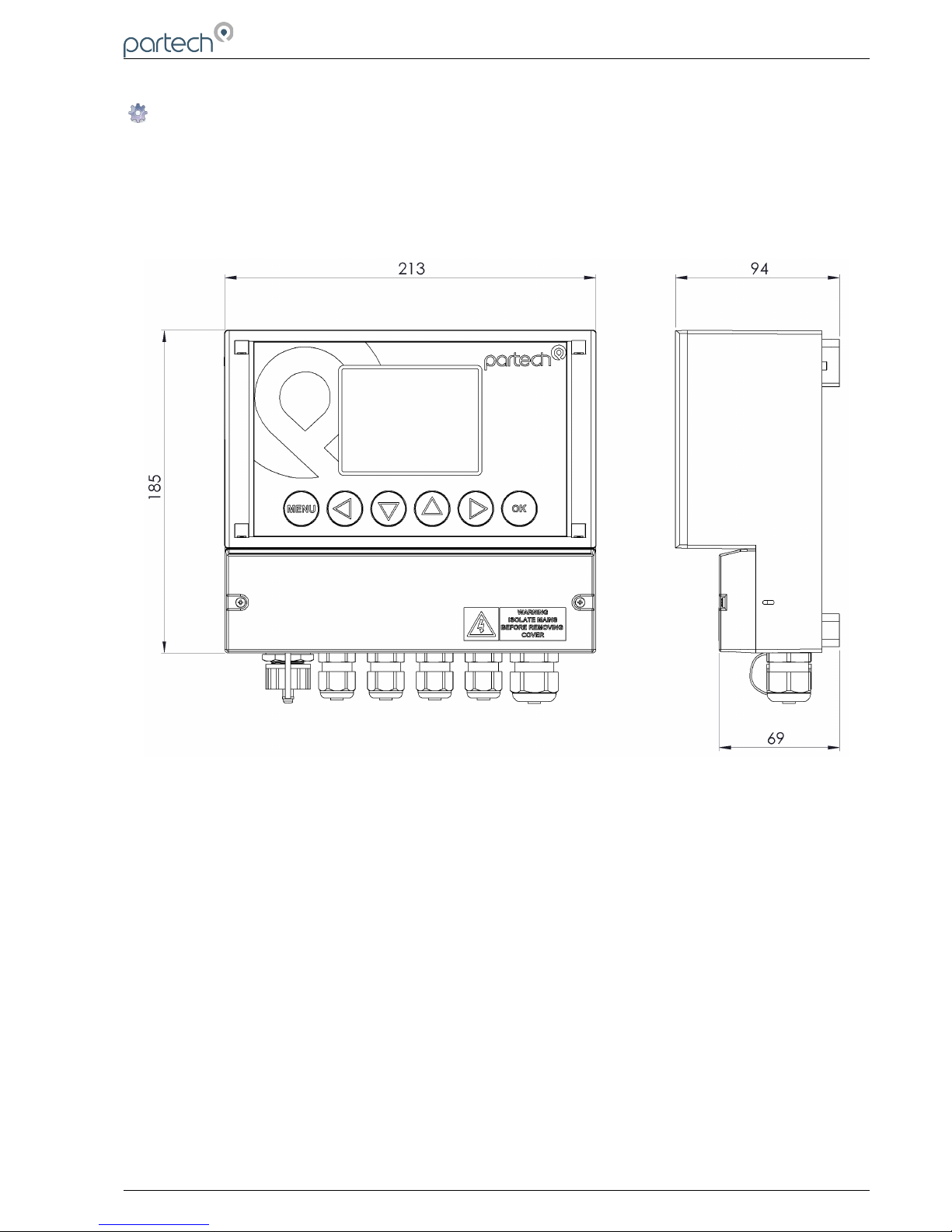
Monitor external dimensions.
4.2 Installation Considerations
Below are a number of points to be considered when deciding on a final location to install or mount the
7300w² Monitor.
• If the monitor requires regular inspection or local reading of measurements, ensure the monitor is
mounted in a position that allows for easy reading. Consider operators of all heights.
• If the sensor is to be calibrated by a single person, consideration should be paid to the proximity of
the monitor to the sensor. Some sensors require constant monitoring or staged inputs during the
calibration process. This could be difficult if the sensor is remote from the monitor.
• Keep the monitor out of direct sunlight. This can make the display difficult to read, and in extreme
conditions could cause the monitor to overheat and fail.
• Keep the monitor away from other heat sources or electronics that may transmit or radiate
electromagnetic influences.
• Keep the monitor away from mains power cables, variable speed drives and motor controllers.
• The monitor is suitable for the most demanding of environments. Where there is a likelihood of
physical damage, salt-water spray or cleaning by high pressure hoses, we advise the monitor is
installed inside an enclosure for added protection.
224081IM Issue 22 Issue Date 27/03/2018 ` Page 9 of 46
Page 10
7300w² Monitor Instruction Manual
4.3 Fixings
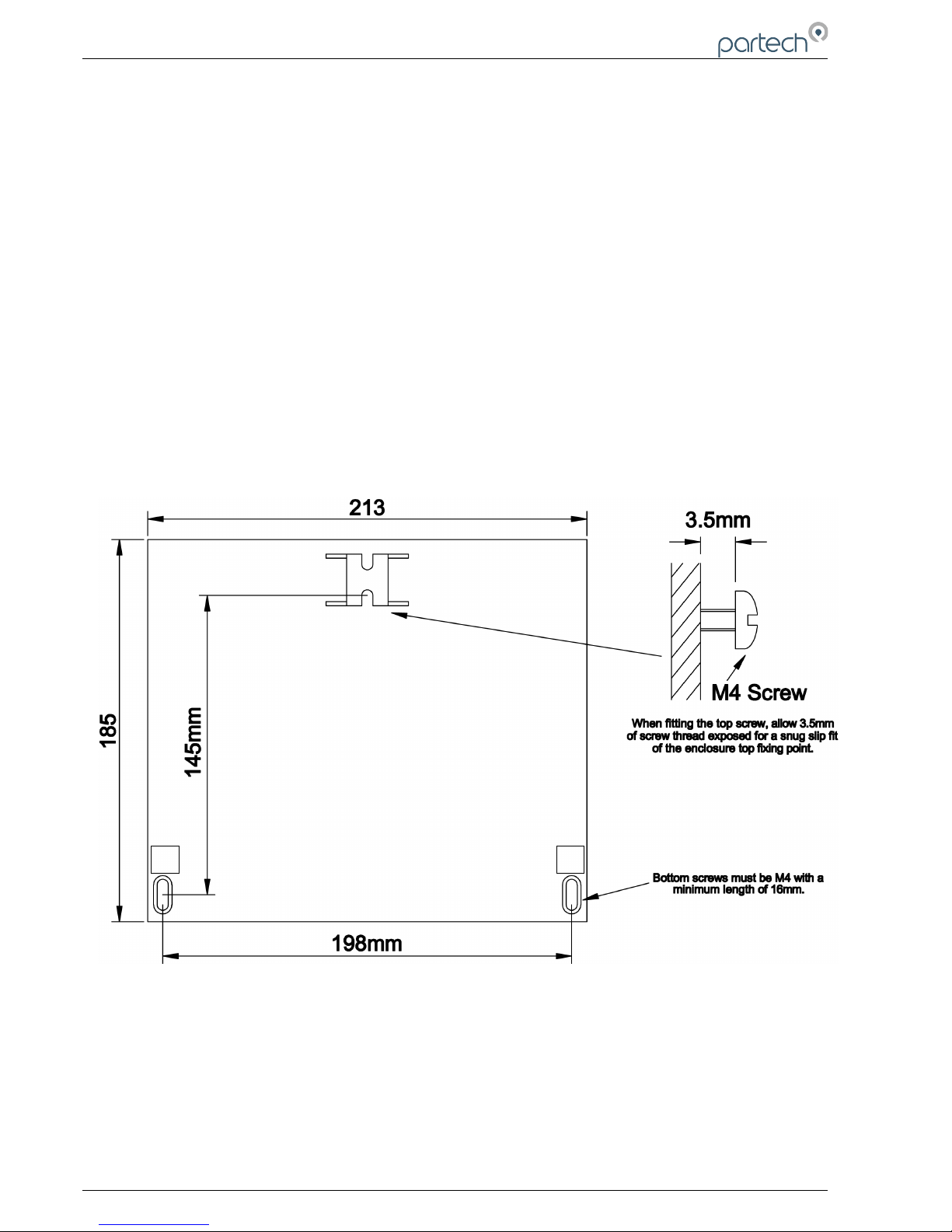
The 7300w² Monitor has 3 fixing points for mounting. Follow these instructions for easy installation and
mounting.
• Offer the monitor up to the final mounting position. Mark the wall behind with a dot halfway along the
top of the enclosure.
• Measure down from the dot 27mm and fit an M4 screw. Ensure the screw has 3.5mm of thread
exposed for a snug fit.
• Hang the enclosure on the screw using the hanging bracket moulded into the back of the monitor
(Loosen the screw if too tight to hang).
• Remove the lower terminal strip cover to reveal the two lower fixing slots (shown as A on the
illustration below).
• Level the Monitor with a spirit level and mark the two lower slots.
• Remove the enclosure and fix drill/tap the above marks.
• Rehang the enclosure (Tighten the top screw if the enclosure feels loose) and fit the two lower
screws. The enclosure has a 14mm shoulder so fixing screws must be at least 16mm long to
penetrate beyond the back of the enclosure.
• Refit the lower terminal cover.
Page 10 of 46 224081IM Issue 22 Issue Date 27/03/2018
A
A
Page 11
7300w² Monitor Instruction Manual
4.4 Electrical Installation
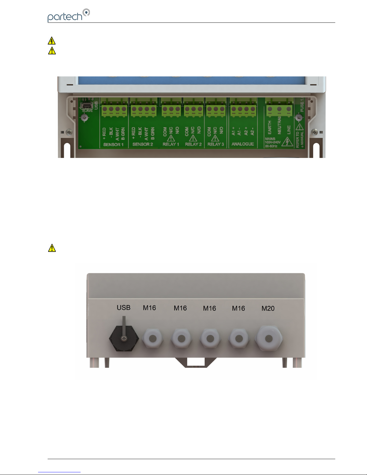
Unscrew the two cover screws on the lower panel of the 7300w² Monitor to reveal the Terminals. Each
terminal strip is labelled as illustrated below. (This equipment must be isolated or disconnected from
HAZARDOUS LIVE voltages before access).
The maximum size wire that can be terminated is 2.5mm² CSA. All the connections are via removable
Plug/Socket terminals. To disengage the terminals, simply pull down to release.
Two power options are available for the 7300w² Monitor, AC and DC. Apart from the supply voltage, all other
connections are identical.
4.4.1 Gland Configuration
The 7300w² Monitor is supplied with IP68 Skintop Nylon glands with lock nuts in the following configuration:
• Left: 1 x USB connection
• Centre 4 x M16 glands (4.5-10mm Ø cable)
• Right: 1 x M20 gland (5-10mm Ø cable)
Gland holes are clearance, not tapped. Always blank unused glands to retain the IP rating of the enclosure
Cabling
When selecting and calculating the mains power cable, please note, an ambient temperature of 60ºC may
see a rise to 80ºC within the terminal compartment. This should be considered when making your
calculations, therefore we recommend a power cable with a maximum rating no less than 80ºC.
Recommended cables include H07RN-F, Steel Wire Armoured or YY, CY or SY types (always check
cable data sheets for maximum temperature ratings, as this can vary between manufactures).
(Refer to BS7671, section 522 “Selection and erection of wiring systems in relation to external
influences” for guidance).
Shrouded Bootlace Ferrules should always be used when terminating conductors.
224081IM Issue 22 Issue Date 27/03/2018 ` Page 11 of 46
Page 12
7300w² Monitor Instruction Manual
4.4.2 DC Power Connections
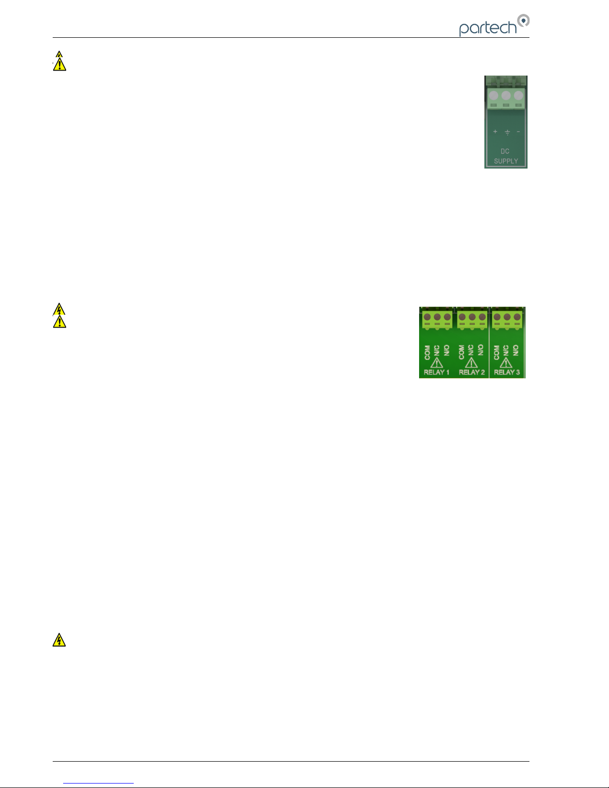
The DC power connection is a 3 way terminal strip, located furthest right of the termination bank.
The left terminal is the Positive (+) supply, the Right terminal is the Negative (-) or Zero voltage
supply and the centre terminal is the Ground.
The power supply is galvanically isolated from all other terminals on the 7300w² Monitor. It is not
necessary to connect a ground to the monitor,.This terminal has been provided for convenience.
The DC powered 7300w² Monitor is powered typically from a 12V to 24V DC supply.
Min/Max Voltages are 9V to 36V. We do not advise operating the monitors in the field at voltages
approaching the Min or Max values as surges, dips or ripples in supply can fall outside the
Max/Min limits and can cause damage or interruptions to the performance of the 7300w² Monitor.
It is recommended that a circuit protective device (5A Trip) or fuse (5A anti-surge fuse) is fitted to the supply
voltage in close proximity to the monitor and located in a position where it is not difficult to operate, replace or
reset the device. The monitor has an on-board 3.5A fuse for internal protection and is fitted with a reverse
polarity diode.
In addition to the protective device, we advise a local isolator or disconnection switch is fitted in close
proximity to the monitor to allow easy disconnection or isolation of the monitor. This switch should be in easy
reach of the operator and clearly marked as the disconnection device for this equipment. This allows for easy
power-down of the monitor during servicing or periods where the monitor is not being used.
NOTE: If the equipment is used in a manner not specified by this manual, the protection provided by the
equipment may be impaired.
4.4.3 AC Power Connections
The AC power terminal strip is a 3 way connector, located furthest right of the
termination bank.
The left terminal is the Earth (E), the Right terminal is the Live supply (L), and the
centre terminal is the Neutral Supply (N).
The AC powered 7300w² Monitor is powered typically from a 100VAC to 240VAC
50/60Hz supply.
Min/Max voltages are 85VAC to 264VAC, 47Hz-63Hz. We do not advise operating the monitors in the field at
voltages approaching the Min or Max values as surges, dips or ripples in supply can fall outside the Max/Min
limits and can cause damage or interruptions to the performance of the 7300w² Monitor.
The supply voltage should be fitted with a 3A Type C MCB (the monitor is prone to inrush currents during
initial power up, therefore a “Motor Rated” Type C MCB should be used to prevent nuisance tripping).
It is recommended that a circuit protective device or MCB is situated in close proximity to the monitor, and
located in a position where it is not difficult to operate or reset the device.
In addition to the protective device, we advise a local isolator or disconnection switch is fitted in close
proximity to the monitor to allow easy disconnection or isolation of the monitor. This switch should be in easy
reach of the operator and clearly marked as the disconnection device for this equipment. This allows for easy
power-down of the monitor during servicing or periods where the monitor is not being used.
The monitor should be adequately earthed. Circuit Protective Conductor (Earth conductor) Cross Sectional
Area (CSA) should not be less than the CSA of the calculated phase conductors.
(Refer to BS7671, section 543 “Protective Conductors” for guidance).
NOTE: If the equipment is used in a manner not specified by this manual, the protection provided by the
equipment may be impaired.
All external wiring should comply with local wiring regulations and standards.
The monitor has an insulation resistance of 3KV, however, care should be taken when conducting insulation
resistance tests. We advise the AC terminal strip is disengaged from the circuit board before such tests are
carried out.
4.4.4 Sensor Connections
When routing the sensor cables, please ensure all cables are separated from any mains cables.
Although the WaterWatch² sensors have a high resistance to interference, separation of mains and
data cables is always good practice and should be followed where practical.
Page 12 of 46 224081IM Issue 22 Issue Date 27/03/2018
Page 13
7300w² Monitor Instruction Manual
All WaterWatch² sensors and Expansion Boxes communicate with the monitor using the ModTechw²
Protocol. This is a modified Modbus Protocol and has been specifically developed to take advantage
of the advanced features and diagnostics designed into the w² range of sensors.
Note: These sensors can NOT be used with other monitors that are not included in the w² family.
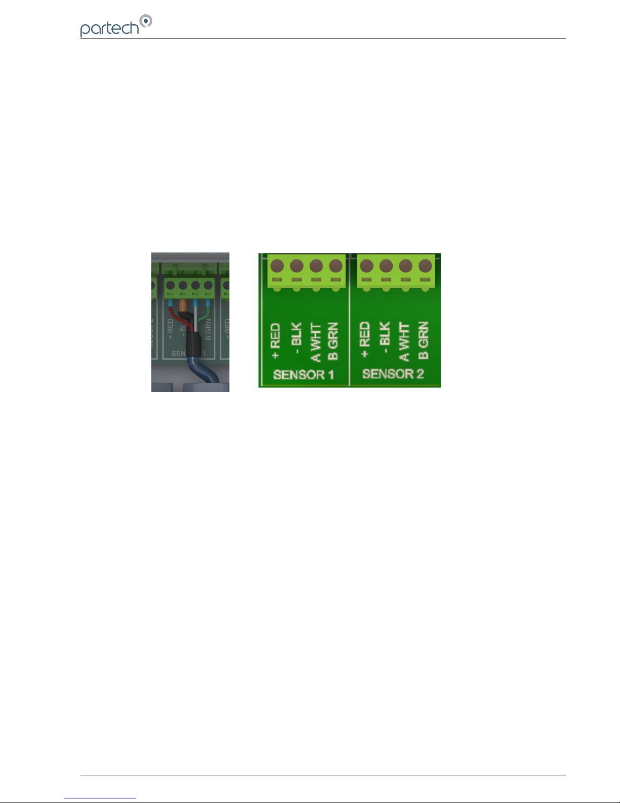
All sensors within the w² family of instruments are connected to the 7300w² Monitor using the same 4 wire
configuration, however some slight variations may occur with specific sensors. Always check the manual
supplied with the sensor to ensure the correct termination is applied.
• RED and BLACK wires provide the 12VDC supply to the sensor and the communication ground.
• WHITE and GREEN provide data communication.
A maximum of two sensors can be directly connected to the standard 7300w² Monitor, however additional
sensors can be added using optional Expansion Boxes available separately.
Remove the 4-way connector from the 7300w² Monitor by pulling downwards to disconnect for easy access
to the connections. Connect the sensor cores as follows:
(Terminals from left to right on the 4 way connector)
Term 1 (Left) - RED (+12V)
Term 2 - Black (0V) and Drain
Term 3 - White (Data A)
Term 4 (Right) - Green (Data B)
Always connect the screen drain wire with the Black (Term 2). Illustration Left shows drain wire and Black
wire connected together, and covered in Black Heat shrink.
Always use Bootlace ferrules when terminating the sensors to ensure a good connection to the terminals.
4.4.5 Extending Sensor Cables
Sensors are usually supplied with 10m cables (longer cables can be provided on request). These cables can
be extended to a maximum length of 100m. To ensure optimum performance, we advise the use of Partech
ModTechw² cable for extensions. Partech can supply Junction Boxes to allow for easy termination of cable
extensions. These should be used on all installations where the cable length from the sensor to the monitor
exceeds 20M (Partech Junction Boxes include on-board filtering for long cable lengths). Junction Boxes are
also useful for local connection of sensors close to the sample point. This permits easier replacement of
sensors without the need to pull back cables to the monitor. The Junction Box has an on-board terminator
switch that can be activated to terminate the network if the sensor is to be removed for long periods.
When joining cables, ensure the connection is fully waterproof. Any moisture ingress can effect the
performance of the sensor and monitor. Always ensure the earth screen is continued when making joints.
ModTechw² Cable specification:
• 2 Twisted Pair: Red/Black (Power) and Green/White (Data) with Screen and Drain wire
• Cores 24AWG (0,22mm²) 7 x 0,20mm
• Outer Insulation: PUR Polyurethane Blue (RAL5003), Diameter – 5mmØ
224081IM Issue 22 Issue Date 27/03/2018 ` Page 13 of 46
Page 14
7300w² Monitor Instruction Manual
4.4.6 Relay Outputs (Alarms)
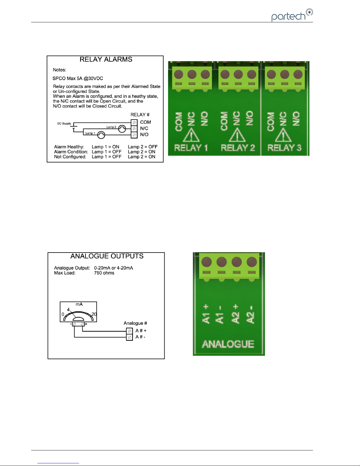
The relay outputs are 3 way terminal strips, located in the middle of the termination bank. The 7300w²
Monitor offers 3 SPCO relay contacts that are user configurable.
Please refer to the “Alarm Configuration” section of this manual for details of how to configure the relays for
alarms or process control outputs.
The relays can switch non-inductive loads up to a maximum of 5A, and withstand voltages up to 240VAC.
Please note, for “Alarm” applications the relays are fail safe. Once configured, the relays will remain
energised in a non-alarmed state (Healthy), therefore N/C will be “Open Circuit”, and N/O will be “Closed
Circuit”. During an Alarm condition, system fault or power failure the relay will de-energise, returning back to
the state illustrated on the label. If the alarm has not been configured, the relay will remain de-energised.
4.4.7 Analogue Outputs
The 7300w² Monitor provides the user with two 0/4-20mA analogue outputs. The Analogue outputs are
connected to the 4 way terminal strip located towards the right of the terminal bank.
Each analogue output can be configured as either 0-20mA or 4-20mA, and can represent any measurement
configured. This configuration set-up is detailed in the “Output Configuration” section in this manual.
The outputs are Active (self-powered loop, does not require external powering) . Each analogue output can
drive a maximum load of 750 ohms.
Expansion Boxes
Page 14 of 46 224081IM Issue 22 Issue Date 27/03/2018
Page 15

7300w² Monitor Instruction Manual
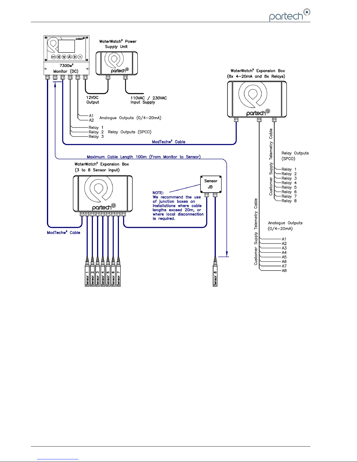
Expansion Boxes are available to increase the number of inputs and outputs for the 7300w² Monitor. These
are available in the following configurations.
PN224920: WaterWatch² Expansion Box (1x 4-20mA Input) – see 6.2.5 for details
PN224468: WaterWatch² Expansion Box (3 to 4 Sensor Input)
PN224473: WaterWatch² Expansion Box (3 to 8 Sensor Input)
PN224476: WaterWatch² Expansion Box (8 x 4-20mA and 8 x Relay Outputs)
PN224939: WaterWatch² Expansion Box (3 to 4 Sensor Input, 4 x 4-20mA and 4 x Relay Outputs)
Each Expansion Box connects to a “SENSOR” terminal of the 7300w² Monitor. Connections into the
Expansion Boxes are the same as for the 7300w², and the same precautions apply.
NOTE: Once the Expansion Boxes have been wired, unplug each 4-way connector from the 7300w²
Monitor before powering up the unit. The system must recognise each box in turn through the
ModTechw² Protocol “Add Expansion Config. Menu”. Similarly disconnect all Sensors from the
Expansion Box before power up, see “Add Sensor Config. Menu”.
When using 8x Sensor Input Expansion Boxes, an additional Power Supply is required to reduce the
risk of overloading the 7300w² Monitor when connecting more than two TurbiTechw² sensors. This
power supply should be rated at 12VDC 2A min, and connects to the “EXT PWR” terminal of the
Expansion Box. A suitable power supply is available from Partech.
See the Data sheet supplied with each expansion box for full configuration details.
224081IM Issue 22 Issue Date 27/03/2018 ` Page 15 of 46
Page 16
7300w² Monitor Instruction Manual
Example of a typical 8x Input and 8x Output Expansion Box installation
Page 16 of 46 224081IM Issue 22 Issue Date 27/03/2018
Page 17
7300w² Monitor Instruction Manual
5 Basic Operation
5.1 Keys and Screen Navigation
All menus and parameter settings are accessed using the 7300w² Monitor membrane keypad.
5.1.1 Menu Button
From the measurement display screen press to show the Main Menu. While in sub menus, acts as a
return to the previous menu.
5.1.2 Navigation Buttons
Use the navigation buttons to move the cursor up, down or across menus. For example, when setting the
“Time” press or to move the cursor over the number to be changed, and press or to change
the number. These buttons can also be used to change the display screen for multi measurement
displays.
5.1.3 OK Button
Press to accept a value or to select a sub menu.
5.2 Default Configuration
When the Monitor is powered up for the first time, the display will show a single measurement that is
DISABLED. This indicates no sensors or measurements have been configured. Each sensor and
measurement must be configured before a value is displayed.
5.2.1 Electrodes, Sensors and Measurements Definition
Throughout the WaterWatch² product range the terms Electrode, Sensors and Measurement will be used in
the following manner:
Electrodes: this applies to the measuring element such as a pH electrode, often the replaceable or
consumable part of a sensor.
Sensors: this term applies to a physical device that is connected to a monitor using a ModTechw²
cable. Sensors may provide one or more measurements.
Measurements: this term applies to the parameters that can be displayed. A single sensor (depending
on type) may provide one or more measurements, e.g. pH and Temperature.
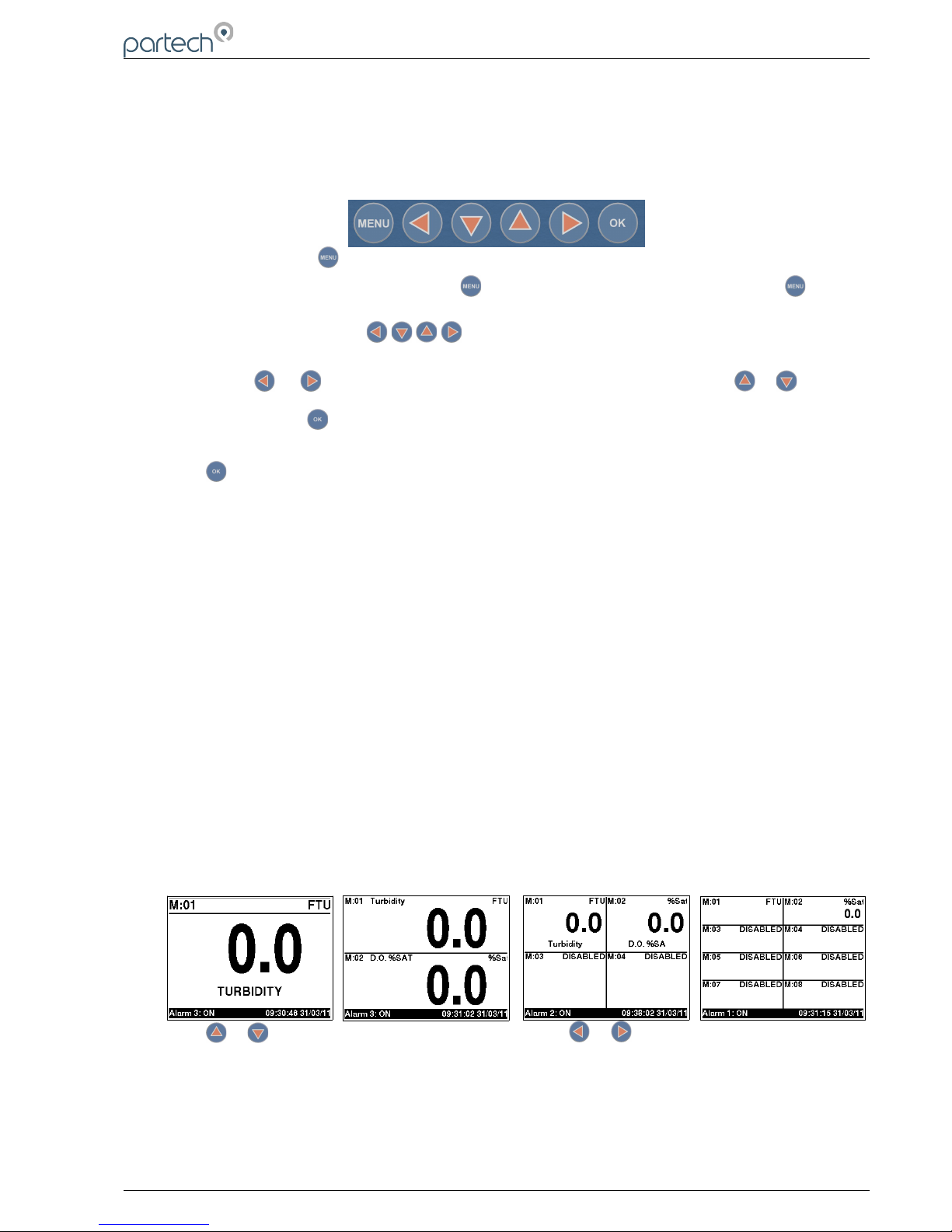
5.3 Measurement Display Mode
The monitor can be configured to display multiple measurements, from 1 to 8 simultaneously (as
shown below). Trend charts can also be displayed for each measurement individually. During a power
disruption, the monitor will default to the last selected display format.
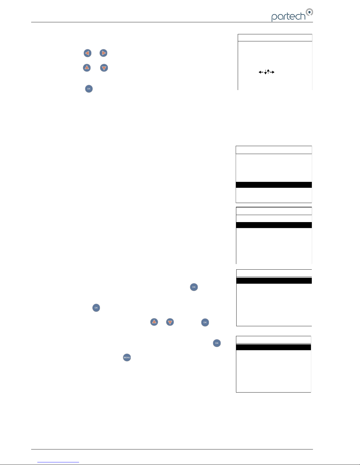
Press or to toggle between the five display modes and or to scroll between Trend
Charts.
224081IM Issue 22 Issue Date 27/03/2018 ` Page 17 of 46
Page 18
7300w² Monitor Instruction Manual
5.3.1 Trending Display Mode
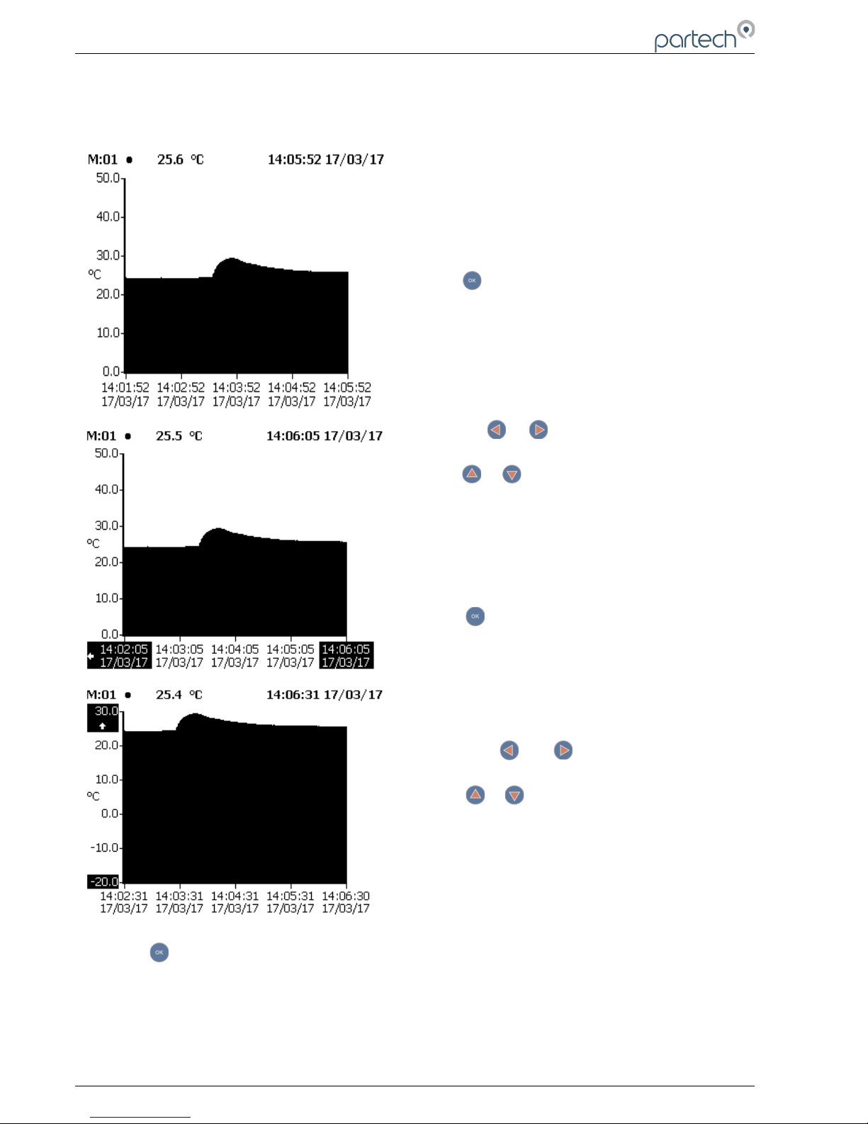
The trending display always the data to be plotted against time. The data goes back 24 hours.
Press to enable scrolling and zooming on the
trending chart.
Press the or to scroll back and forth in time.
Press or to zoom in and out on the time
axis.
Press once again to enable scrolling and
zooming on the measurement axis.
Press the or to zoom out and in on the
measurement axis (respectively)
Press or to move up or down the measurement
axis.
Press to return to the main trending window.
Page 18 of 46 224081IM Issue 22 Issue Date 27/03/2018
Page 19
7300w² Monitor Instruction Manual
6 System Configuration.
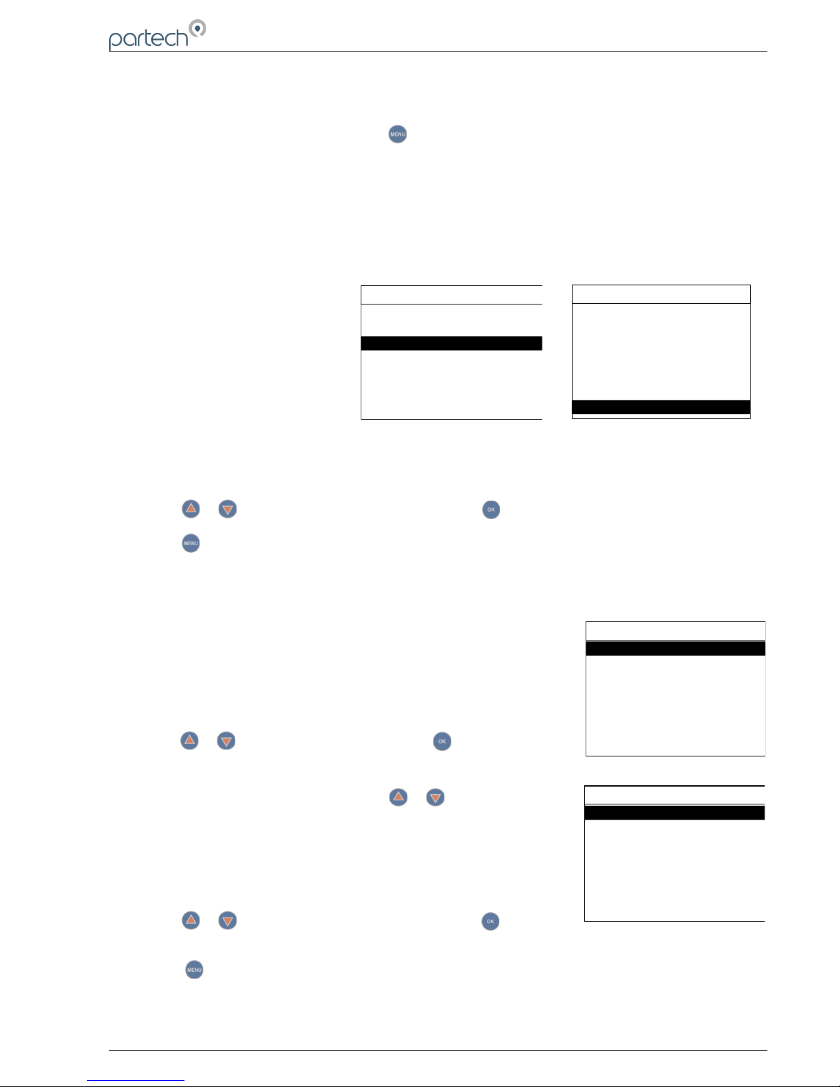
From the Measurement Display press to enter the “MAIN MENU”. From this menu, all
configurations and parameters are defined.
Setting up the monitor is a simple and intuitive process. The menu structure has been designed to lead
the operator through the configuration process. Simply start with the menu at the top and work down
through the menus.
Menu options are:
Monitor Config.
Expansion Config.
Sensor Config.
Measurement Config.
Alarm Config.
Output Config.
Information
Lock Config.
Press or to highlight the menu required, and press to select.
Press at any time to return back to the previous menu.
Note: If no key is pressed for 2 minutes, the monitor will default back to the measurement display
screen.
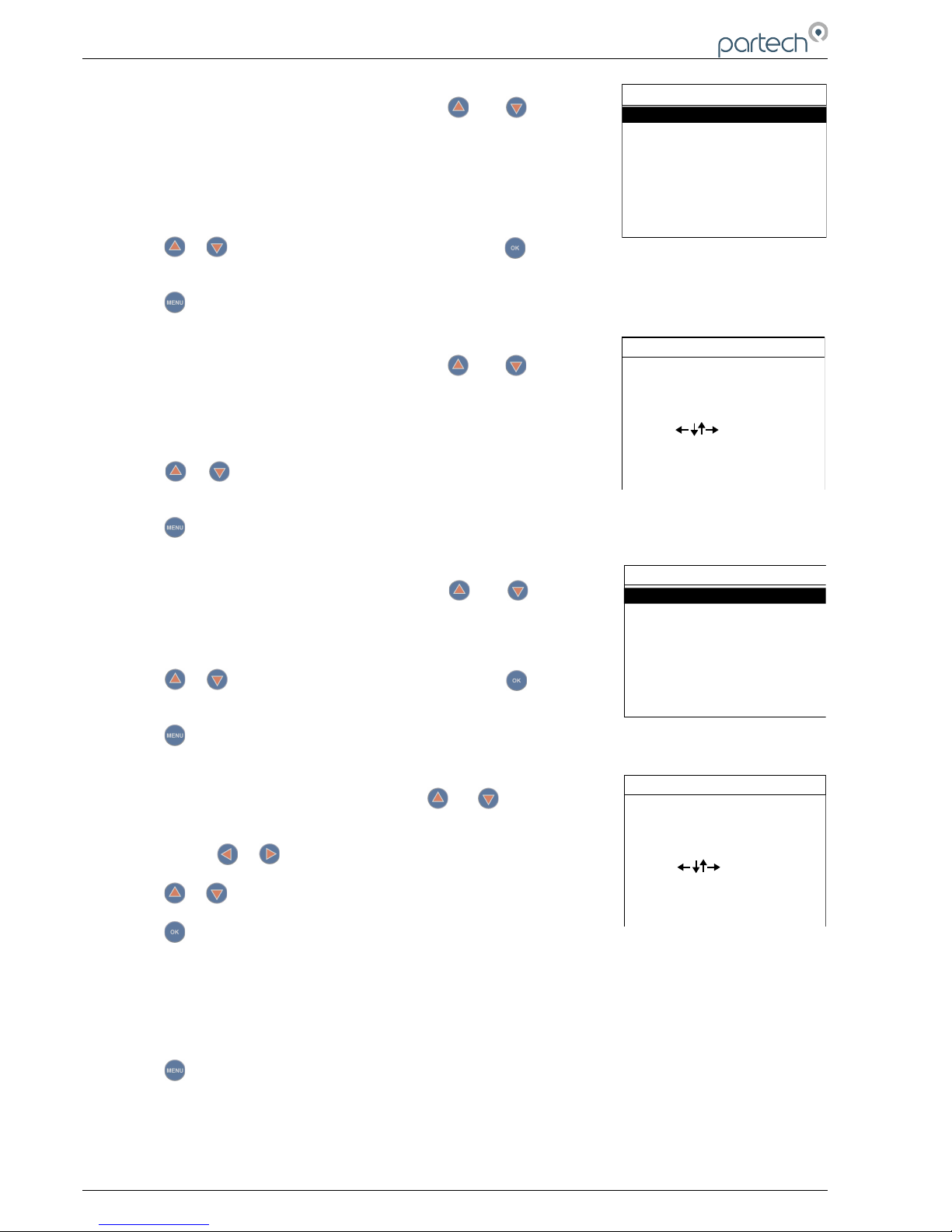
6.1 Monitor Config Menu
The MONITOR CONFIG menu is used to set up the core monitor
functions, including backlight, bleeper function, time and date. This main
menu option also provides access to some advanced configuration and
reset functions.
From the MAIN MENU, ensure MONITOR CONFIG is highlighted (if not,
press or to highlight the option) then press .
6.1.1 Bleeper
From the MONITOR CONFIG menu press or to select BLEEPER.
The bleeper (button pressed acknowledgement bleep) can be turned on
or off as desired. Under normal circumstances it is preferable to leave the
bleeper turned on as it provides an audible feedback of key presses and
a triple bleep is confirmation that a function has been successfully
changed or selected.
Press or to highlight the option required, and press to select. A
tick will appear next to your selection.
Press to exit this option.
224081IM Issue 22 Issue Date 27/03/2018 ` Page 19 of 46
MONITOR CONFIG
Beeper
Backlight
Contrast
Language
Set Date & Time
Enable Service Mode
BEEPER
Off
On ✓
MAIN MENU
Expansion Config
Sensor Config
Measurement Config
Alarm Config
Output Config
Information
Bottom of Main Menu screen with Lock Config
Lock Config
MAIN MENU
Monitor Config
Expansion Config
Sensor Config
Measurement Config
Alarm Config
Output Config
Information
Top seven options of Main Menu
Page 20
7300w² Monitor Instruction Manual
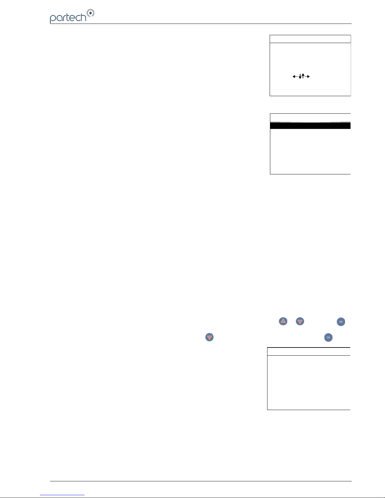
6.1.2 Backlight
From the MONITOR CONFIG menu press or to select
BACKLIGHT.
The backlight can be set to always ON, always OFF or ON after key
press (backlight will switch off again after a period of inactivity). There is
a marginal power saving by having the backlight switched off, otherwise
this setting is down to user preference.
Press or to highlight the option required, and press to select. A
tick will appear next to your selection.
Press to exit this option.
6.1.3 Contrast
From the MONITOR CONFIG menu press or to select
CONTRAST.
The factory setting of 50% should be sufficient for most ambient light
conditions. For different conditions the contrast can be altered.
Press or to increase or decrease the Contrast by 5% (the screen
contrast will react with each press of the buttons).
Press to exit this option.
6.1.4 Language
From the MONITOR CONFIG menu press or to select
LANGUAGE.
The factory default setting is English.
Press or to highlight the option required, and press to select. A
tick will appear next to your selection.
Press to exit this option.
6.1.5 Set Time/Date
From the MONITOR CONFIG menu press or to select SET
TIME/DATE.
1. Press or to move the cursor below the digit to be changed.
Press or to increase or decrease the digit.
Press to accept.
Daylight Savings: The monitor does not automatically update the time to take into account “Daylight
Savings”, as this can cause confusion when data logging. Daylight saving will show a one hour gap
when the clocks go forward and duplicate time stamps when the clock goes back. It is therefore
recommended that the monitor is set to GMT or the time base for the installed location (i.e. GMT+
00:00 for the UK).
Press to exit this option.
Page 20 of 46 224081IM Issue 22 Issue Date 27/03/2018
BACKLIGHT
Always Off
Always On ✓
On after keypress
CONTRAST
50%
Use to set value
Press OK to accept
Press MENU to cancel
LANGUAGE
English ✓
Danish
Dutch
French
Norwegian
Turkish
SET DATE & TIME
09:47:58 25/07/2014
Use to set value
Press OK to accept
Press MENU to cancel
Page 21
7300w² Monitor Instruction Manual
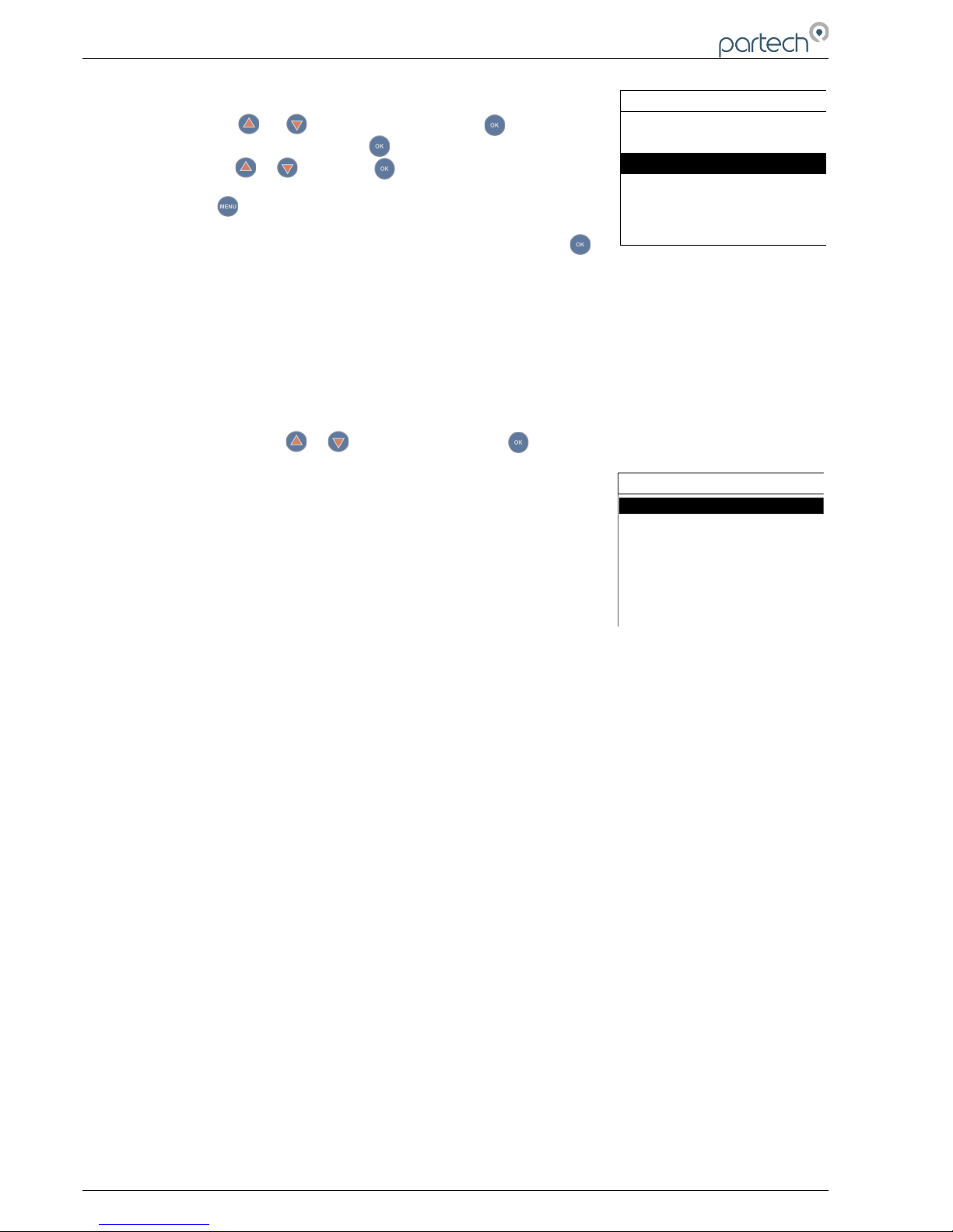
6.1.6 Enable Service Mode
Service mode allows the user access to diagnostic information and
detailed set-up parameters. This will normally be used under the guidance
of a Partech engineer, see section 7.
6.2 Expansion Config
6.2.1 Expansion Status
This option will show the relevant information associated with any
expansion box attached to the Monitor: Serial Number, Modbus Address
etc. Details are for information only and are not editable.
Information about an Input Only Expansion Box will not be displayed in
“Expansion Status” as this is just a physical expansion of a Modbus wiring
network. Adding Sensors to this box will be found by the ModTechw²
Protocol in the Sensor Config Menu.
This applies to the following part numbers:
PN224468: WaterWatch² Expansion Box (3 to 4 Sensor Input)
PN224473: WaterWatch² Expansion Box (3 to 8 Sensor Input)
6.2.2 Add Expansion
This applies to the following part numbers:
PN224476: WaterWatch² Expansion Box (8 x 4-20mA and 8 x Relay Outputs)
PN224939: WaterWatch² Expansion Box (3 to 4 Sensor Input, 4 x 4-20mA and 4 x Relay Outputs)
These boxes must be installed and configured individually before use. The configuration only applies
to the Output and Alarm features, the sensors will be found by the ModTechw² Protocol in the Sensor
Config Menu.
1. After power up plug in the first expansion box.
2. From the MAIN MENU screen, select EXPANSION CONFIG by pressing or , and press .
3. The EXPANSION MENU is displayed. Press to highlight ADD EXPANSION, and press .
4. The Monitor will now search by the ModTechw² Protocol all
possible addresses (0 to 240) to find any attached Expansion
Box.
5. Once the search is complete, the Monitor will display the box just
found.
6. Expansion Box addition is now complete and ready to be
configured.
If additional Expansion Boxes of the same type are to be added, it will be necessary to change the
Modbus address of the installed box. This must be done before any sensors or another box is
plugged in. See 6.2.5 for a full explanation and 6.3.6 for the default Modbus Address table.
224081IM Issue 22 Issue Date 27/03/2018 ` Page 21 of 46
ENABLE SERVICE MODE
Enter Service Password
00000
Use to set value
Press OK to accept
Press MENU to cancel
EXPANSION CONFIG
Add Expansion
<No Expansion Installed>
Expansion Status
ADD EXPANSION
Checking 012
Press MENU or OK to exit
Page 22
7300w² Monitor Instruction Manual
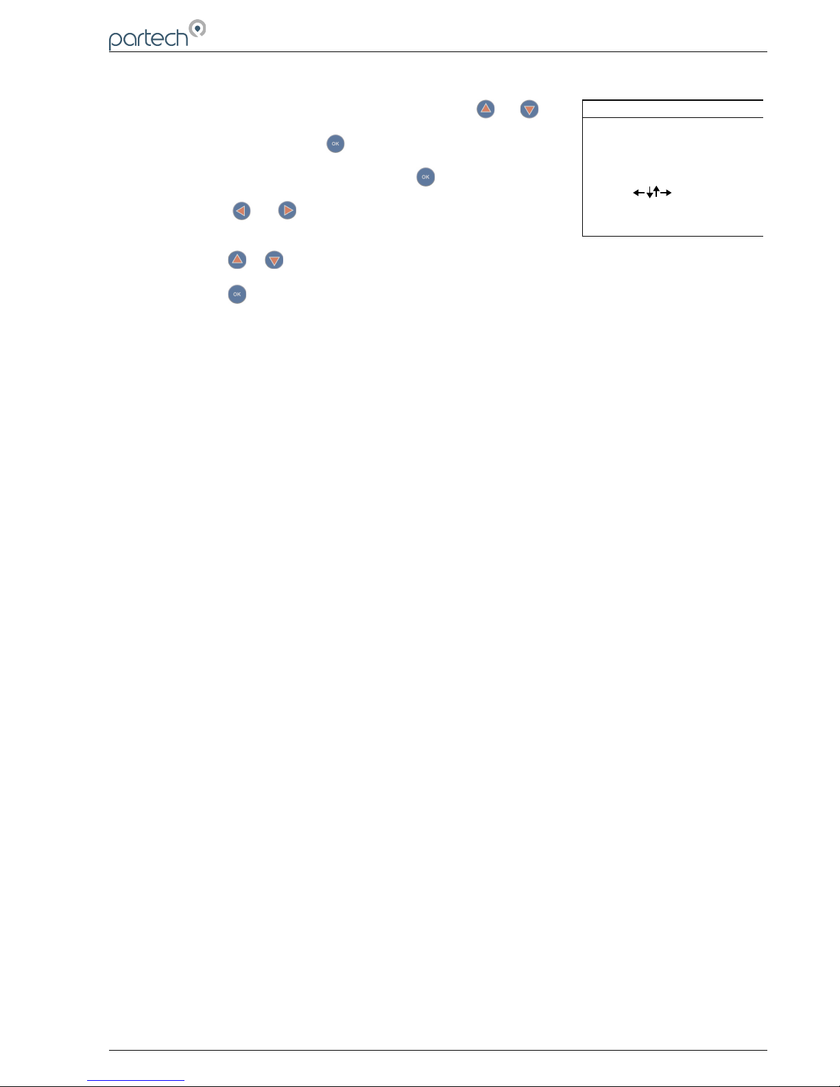
7. From the Expansion CONFIG screen, select the required
Expansion Box to be configured, e.g. “E:1 WW² EB 8A 8R” by
pressing or to highlight, then press . Select “E:0#
Modbus Address” and press . Change the number to 09 by
pressing or then press .
8. Press to return to the Expansion Config Menu.
9. Plug in the next box and select ADD EXPANSION and press .
10. Follow the instructions from 4 to 6. The Modbus address will not need to be changed.
6.2.3 Expansion Box Config Menu
This configuration allows the user to view the Expansion Box Information, option to Delete the box or Change
it's Modbus address. The other features apply commonly to all the Output and Alarm channels where the
settings are used in the event of a communications failure. These options are explained below.
1. From the Expansion CONFIG screen, select the required Expansion Box to be configured, e.g. “E:1 WW²
EB 8A 8R” by pressing or to highlight, then press .
2. Once selected, the CONFIG MENU will be displayed.
• E:0# Info: Displays information relating to the Expansion Box,
including Type, Serial number, Status and Modbus address.
• E:0# Remove: Select this option to remove an Expansion Box
from the monitor.
• E:0# Modbus Address: Use this option to change the Modbus
address of the Expansion Box. This may be necessary if
additional Expansion Boxes are attached. See 6.2.4.
• E:0# Comm Fail Timeout: Default setting – 5 seconds. If there is a failure in communication with the
monitor for the duration of 5 seconds, the analogue outputs and relays will default to their configured
“OUTPUT COMM FAIL” and “RELAY COMM FAIL” states as explained in the relevant Output and
Alarm sections.
• E:0# Output Comm Fail: This is the default condition the analogue outputs will be forced to in the
event of a communication error with the monitor. Condition options include 0mA, 4mA, 20mA or Hold
last good value.
• E:0# Relay Comm Fail: This is the default condition the relay outputs will be forced to in the event of
a communication error with the monitor. Condition options include Off (de-energised), On
(Energised) or Hold last good condition.
Where # represents the Expansion Box number as more than one Expansion Box can be configured.
6.2.4 Changing Expansion Modbus Address
All WaterWatch² Sensors and Expansion Boxes communicate with the monitor using the ModTechw²
Protocol. This protocol is a modified Modbus Protocol, and has been specifically developed to take
advantage of the advanced features and diagnostics designed into the w² range of sensors. The term
“Modbus Address” has been used as a generic term to describe the address of each Sensor and Expansion
Box on the ModTechw² network.
When configuring two or more of the same Expansion Boxes to a monitor, it is necessary to change
the address of the first Expansion Box before installing the next.
All sensors and Expansion Boxes have default addresses starting from address 10 to 240, leaving
addresses 1-9 free for user configuration. It is good practice to allocate Sensors 1-8 to Modbus
Address 1–8 and the first Expansion Box to Modbus Address 9.
Page 22 of 46 224081IM Issue 22 Issue Date 27/03/2018
EXPANSION CONFIG
Expansion Status
Add Expansion
E:1 WW² EB 8A 8R
E:1 CONFIG
E:1 Modbus Address
E:1 Modbus Stats
E:1 Comm Fail Timeout
E:1 Output Comm Fail
E:1 Relay Comm Fail
E:1 Info
Page 23
7300w² Monitor Instruction Manual
Modbus address of the Expansion Box is changed as follows:
1. From the EXPANSION CONFIG screen, use or to
highlight the Expansion Box to be re-addressed i.e. “E:1 WW²
EB 8A 8R”, then press to select.
2. Select MODBUS ADDRESS and press to select.
3. Press or to move the cursor below the digit to be
changed.
4. Press or to increase or decrease the digit.
5. Press to accept.
Once the Modbus address has been changed, you are then free to plug in and configure the next
Expansion Box. Note: The Modbus address is stored in the Expansion Box and not in the 7300w²
Monitor.
6.2.5 Expansion Box PN224920 – Single Analogue Input
The single 4-20 mA input expansion box is treated slightly differently to the other expansion boxes as it
needs configuration that is similar to a sensor.
Therefore to add this box to the 7300w² Monitor go to the Sensor Config menu and select 'Add
Sensor'.
The monitor will scan the Modbus addresses and will find PN224920 at Modbus address 39. If multiple
boxes of the same type are to be added then please change the Modbus address to a free number as
explained in other parts of this manual.
As part of the sensor addition a default measurement will be added, this can be configured as follows:
• Title – select from the list, or create a 'User Defined' title
• Units – select from the list, or create a 'User Defined' title
• Set 4mA/20 mA – this allows you to create an offset at 4mA or 20 mA to cater for inaccuracies in the
sensor being attached to our monitor
• Average – see section 6.3 below
• Display Position – see section 6.3 below
• Remove – see section 6.3 below
224081IM Issue 22 Issue Date 27/03/2018 ` Page 23 of 46
E:01 MODBUS ADDRESS
10
Use to set value
Press OK to accept
Press MENU to cancel
Page 24
7300w² Monitor Instruction Manual
6.3 Sensor Config
The monitor leaves the factory with no sensors pre-installed. Before attempting to configure a
measurement, the sensor must be installed. At this stage it is worth reviewing the contents of the
sensor manual(s) to ensure each sensor has been mechanically and electrically installed correctly.
NOTE: Once the Sensors have been wired, unplug each 4-way connector from the 7300w² Monitor or
Expansion Box before powering up the unit. The system must recognise each sensor in turn through
the ModTechw² Protocol in the “Add Sensor Config Menu”.
Each sensor type in the WaterWatch² range has a unique Modbus address number. When connecting
two or more sensors of the same type to a 7300w² monitor, their default Modbus address will conflict
and a communication error will occur. It is therefore necessary to only connect one sensor at a time.
Once the first sensor has been configured, the Modbus address must then be changed before
connecting and configuring the second sensor and so on. This is generally not necessary for sensors
of different types. See 6.3.5.
For further information on the configuration and operation of our sensors
please refer to their relevant manuals supplied with the sensor, please
read both manuals to ensure correct set up and operation. To access
the Sensor Config Menu:
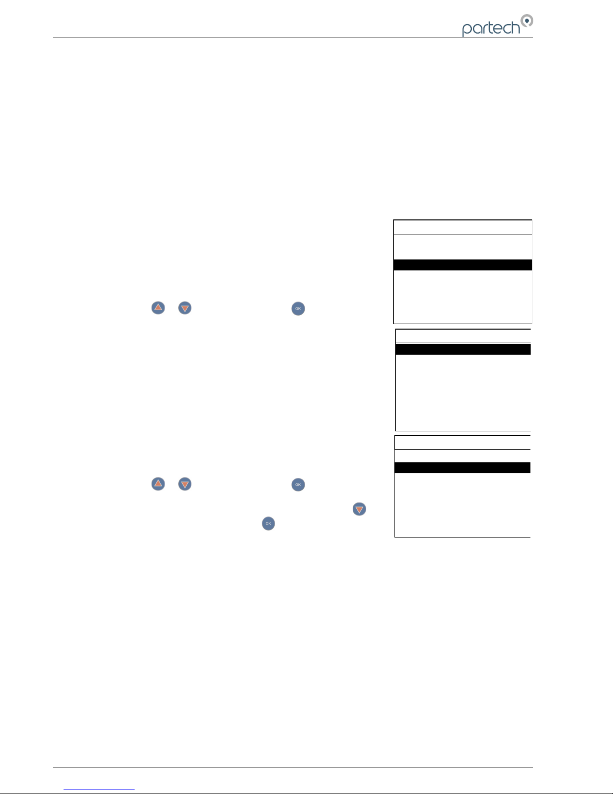
1. From the MAIN MENU screen, select SENSOR CONFIG by
pressing or to highlight, and press .
2. The SENSOR MENU should be displayed.
6.3.1 Sensor Status
This menu will display a list of sensors installed and will include the
serial number for reference. Up to 8 sensors can be configured to a
single monitor. If only one sensor is installed, the remaining seven
sensor allocations will display “Disabled”.
6.3.2 Add Sensor
1. After power up plug in the first Sensor.
2. From the MAIN MENU screen, select SENSOR CONFIG by
pressing or to highlight, and press .
3. The SENSOR MENU should be displayed. Press to
highlight ADD SENSOR, and press .
4. The Monitor will now search by the ModTechw² Protocol all possible addresses (0 to 240) to find any
connected sensors. During the search, any sensors found will be displayed momentarily before
continuing with the search.
5. Once the search is complete, the Monitor will display a list of sensors found. Each sensor will be
automatically allocated a reference from S:01 to S:08.
6. Repeat the above process to install a second, third or more sensors. A total of 8 sensors can be
configured. If sensors of the same type are to be installed, the Modbus address for the first sensor of
that type must be changed before installing the next sensor, See 6.3.5.
7. Sensor addition is now complete.
6.3.3 Sensor Config
Once a sensor has been registered, the monitor will display a list of configurable parameters specific to the
installed sensor. Please refer to the user manual that was supplied with the sensors for full details.
Page 24 of 46 224081IM Issue 22 Issue Date 27/03/2018
SENSOR CONFIG
Sensor Status
Add Sensor
SENSOR CONFIG
Sensor Status
Add Sensor
MAIN MENU
Monitor Config
Expansion Config
Sensor Config
Measurement Config
Alarm Config
Output Config
Information
Page 25
7300w² Monitor Instruction Manual
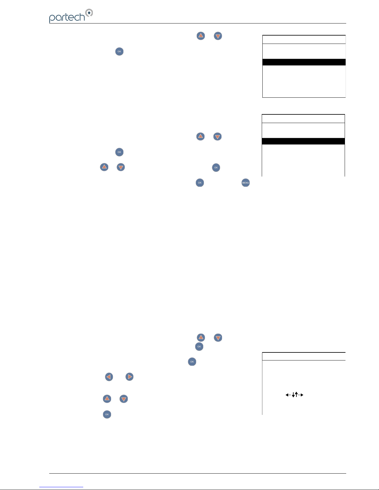
1. From the SENSOR CONFIG screen, use or to highlight
the sensor to be configured: e.g. “S:01 TurbiTechw² LR (0-30)” ,
then press to select.
2. Once selected, the CONFIG MENU will be displayed with
specific parameters available for the sensor.
Please refer to the relevant sensor manual for full configuration details of
the parameters available under this menu.
6.3.4 Sensor Removal
If a sensor is no longer required, the sensor configuration can be
removed from the 7300w² monitor in the following way:
1. From the SENSOR CONFIG screen, use or to highlight
the sensor to be removed; i.e. “S:01 TurbiTechw² LR (0-30)”,
then press to select.
2. Use or to highlight REMOVE and press .
3. Screen will display “Are you sure?”. Press to remove or to exit without removing.
Once removed, any Measurement, Alarms or Analogue outputs configured to the measurement will
also be removed.
6.3.5 Changing Sensor Modbus Address
All WaterWatch² Sensors and Expansion Boxes communicate with the monitor using the ModTechw²
Protocol. This protocol is a modified Modbus Protocol, and has been specifically developed to take
advantage of the advanced features and diagnostics designed into the w² range of sensors. The term
“Modbus Address” has been used as a generic term to describe the address of each sensor and Expansion
Box on the ModTechw² network.
If two or more sensors of the same type are to be installed then once the first sensor has been
configured, it will be necessary to change it's Modbus Address before connecting a second sensor. If
only one sensor is to be connected to the 7300w² monitor or several sensors of different types, it is not
necessary to change the Modbus Address.
All sensors and Expansion Boxes have default addresses starting from address 10 to 240, leaving
addresses 1-9 free for user configuration. It is good practice to allocate Sensors 1-8 to Modbus
Address 1–8.
The following describes how to change the Modbus address of a sensor:
1. From the SENSOR CONFIG screen, use or to highlight the sensor to be re-addressed i.e.
“S:01 TurbiTechw² LR (0-30)”, then press to select.
2. Select MODBUS ADDRESS and press to select.
3. Press or to move the cursor below the digit to be
changed.
4. Press or to increase or decrease the digit.
5. Press to accept.
Once the Modbus address has been changed, you are then free to configure the next sensor.
Note: The Modbus address is stored in the sensor not the monitor.
224081IM Issue 22 Issue Date 27/03/2018 ` Page 25 of 46
SENSOR CONFIG
Sensor Status
Add Sensor
S:01 TurbiTech² LR (0-30)
S:01 MODBUS ADDRESS
18
Use to set value
Press OK to accept
Press MENU to cancel
S:01 CONFIG
S:01 Remove
S:01 Modbus Address
S:01 Info
S:01 Manual Clean
S:01 Clean Config
Page 26
7300w² Monitor Instruction Manual
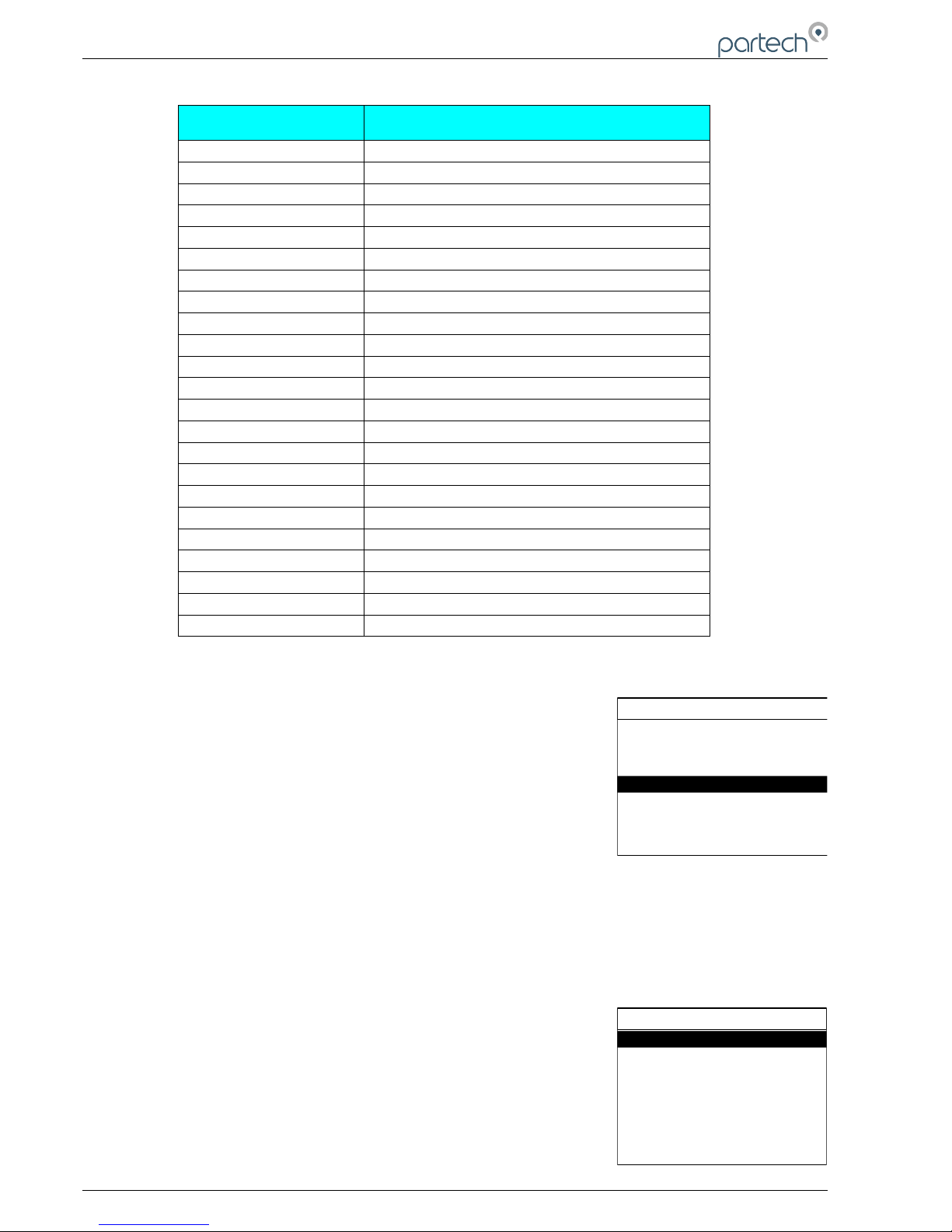
6.3.6 Default Modbus Addresses
Default Modbus
Address
Sensor / Expansion Box
0 Reserved for system – DO NOT USE
1 to 8 User Defined (advise: use for sensors)
9 User Defined (advise: use for Expansion Box)
10 OxyTechw² OPT
11 TurbiTechw² LS
12 TurbiTechw² LA
13 TurbiTechw² HR
14 TurbiTechw² LR (0-500)
15 TurbiTechw² LR (0-30)
16 OxyTechw² GAL
17 ColTechw² (0-200)
18 WaterTechw² pH8000
19 WaterTechw² Redox8000
20 WaterTechw² pHEVT
21 Expansion Box (8x 4-20mA, 8 Relay)
22 Expansion Box (4x 4-20mA, 4 Relay)
23 Expansion Box (4x 4-20mA, 4 Relay, 4 Input)
24 TurbiTechw² LR (0-30)
30 WaterTechw² C4E
33 OilTechw² FLT
37 OxyTechw² RDO Pro
38 OxyTechw² RDO Pro-X
39 Expansion Box (1x 4-20mA)
6.3.7 Measurement Config
The monitor leaves the factory without any configured measurements,
they can only be added after the relevant sensor(s) have been
recognised by the 7300w² Monitor by Sensor Configuration, see 6.3.
The Sensor will upload the available measurement parameters to the
7300w² Monitor and as they are registered the measurements will be
included in a list for the user to configure. A single sensor may only
provide a single measurement (e.g. Turbidity), or multiple measurements
(e.g. DO and Temperature). Each measurement may also be offered in
different formats (e.g. FTU or mg/l for Turbidity). All available
measurements and formats will be displayed under the Measurement Config Menu denoted by M01 to
M0x.
Further information on the configuration, operation and calibration of the measurements supplied by
our sensors are contained in the relevant manuals supplied with the sensor, please read both manuals
to ensure correct set up and operation.
6.3.8 Measurement Status
This option allows the user to review the current status of the 16
measurement channels. Configured measurements will show the type of
measurement and description and serial number of the sensor providing
the measurement. If a sensor is defective the measurement location will
display “S. Disconnected”. If only one measurement is configured, the
remaining fifteen measurement allocations will display “Disabled”.
Page 26 of 46 224081IM Issue 22 Issue Date 27/03/2018
MAIN MENU
Monitor Config
Expansion Config
Sensor Config
Measurement Config
Alarm Config
Output Config
Information
MEASUREMENT CONFIG
Measurement Status
Add Measurement
M:01 TurbiTech² LR NTU (S:01)
Page 27
7300w² Monitor Instruction Manual
6.3.9 Add Measurement
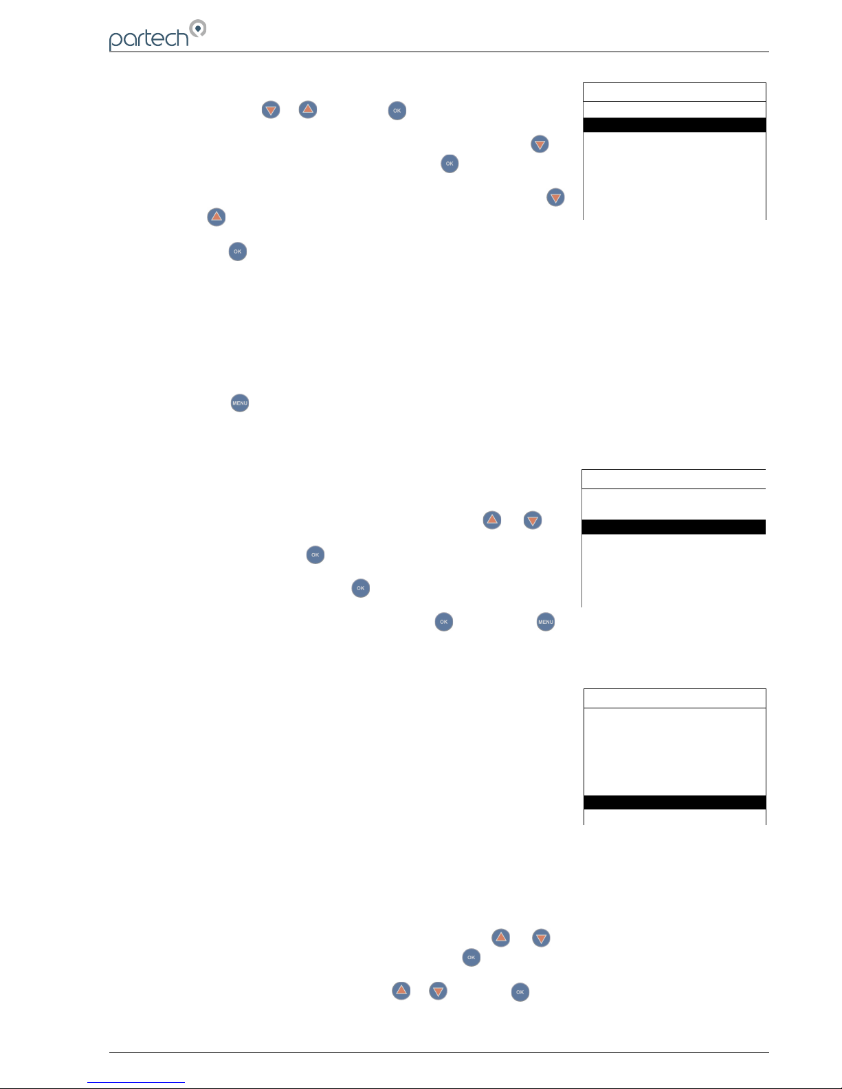
1. From the MAIN MENU screen, select MEASUREMENT CONFIG
by pressing or , and press .
2. The MEASUREMENT MENU should be displayed. Press to
highlight ADD MEASUREMENT, and press .
3. All available measurements will be displayed in a list. Press
or to highlight the first measurement.
4. Press to select the measurement. Repeat the process if more measurements are required.
5. Each measurement will be allocated a measurement number from M:01 – M:16.
e.g. M:01 M.L.S.S. (S:01)
M:03 Dissolved Oxygen (S:04)
N.B. The measurement number has no relevance to the sensor number.
6. Press to return back to the display screen. The first configured measurement should now be
displayed.
6.3.10 Measurement Removal
If a measurement is no longer required, the measurement configuration
can be removed from the 7300w² monitor in the following way.
1. From the MEASURMENT CONFIG screen, use or to
highlight the measurement to be removed i.e. “M:01 Turbidity
(S:01)”, then press to select.
2. Select REMOVE and press to select.
3. Screen will display “Are you sure?”. Press to remove or to exit without removing.
Once removed, any Alarms or Analogue outputs configured to the measurement will also be removed.
6.4 Measurement (Specific) Config
Selecting the measurement in the MEASUREMENT CONFIG menu will
display a new sub-menu associated with that particular parameter. This
will be specific to the measurement of interest. The menu explanation in
this manual is limited only to Display Position. For a full explanation of
this sub-menu see the instruction manual accompanying the sensor.
6.4.1 Display Position
Display Position allows two measurement to swap places, to allow the
user to re-arrange the display as required. The display position refers to the M:0# number allocated to the
measurement. The screen will always display the measurements in order from M:01 to M:16.
To swap measurements, use the DISPLAY POSITION menu.
The example below swaps measurement M:01 with M:03:
1. From the MEASUREMENT CONFIG screen, use or to highlight the measurement to be
moved i.e. “M:01 Turbidity (S:01)”, then press to select.
2. Select DISPLAY POSITION using or and press to select.
224081IM Issue 22 Issue Date 27/03/2018 ` Page 27 of 46
MEASUREMENT CONFIG
Measurement Status
Add Measurement
M:01 TurbiTech² LR NTU (S:01)
MEASUREMENT CONFIG
Measurement Status
Add Measurement
M:01 TurbiTech² LR NTU (S:01)
M:01 CONFIG
M:01 Info
M:03 Set Cal (25.0 ºC)
M:03 Remove
M:03 Display Position
M:03 Restore Defaults
M:03 Remove
M:03 Display Position
M:03 Restore Defaults
Page 28
7300w² Monitor Instruction Manual
3. The current display position will be shown, e.g. 1 for M:01
Turbidity.
4. Press or to move the cursor below the digit to be changed.
5. Press or to increase or decrease the digit to the desired
new position (e.g. 3)
6. Press to accept. Measurement M:01 will now become
Measurement M:03, and the measurement registered as M:03 will now become measurement M:01.
7. Note, any alarms or analogue outputs registered to a specific measurement will also be updated to
the new display position (it is not necessary to re-configure alarms or outputs).
6.5 Alarm Config (Relay outputs)
The 7300w² monitor leaves the factory without any alarms configured. Alarms can only be configured
after installing the relevant sensor(s) and measurement(s). The default
condition is OFF.
Skip this section if you have no requirements for alarm outputs.
The ALARM CONFIG menu defines the functions of the 3 relay outputs
within the 7300w² monitor and any additional relay outputs added using
optional Expansion Boxes. Alarm outputs can only be assigned to
configured measurements (M:01 to M:16).
Alarm relays within the monitor will be shown as “ALARM # (M)”, whereas
# denotes relays 1 to 3 and (M) denotes the monitor.
Alarm relays associated with Expansion Boxes will be shown as “ALARM
# (E:1)”, whereas # denotes relays 1- 8 and (E:1) denotes Expansion Box
1.
Important: Without a measurement allocated to an alarm a limited
selection of options will be displayed in Alarm Config. Once a
measurement has been allocated, then a more complete selection will be
available. (See screenshots left)
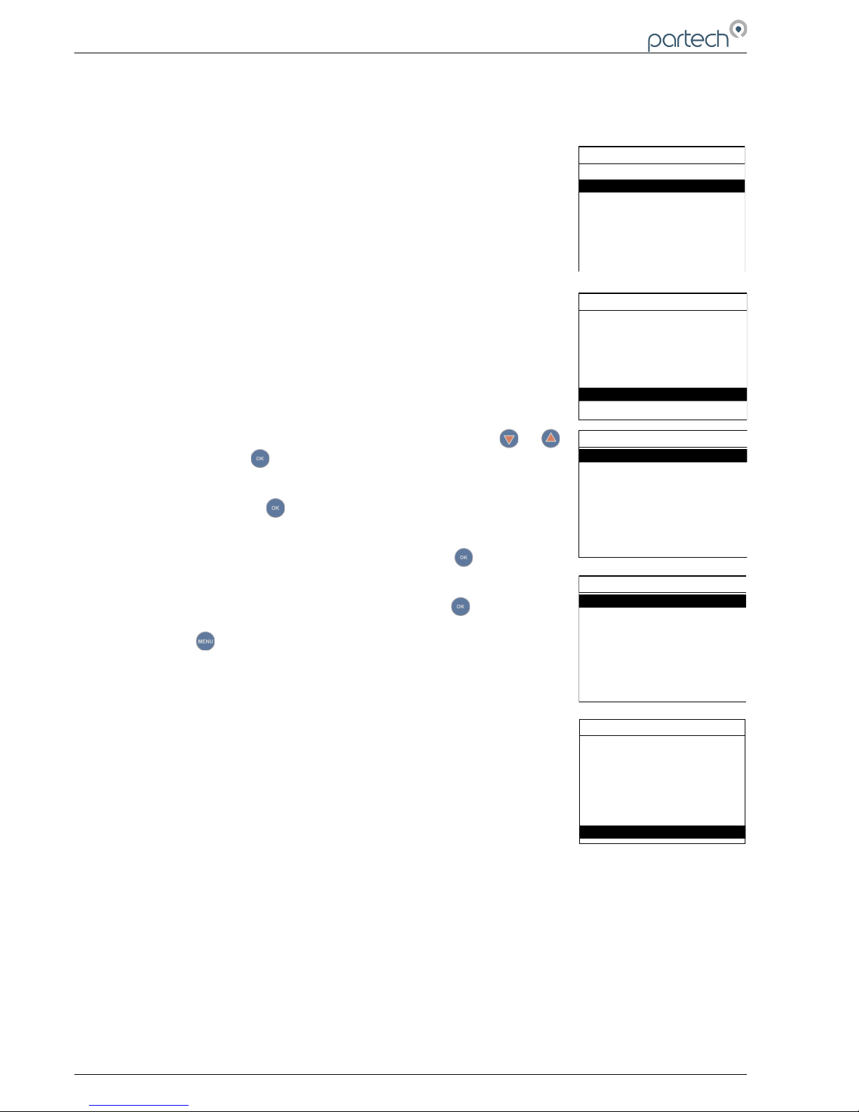
From the MAIN MENU, select ALARM CONFIG and press .
1. Highlight the Alarm output to be configured (e.g ALARM 5 (E:1))
and press .
2. Highlight MEASUREMENT using or and press .
3. A list of your previously configured measurements will be
displayed. Highlight the required measurement and press . A
tick will be displayed next to the measurement showing it has
been selected. Press to return back to ALARM 1 CONFIG
MENU.
4. ALARM 5 CONFIG menu will now display all the options available
to configure the alarm.
5. Listed below are the descriptions of each option. Configure as
required.
• Info: List configuration details for the measurement.
• Measurement: The selected measurement as configured above.
Page 28 of 46 224081IM Issue 22 Issue Date 27/03/2018
M:01 DISPLAY POSITION
1
Use to set value
Press OK to accept
Press MENU to cancel
MAIN MENU
Monitor Config
Expansion Config
Sensor Config
Measurement Config
Alarm Config
Output Config
Information
ALARM CONFIG
Alarm Status
Alarm 1 (M) Config
Alarm 2 (M) Config
Alarm 3 (M) Config
ALARM 1 (M) CONFIG
Alarm 1 (M) Measurement
Alarm 1 (M) Type
Alarm 1 (M) Info
Alarm 1 (M) Value
Alarm 1 (M) Hysterisis
Alarm 1 (M) Fault Setup
Alarm 1 (M) Set Delay
Menu with Measurement Allocated
ALARM 1 (M) CONFIG
Alarm 1 (M) Measurement
Alarm 1 (M) Test
Alarm 1 (M) Info
Alarm 1 (M) Test Cycle
Menu without Measurement Allocated
Page 29

7300w² Monitor Instruction Manual
• Type: Offers the following options:
OFF: No relay output.
LOW: Alarm active on a low reading (below the set point).
HIGH: Alarm active on a high reading (above the
setpoint).
FAULT: Pre-defined System faults.
• Value: The alarm set point, for example, if TYPE has been set to LOW, the alarm will activate at
a measurement equal to or lower than the VALUE, likewise if HIGH is set, the alarm will activate
at a measurement equal to or higher than the VALUE.
• Hysteresis: The value entered for Hysteresis is the dead band where the Alarm will not reset on
a falling value. e.g. A HIGH alarm value of 50mg/l and a Hysteresis of 5mg/l would trigger an
alarm on a rising value of 50mg/l, but will not reset the alarm until the reading falls below 45mg/l.
The opposite is true for a LOW alarm type.
• Fault Setup: If FAULT was selected for TYPE, a list of fault conditions can be selected to
activate the alarm. Highlight the required fault conditions, and press to add or remove a tick.
More than one fault condition can be selected for a single alarm/relay. By default, all faults are
selected.
• Set Delay: The value entered for the Set Delay is used to filter spurious measurements and
spikes from giving a false alarm. e.g. for a HIGH alarm value of 50mg/l and a delay of 10
seconds, the alarm will not activate until the monitor has read a continuous measurement of
50mg/l or higher for more than 10 seconds. If the measurement falls below 50mg/l during the 10
seconds delay the timer will reset.
• Reset Delay: The reset delay is the opposite to the Set Delay, whereas the reading must remain
below the set point value for the duration of the delay before the alarm will reset.
• Test: This menu option is for diagnostics use and allows the operator to test the alarm/relay by
forcing the relay ON/OFF. Press or to switch the relay ON/OFF. Press or to exit.
• Test Cycle: This menu option is for diagnostic use and will cycle the alarm relay ON/OFF every
15 seconds. Press or to exit.
6.5.1 Alarm Addressing with Expansion Boxes
The standard 7300w² Monitor with no Expansion Boxes connected, will only display three alarms in the
“ALARM CONFIG” menu:
Alarm 1 (M) Config = Relay 1 within the monitor
Alarm 2 (M) Config = Relay 2 within the monitor
Alarm 3 (M) Config = Relay 3 within the monitor
When an Expansion Box is connected to the 7300w² Monitor, additional configurable alarms are added
to the list in the “Alarm Config Menu” as follows:
Alarm 1 (E:1) Config = Relay 1 within Expansion Box 1
Alarm 2 (E:1) Config = Relay 2 within Expansion Box 1
Alarm 3 (E:1) Config = Relay 3 within Expansion Box 1
Alarm 4 (E:1) Config = Relay 4 within Expansion Box 1
Alarm 5 (E:1) Config = Relay 5 within Expansion Box 1
Alarm 6 (E:1) Config = Relay 6 within Expansion Box 1
Alarm 7 (E:1) Config = Relay 7 within Expansion Box 1
Alarm 8 (E:1) Config = Relay 8 within Expansion Box 1
224081IM Issue 22 Issue Date 27/03/2018 ` Page 29 of 46
ALARM 1 (M) CONFIG
Alarm 1 (M) Hysterisis
Alarm 1 (M) Fault Setup
Alarm 1 (M) Value
Alarm 1 (M) Set Delay
Alarm 1 (M) Reset Delay
Alarm 1 (M) Test
Alarm 1 (M) Test Cycle
Bottom of Alarm Config Menu
Page 30
7300w² Monitor Instruction Manual
6.6 Output Config (Analogue Outputs)
The 7300w² monitor leaves the factory without any outputs configured. Outputs can only be configured
after installing the relevant sensor(s) and measurements(s). The default condition is OFF.
Skip this section if you have no requirements for analogue outputs.
The OUTPUT CONFIG menu defines the functions of the 2 analogue
outputs within the monitor and any additional analogue outputs added using
optional Expansion Boxes. Analogue outputs can only be assigned to
configured measurements (M:01 to M:16).
Outputs within the monitor will be shown as “OUTPUT # (M)”, whereas #
denotes analogue output 1 or 2 and (M) denotes the monitor.
Outputs associated with Expansion Boxes will be shown as “OUTPUT #
(E:1)”, whereas # denotes analogue outputs 1 to 8 and (E:1) denotes
Expansion Box 1.
Important: Without a measurement allocated to an output a limited selection
of options will be displayed in Alarm Config. Once a measurement has been
allocated, then a more complete selection will be available. (See
screenshots left)
1. From the MAIN MENU, select OUTPUT CONFIG using or
keys and press .
2. Highlight the analogue output to be configured (e.g. OUTPUT 5 (E:1)
Config) and press .
3. The OUTPUT 5 (E:1) Config menu will now be displayed and
OUTPUT 5 (E:1) Measurement highlighted, press .
4. A list of your previously configured measurements will be displayed.
Highlight the required measurement and press . A tick will be
displayed next to the measurement showing it has been selected.
Press to return back to OUTPUT 5 (E:1) Config menu.
5. The OUTPUT 5 (E:1) Config menu will now display all the options
available to configure the output.
6. Listed below are the descriptions of each option. Configure as
required.
• Measurement: The selected measurement as configured
above.
• Type: Offers the following options:
4-20mA: Gives 4-20mA output signal.
0-20mA: Gives 0-20mA output signal.
OFF: Switches off the Analogue signal.
• 4mA or 0mA: The value entered will be the offset value for the analogue output, e.g. a value of
10mg/l for a 4-20mA signal will configure the output to be 4mA at 10mg/l or a value of 2mg/l for a
0-20mA signal will configure the output to be 0mA at 2mg/l. The default value is zero.
• 20mA: The value entered will be the span value for the analogue output, e.g. a value of 50mg/l
for a 4-20mA signal will configure the analogue to be 20mA at 50mg/l.
• Fault Mode: The fault mode will force the analogue signal to a default state if a fault occurs.
Page 30 of 46 224081IM Issue 22 Issue Date 27/03/2018
MAIN MENU
Monitor Config
Expansion Config
Sensor Config
Measurement Config
Alarm Config
Output Config
Information
OUTPUT CONFIG
Output 1 (M) Config
Output 2 (M) Config
Output Status
OUTPUT 1 (M) CONFIG
Output 1 (M) Measurement
Output 1 (M) Type
Output 1 (M) Info
Output 1 (M) 4mA
Menu with Measurement Allocated
Output 1 (M) 20mA
Output 1 (M) Fault Mode
Output 1 (M) Fault Setup
OUTPUT 1 (M) CONFIG
Output 1 (M) Type
Output 1 (M) 4mA
Bottom of Output Config Menu
Output 1 (M) 20mA
Output 1 (M) Fault Mode
Output 1 (M) Fault Setup
Output 1 (M) Test
Output 1 (M) Test Cycle
OUTPUT 1 (M) CONFIG
Output 1 (M) Measurement
Output 1 (M) Test
Output 1 (M) Info
Output 1 (M) Test Cycle
Menu without Measurement Allocated
Page 31

7300w² Monitor Instruction Manual
HOLD will hold the last good measurement if a fault occurs.
LOW will force a 4mA or 0mA output if a fault occurs.
HIGH will force a 20mA output if a fault occurs.
• Fault Setup: A list of possible fault conditions are displayed. If any of these Fault conditions are
detected, the analogue output will default to the setting selected in FAULT MODE. Use or
to highlight the fault condition required, and press to add or remove a tick. More than one
fault may be selected for an output.
• Test: This menu is for diagnostic use and allows the operator to test the analogue by forcing an
output. Press or to increase or decrease the analogue output by 0.5mA for each press.
Press or to exit.
• Test Cycle: This menu is for diagnostic use and will increase the analogue by 0.5mA every 5
seconds. Once the cycle reaches 20mA it will return back to 4mA and continue to increase
again. Used for testing and fault diagnostics. Press or to exit.
• 0/4mA and 20mA Offset: Only displayed under Service Mode, the analogue outputs may be
adjusted to compensate for site conditions. See 7.1.3.
6.6.1 Output Addressing with Expansion Boxes
The standard 7300w² monitor with no Expansion Boxes connected, will only display two analogue outputs in
the “OUTPUT CONFIG” menu:
Output 1 (M) Config = Analogue output 1 within the monitor
Output 2 (M) Config = Analogue output 2 within the monitor
When an Expansion Box is connected to the 7300w² Monitor, additional configurable analogue outputs
are added to the list in the “Output Config Menu” as follows:
Output 1 (E:1) Config = Analogue output 1 within Expansion Box 1
Output 2 (E:1) Config = Analogue output 2 within Expansion Box 1
Output 3 (E:1) Config = Analogue output 3 within Expansion Box 1
Output 4 (E:1) Config = Analogue output 4 within Expansion Box 1
Output 5 (E:1) Config = Analogue output 5 within Expansion Box 1
Output 6 (E:1) Config = Analogue output 6 within Expansion Box 1
Output 7 (E:1) Config = Analogue output 7 within Expansion Box 1
Output 8 (E:1) Config = Analogue output 8 within Expansion Box 1
6.7 Information
This section provides basic information about the equipment that you have
purchased and contact details for Partech.
From the MAIN MENU, ensure INFORMATION is highlighted (if not, press
or to highlight the option) then press .
6.7.1 Software Version
This function displays the installed software (firmware) version and the
monitor serial number. Please have this information available if you need to
contact Partech about this product.
6.7.2 Contact Information
This displays Partech's address, phone number and website URL.
224081IM Issue 22 Issue Date 27/03/2018 ` Page 31 of 46
MAIN MENU
Monitor Config
Expansion Config
Sensor Config
Measurement Config
Alarm Config
Output Config
Information
INFORMATION
Software Version
Contact Information
Page 32
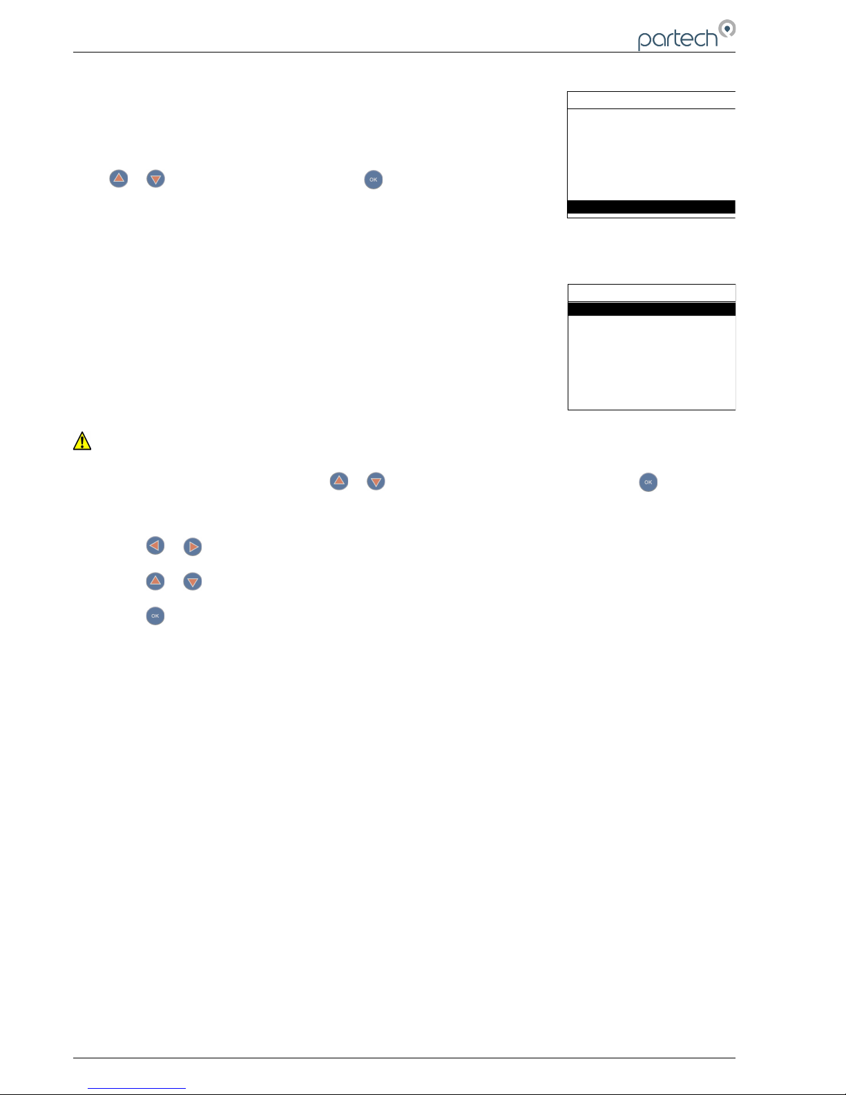
7300w² Monitor Instruction Manual
6.8 Lock Config
This function allows the user to restrict access to all configuration features of
the monitor. This is useful in circumstances where unintended adjustment
may occur.
From the MAIN MENU, ensure LOCK CONFIG is highlighted (if not, press
or to highlight the option) then press .
The keypads will allow access to top level functions such as INFORMATION
and certain features such as BACKLIGHT but will not allow adjustment of any setting that effects the
measurements being made. Users will also be able to use the arrow keys to scroll through the different
display types.
6.8.1 Lock Monitor
Select LOCK MONITOR to lock. You will be prompted for a password. The
factory default password is 1000.
Once entered, the monitor is locked.
6.8.2 Change Password
The CHANGE PASSWORD menu allows the operator to set a user defined
password for menu access.
Care should be taken when changing the password. If the password is lost, it may be necessary for
Partech to visit the instrument to unlock the monitor and reset the password.
From the LOCK CONFIG menu press or to select CHANGE PASSWORD and press .
This screen requests the OLD password. The factory default setting is 1000.
Press or to move the cursor below the digit to be changed.
Press or to increase or decrease the digit.
Press to accept.
You will then be asked to enter the new Password. Repeat the above procedure to set the new
password.
Password is now set.
6.8.3 Set Auto Lock
Two modes of “Lock Instrument” are available and are configured from this menu.
Mode 1: AUTO LOCK set to OFF. This is a “Once Only” lock. If any menu is accessed that has been
locked, the operator will be required to enter the password. Once entered the LOCK MONITOR
function will be permanently disabled. The monitor must be manually re-locked again in the LOCK
CONFIG Menu if the function is still required.
Mode 2: AUTO LOCK set to 5 mins, 30 mins, 60 mins or 240 mins. This is a temporary unlock function.
If any menu is accessed that has been locked, the operator will be required to enter the password.
Once entered, the LOCK MONITOR function will be temporally disabled for this specified time. Once
this time has elapsed, the monitor will automatically lock again.
Page 32 of 46 224081IM Issue 22 Issue Date 27/03/2018
MAIN MENU
Expansion Config
Sensor Config
Measurement Config
Alarm Config
Output Config
Information
Lock Config
LOCK CONFIG
Lock Monitor
Change Password
Set Auto Lock
Page 33
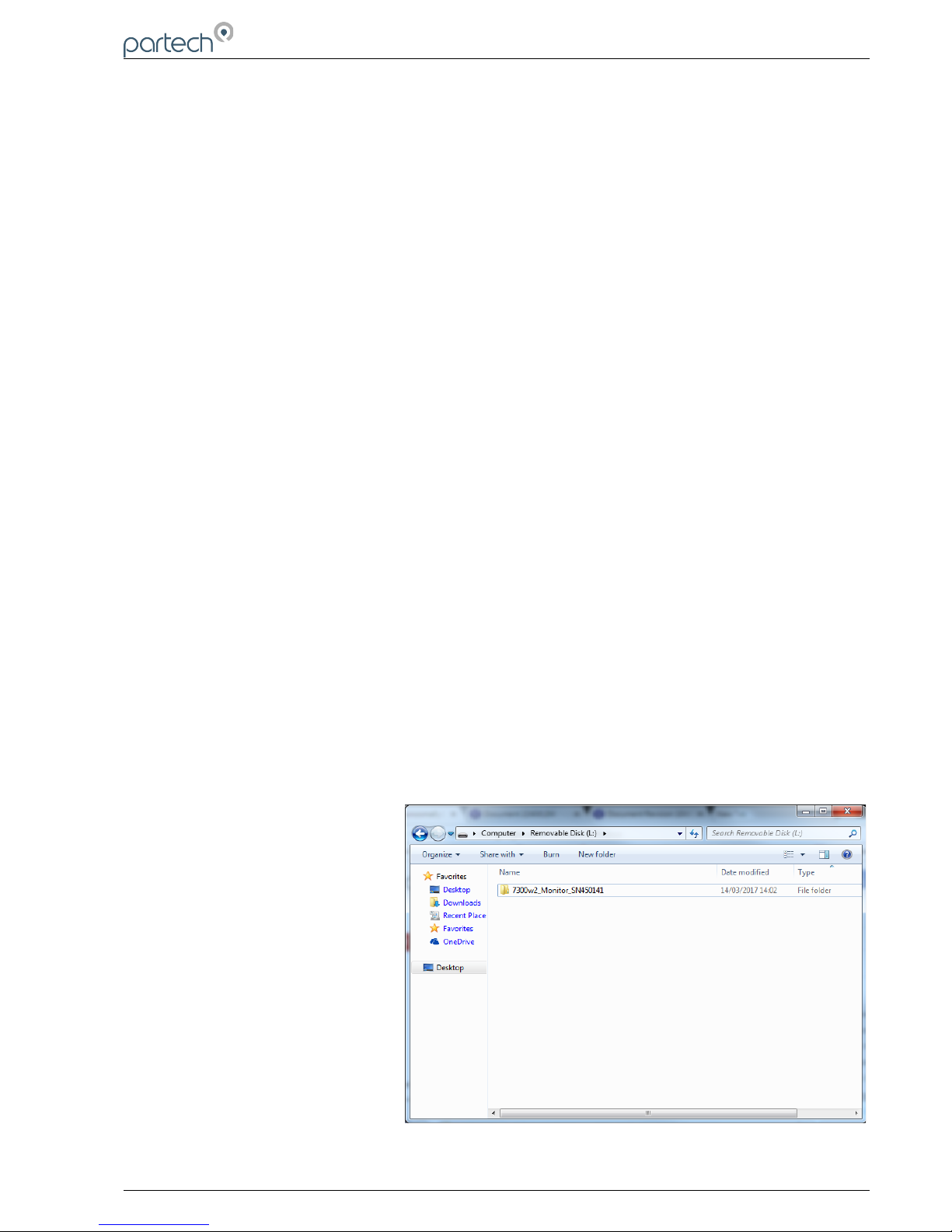
7300w² Monitor Instruction Manual
6.9 Logging
The 7300w² Monitor will automatically log the measurement values and status. This log file can then
be saved on a USB memory stick for review on a PC. Monitor can store 10,000 records. The data will
not be lost, even if the 7300 is powered down.
6.9.1 Logging Status
This screen displays diagnostic information about the status of the logging, it is not necessary to use
this screen in day to day operation.
6.9.2 Download Logged Data to USB
Selecting this option will output the logfile to the USB memory stick. If no memory stick is present, the
7300w² will display a warning.
6.9.3 Logging Interval
This settings allows the user to change the logging interval. By default this is set to 300 seconds (5
minutes). This means once every five minutes the 7300w² Monitor will store all measurements and
status. The 7300w² Monitor can be set to log between once a second and once per hour. The 7300w²
That gives a logging range of just under 3 hours, to 416 days. The 7300w² Monitor will store the
information in
6.9.4 Logging Mode
There are three modes available
1) Continuous
In this mode, the 7300w² Monitor will always log and store the latest data. When the memory is full it
will overwrite the oldest data in the memory first. This is the recommended mode of operation.
2) Single Shot
In this mode, the 7300w² Monitor will stop logging as soon as the memory is full (10,000 records). This
mode is particularly useful when a specific event in time must be logged.
3) Disabled
In this mode, the 7300w² Monitor will not log and store any data.
6.9.5 Logging Reset
This will erase all stored records.
6.9.6 Locating the Log File
When 'Download Logged Data to
USB' is selected, the Logfile will be
saved in a folder called
7300w2_Monitor_SNxxxxxx
where 'xxxxxx' is the serial number
of the 7300w² Monitor.
224081IM Issue 22 Issue Date 27/03/2018 ` Page 33 of 46
Page 34
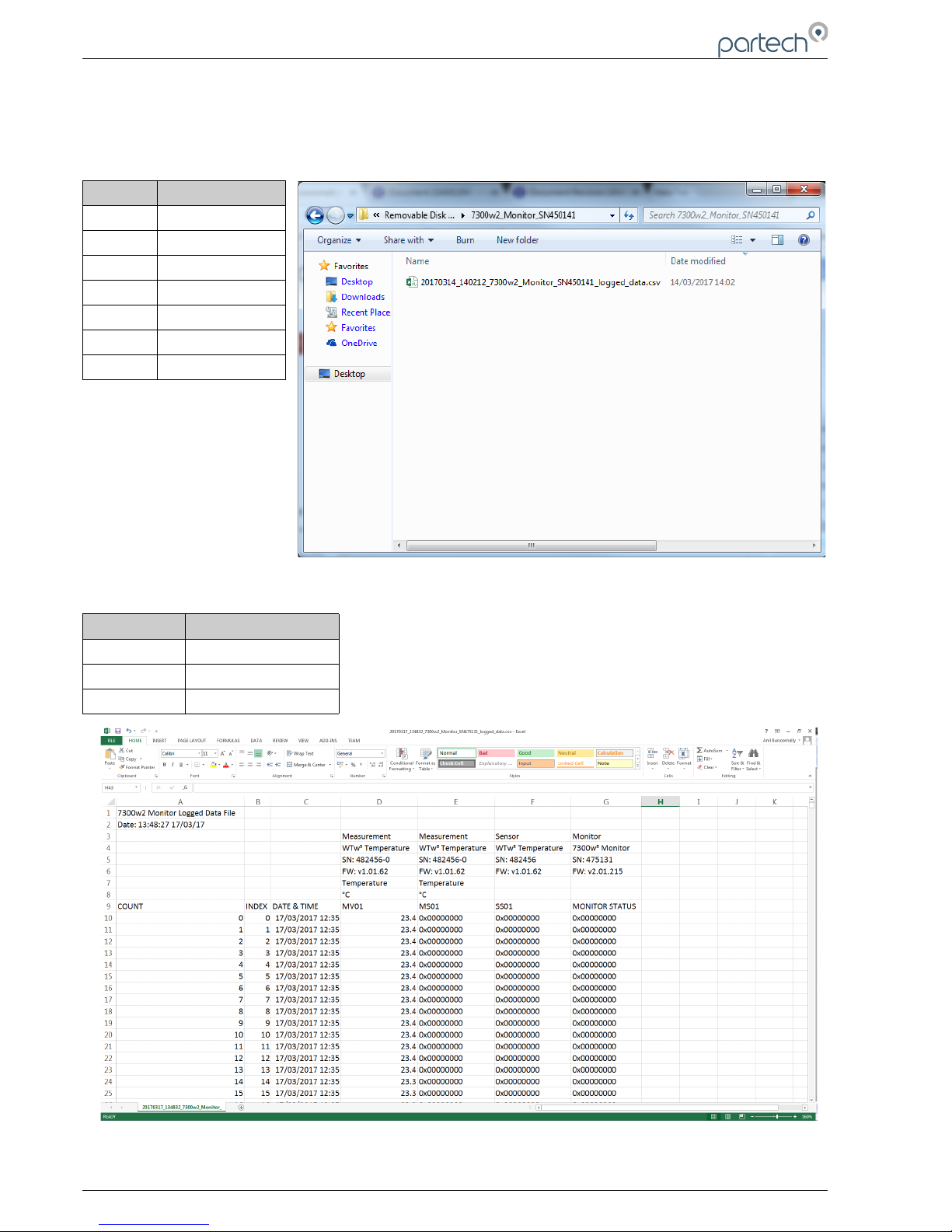
7300w² Monitor Instruction Manual
The file will be named in the following Format:
YYMMDD_HHMMSS_7300w2_Monitor_SNxxxxxx_logged_data.csv
Key:
Letters Meaning
YYYY Year
MM Month
DD Date
HH Hour
MM Minutes
SS Seconds
xxxxxx Serial Number
Opening the Log File
Abbreviation Meaning
MV Measurement Value
MS Measurement Status
SS Sensor Status
For details on decoding the status columns please contact Partech support.
Page 34 of 46 224081IM Issue 22 Issue Date 27/03/2018
The logfile is in a CSV (Comma Separated Variable) format. It is
intended to be opened in a standard spreadsheet application e.g.
Microsoft Excel or Open Office Calc.
Opening the file should result in correctly formatted columns displaying
the data.
Page 35

7300w² Monitor Instruction Manual
7 Service Mode
The 7300w² Monitor has a set of hidden menus that provide access to a wide range of diagnostic
information and tools. These may be required when investigating faults with the Monitor or Sensors
including detailed calibration information. These menus are intended for use by Partech engineers or
engineers who have been provided with additional training.
Several Menus have additional options when Service Mode is activated. These are;
Main Menu – Diagnostics containing information on the factory set up of the 7300w² Monitor.
Monitor Config Menu – Enable Factory Mode and Monitor Config Adv. These menu options
are explained further in 7.1.1 and 7.1.2.
Sensor Config – Diagnostics containing information for the selected Sensor. Further
information will be available in the respective sensor manual.
Measurement Config – Diagnostics containing signal and calibration details of the
measurement. Further information will be available in the respective sensor manual.
Output Config – 0/4 and 20 mA Offset allows adjustment to the analogue output, see 7.1.3.
It is assumed the operator entering Service Mode is already familiar with navigating the 7300w²
menus, therefore a simplified notation is used in this section. For example:
• Main Menu > Monitor Config > Bleeper > ON
7.1 Access to Service Mode
Enable Service Mode as follows:
• Main Menu > Monitor Config > Enable Service Mode > Password 00037
You will notice that the top line of the display is now in reverse, white on black text and SM (Service
Mode) is displayed in the top left corner.
Exit Service Mode as follows:
• Main Menu > Monitor Config > Disable Service Mode > OK
The Monitor Config menu now contains two more options.
7.1.1 Enable Factory Mode
Factory mode is not available to the user. This menu allows the monitor to be configured during factory set
up.
Please note that adjustments made using this menus could invalidate any warranty claim unless carried out
under the guidance of a Partech engineer or engineer authorised by Partech.
7.1.2 Monitor Config Adv.
Under this menu there are five options.
1. Reset User Config
This option allows the monitor to be reset back to the factory default settings. Once selected, all
sensor configurations, Alarm configurations and Output Configurations will be erased.
Measurement Pulse
This option displays a small dot next to any active measurement on the measurement screen each
time the monitor communicates with the sensor. This is useful during fault diagnostics.
2. Digital Input Config
224081IM Issue 22 Issue Date 27/03/2018 ` Page 35 of 46
Page 36

7300w² Monitor Instruction Manual
This option allows the configuration of the on-board I/O of the monitor. These Inputs are not currently
available to the user.
3. Digital Output Config
This option allows the configuration of the on-board I/O of the monitor. These outputs are not
currently available to the user.
4. Hold Output Timeout
This menu enables all outputs to be frozen for a pre-determined period. This option is useful for a
process application where the removal of the sensor from the sample for manual cleaning could
cause a high reading resulting in a change in the process. Once enabled, all Relays and 4-20mA
signals will be frozen at their current state.
The default setting is “Disabled”, and will not show in the main menu.
To enable HOLD OUTPUTS, follow this procedure:
1. Ensure the monitor is in Service Mode as explained at the beginning of this chapter. “SM” will be
displayed in the top left hand corner of the MAIN MENU bar.
2. Navigate to HOLD OUTPUT TIMEOUT option as follows:
3. Main Menu > Monitor Config > Monitor Config Adv > Hold Output Timeout.
4. Five options are available:
5. Disable – Disabled and not displayed.
6. 5 Minutes – Once set to HOLD, the outputs will hold for 5 mins before resetting.
7. 60 Minutes – Once set to HOLD, the outputs will hold for 60 mins before resetting.
8. 240 Minutes – Once set to HOLD, the outputs will hold for 240 mins before resetting.
9. Never – Will hold outputs indefinitely. Must be manually reset.
Once enabled, the HOLD OUTPUTS menu will appear at the beginning of the MAIN MENU.
Once configured, select HOLD OUTPUTS. You will then be asked for a password. This password is
the same password as configured for LOCK CONFIG. The default password is 01000.
With the outputs on HOLD the bottom display bar will show “OUTPUT HOLD”.
To release the HOLD function, select RELEASE OUTPUTS from the Main Menu. Again the
password will be required.
7.1.3 Output 0/4mA and 20mA Offset
The 0/4mA and 20mA offset allows the analogue outputs to be manually adjusted. The monitor is
supplied with the analogue outputs accurately calibrated, however site conditions often require the
analogue outputs to be increased to compensate for errors in the external wiring of the analogue
loop.
Adjustment of the Offset does not effect the factory calibration of the monitor, but simply forces the
output to be offset from the calibrated values.
If the output has been configured as a 0-20mA output, all 4mA menus will be replaced with 0mA
menus. The offset function for 0mA is the same as for the 4mA offset, except a minus value will not
be allowed for 0mA.
Navigate to “4 mA Offset” option as follows:
Main Menu > Output Config > Output # Config > Output # (M) 4mA Offset
Page 36 of 46 224081IM Issue 22 Issue Date 27/03/2018
Page 37

7300w² Monitor Instruction Manual
Navigate to “20mA Offset” option as follows:
Main Menu > Output Config > Output # Config > Output # (M) 20mA Offset
First set the 4mA offset. Adjustment of the 4mA output will also effect the 20mA output, i.e. increasing
the 4mA output by 0.5mA will also add 0.5mA to the 20mA output. Once the 4mA output has been
adjusted as required, the 20mA can then be adjusted if required.
224081IM Issue 22 Issue Date 27/03/2018 ` Page 37 of 46
Page 38

7300w² Monitor Instruction Manual
8 Menu Tree
Below is the menu structure of the 7300w² Monitor:
Menus in Green are only available in service mode or options selected in service mode.
Menus in Blue are only available when an expansion box is connected.
Menus in Red are intended for Partech Technicians only.
Main Menu
Hold Outputs (when Service Mode is enabled)
Monitor Config
Bleeper
Backlight
Contrast
Language
Set Date/Time
Enable Service Mode
Password 00037
Disable Service Mode
Enable Factory Mode
Password ?????
Monitor Config Adv
Reset User Config
Measurement Pules
Digital Input Config
Digital Output Config
Hold Output Timeout
Enter Bootloader
Mount USB Memory
Expansion Config
Expansion Status
Add Expansion
E:# WW² EB 8A 8R
E:# Remove
E:# Modbus Addressing
E:# Comm Fail Timeout
E:# Output Comm Fail
E:# Relay Comm Fail
Sensor Config
Sensor Status
Add Sensor
S:01 Sensor Type Option
Measurement Config
Measurement Status
Add Measurement
M:01 Measurement Option (S:01)
Alarm Config (# = refers to 1 - 8 alarms available depending on specification)
((M) = refers to Monitor, whereas (E:1) refers to Expansion Box No.1)
Alarm Status
Alarm # Config
Alarm # (M) Info
Alarm # (M) Measurement
Alarm # (M) Type
Alarm # (M) Value
Alarm # (M) Hysteresis
Alarm # (M) Fault Setup
Alarm # (M) Set Delay
Alarm # (M) Reset Delay
Alarm # (M) Test
Alarm # (M) Test Cycle
Output Config (# = refers to 1 - 8 alarms available depending on specification)
Page 38 of 46 224081IM Issue 22 Issue Date 27/03/2018
Page 39

7300w² Monitor Instruction Manual
((M) = refers to Monitor, whereas (E:1) refers to Expansion Box No.1)
Output Status
Output # Config
Output # (M) Info
Output # (M) Measurement
Output # (M) Type
Output # (M) 4mA
Output # (M) 20mA
Output # (M) Fault Mode
Output # (M) Fault Setup
Output # (M) Test
Output # (M) Test Cycle
Output # (M) 4mA Offset
Output # (M) 20mA Offset
Information
Software Version
Contact Information
Diagnostics
Monitor Info
Anybus Info
Sensor Get Debug
Download Debug Log
Download Modbus Log
User U8 Values
User U16 Values
User U32 Values
User S32 Values
Factory U8 Values
Factory U16 Values
Factory U32 Values
Factory S32 Values
Diagnostic Download
Menu Tree
Debug Text Output
Debug RS485
Sensor Type Summary
Lock Config
Lock Monitor
Change Password
Set Auto Lock
Logging
Logging Status
Download Logged Data to USB
Logging Interval
Logging Mode
Logging Reset
Download Logged Data to RS232
224081IM Issue 22 Issue Date 27/03/2018 ` Page 39 of 46
Page 40
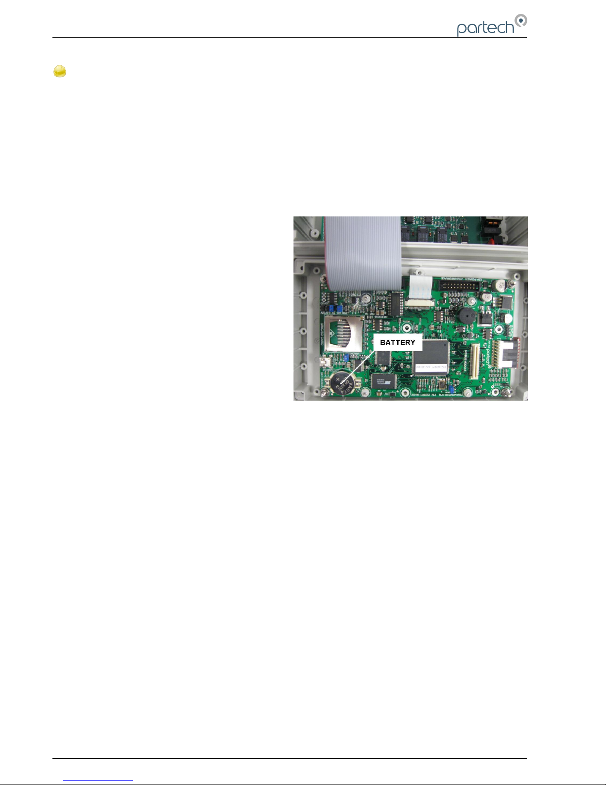
7300w² Monitor Instruction Manual
9 Maintenance
9.1 On-Board Battery Backup Replacement
The monitor is fitted with a battery backup for the real time clock function. Failure of the battery will
only effect the time (all parameters, settings and process data are stored electronically and is not
effected by a failed battery).
Fitted is a Lithium CR2032 battery. Under normal operating conditions, the battery should not require
replacement for at least 5 years. However, we advise the battery is replaced if the monitor has been
kept in storage or remained off power for more than 3 years.
The battery is located behind the main display panel. To access the battery, follow these steps.
1, Ensure the monitor is isolated or disconnected
from HAZARDOUS LIVE voltages before access.
2, Remove the four plastic caps located on the
corners of the display using a small flat bladed
screwdriver to reveal the screws.
3, Unscrew the four screws and gently lower the
panel. Take care as the display is connected to the
back board via a ribbon cable.
4, With the display panel turned over and hanging
upside-down by the ribbon cable (see photo right),
the battery can be located on the bottom left corner
of the display board. Disconnect the ribbon cable if
this makes access easier.
5, Using a flat bladed screwdriver, gently prise out
the battery and replace.
6, Return the display panel back to the enclosure (first reconnect the ribbon cable if disconnected),
and screw back. Refit the screw covers.
7, Reset the Monitor time as described in section 6.1.4 of this manual.
Page 40 of 46 224081IM Issue 22 Issue Date 27/03/2018
Page 41

7300w² Monitor Instruction Manual
10 Faults
The majority of error messages are related to the performance of the sensors and/or measurements.
These messages are generated by and stored in the sensor. Please refer to the sensor manual for full
description of these messages.
Error messages are displayed in a number of locations: under the displayed value (usually in
conjunction with a flashing display), in the bottom information line and in the Info and Diagnostic
sections.
Whenever a 'Status' is reported as OK(0) the monitor is reporting a healthy system performance and
set up. The (0) relates to the no fault state of the monitor's operating system.
10.1 Monitor Error Messages
The only error message generated by the monitor is:
COMM FAULT
This indicates a fault with the communication between the monitor and one or more sensors. This is
sometimes reported with a (1) on the end of the message. The (1) refers the to the fault state of the
monitor's operating system and is not an indication of the number of the measurement at fault, nor the
number of sensors which are not communicating properly.
Before reacting to this message, please observe the monitor for a few minutes. The nature of the
ModTechw² protocol being used for communication between the monitor and sensors will occasionally
report transient errors which will clear themselves.
Communication errors can be caused by faulty or poorly installed cable, please check the connections
before taking any further action.
If the problem persists, contact Partech or your local Partech representative.
10.2 Sensor Error Messages
The majority of error messages displayed on the monitor will be reported by the sensor, these
messages will vary between sensor type. Sensors are self diagnostic and are able to detect out of
range, clean fault and other general error conditions.
Please refer to the sensor manual for specific sensor faults.
224081IM Issue 22 Issue Date 27/03/2018 ` Page 41 of 46
Page 42

7300w² Monitor Instruction Manual
11 Technical Support
Technical Support is available by phone, fax, or email, the details of which are shown below.
• Phone: +44 (0) 1726 879800
• Fax: +44 (0) 1726 879801
• Email: [email protected]
• Website: www.partech.co.uk
To enable us to provide quick and accurate technical support please have the following information ready
when you contact us:
• Serial Number or original purchase details.
• Sensor Type, and Serial Number.
• Application details.
• Description of fault.
• Digital photos can also be useful to determine correct installation and suitability to the application.
11.1 Returning Equipment for Repair
If equipment needs to be returned to Partech for repair or service the following address should be used:
SERVICE DEPARTMENT
PARTECH INSTRUMENTS
ROCKHILL BUSINESS PARK
HIGHER BUGLE
ST AUSTELL
CORNWALL
PL26 8RA
UNITED KINGDOM
Please include the following information with the returned equipment. Also ensure that sensor is clean and
adequately protected for transportation (Advice on packing can be provided by our service department).
• Contact name and phone number of person authorising the repair
• Site details including application sample point
• Return address for equipment
• Description of fault or service required
• Any special safety precautions because of nature of application
Page 42 of 46 224081IM Issue 22 Issue Date 27/03/2018
Page 43

7300w² Monitor Instruction Manual
12 Technical Specification
12.1 Physical
Dimensions ....................................213 x 185 x 95mm (HxWxD)
Enclosure Material..........................Polycarbonate (PC)
Weight.............................................1.4Kg
Temperature....................................-20 to +60 C, 0-95% Relative Humidity, Non-Condensing
Mounting......................................... Wall or Rail Mounting Bracket or Enclosure Option Available
Cable Entries...................................1x M20, 4x M16, 1x M12
12.2 User Interface
Display ...........................................Graphic LCD, Black on White, Transreflective
Viewing Area...................................78 x 59mm
Backlight..........................................Always ON / OFF, User Adjustable ON/OFF after key press
Membrane Keypad..........................High quality 6 key membrane with Pillow Embossed 20mm dia Buttons
12.3 Electrical
Operation Voltage: .........................100 to 240VAC, 50/60Hz
or 12 to 24VDC
Power Rating...................................0.8A AC, 30W DC (Power consumption may increase for 2 or more sensors)
Terminal Wire Size..........................Max 2.5mm² cores
Analogue Outputs...........................0/4–20mA, Max load 750 ohms
Digital/Relay Outputs......................3 (Reduced to 1 Relay for PROFIBUS)
Relay Type......................................SPCO, Max 230VAC Switching Voltage
Relay Rating....................................Max 5A @ 30VDC / 230VAC
Auxiliary Connections......................Configurable for remote Input, Output or 12VDC Aux Power
12.4 Sensors and Optional Interfaces
Sensor Communication...................ModTechw² Protocol (Specifically developed for w² range of sensors)
ModTechw² Cable Specification......2 Twisted Pair (Red/Black, Green/White), 24AWG screened with drain wire
224081IM Issue 22 Issue Date 27/03/2018 ` Page 43 of 46
Page 44

7300w² Monitor Instruction Manual
13 Declaration of Conformity
DECLARATION OF CONFORMITY
to EMC and Low Voltage Directives
We, Partech Instruments, Rockhill Business Park, Higher Bugle, St Austell,
Cornwall, United Kingdom, declare under our sole responsibility that the product
to which this declaration relates:
Product Name: 7300w² Monitor and associated ancillary devices
Model Number(s): 223160, 226161, 223162, 223163
Is in conformity with the standards noted below:
EN 61326:2008 – Electrical equipment for measurement, control and laboratory use
– EMC requirements
BS EN 61010-1:2001 IEC 61010-1: 2001 – Safety Requirements for electrical
equipment, control and laboratory use
Following the provisions of European Directives:
2004/108/EC EU EMC Directive
2006/95/EC Low Voltage Directive
Roger Henderson, Technical Director, 6th December 2010
for Partech Instruments, Rockhill Business Park, Higher Bugle, St Austell, Cornwall PL26 8RA, UK
Page 44 of 46 224081IM Issue 22 Issue Date 27/03/2018
Page 45

7300w² Monitor Instruction Manual
224081IM Issue 22 Issue Date 27/03/2018 ` Page 45 of 46
Page 46

Partech Instruments
Rockhill Business Park, Higher Bugle, St Austell, Cornwall,PL26
8RA,UK
Tel: +44(0)1726 879800
Email: [email protected] Web: www.partech.co.uk
 Loading...