

Page 1

INSTRUCTION MANUAL
7200 Monitor
Field Mount
Page 2

** This page is intentionally left blank **
Page 3

7200 Monitor Instruction Manual
Table of Contents
1 Health & Safety Information..........................................................................................................................................6
2 Introduction...................................................................................................................................................................7
2.1 General..............................................................................................................................................................7
2.2 Display...............................................................................................................................................................7
2.3 Key Pad.............................................................................................................................................................7
2.4 Alarms................................................................................................................................................................7
2.5 Analogue Output................................................................................................................................................7
2.6 Sensors..............................................................................................................................................................7
3 Manual Conventions.....................................................................................................................................................8
4 MCERTS Product Certification......................................................................................................................................9
5 Installation...................................................................................................................................................................10
5.1 Location...........................................................................................................................................................10
5.2 Mounting..........................................................................................................................................................10
5.3 Electrical Connections.....................................................................................................................................11
6 Basic Operational........................................................................................................................................................13
6.1 Measure Mode.................................................................................................................................................13
6.2 Measurement Cycle.........................................................................................................................................13
6.3 Display.............................................................................................................................................................13
7 Configuration...............................................................................................................................................................14
7.1 Menu Mode......................................................................................................................................................14
7.2 Data Entry........................................................................................................................................................15
7.2.1 User List Selection....................................................................................................................................15
7.2.2 User Value Entry.......................................................................................................................................15
7.2.3 User Text Entry.........................................................................................................................................16
8 Calibration...................................................................................................................................................................17
8.1 Calibration General..........................................................................................................................................17
8.2 Methods of Calibration.....................................................................................................................................17
8.3 Preparing for Calibration..................................................................................................................................17
8.4 Calibration Wizard............................................................................................................................................18
8.5 Set Zero...........................................................................................................................................................18
8.6 Set Span..........................................................................................................................................................19
8.7 Take Sample....................................................................................................................................................20
8.8 Enter sample Result.........................................................................................................................................20
9 Setup Wizard..............................................................................................................................................................21
10 Alarm outputs............................................................................................................................................................22
10.1 Alarm Value...................................................................................................................................................22
10.2 Alarm Type.....................................................................................................................................................22
10.3 Alarm Hysteresis............................................................................................................................................22
167300IM-Issue 12 Issue Date 14/10/2014 Page 3 of 50
Page 4

7200 Monitor Instruction Manual
10.4 Fault Alarm Setup..........................................................................................................................................23
10.5 Delay to Set...................................................................................................................................................23
10.6 Delay to Reset...............................................................................................................................................23
10.7 Test Alarm Output..........................................................................................................................................23
10.8 Alarm Test Cycle............................................................................................................................................23
11 Analogue Output.......................................................................................................................................................24
11.1 Set Output Low..............................................................................................................................................24
11.2 Set Output High.............................................................................................................................................24
11.3 Select Output Type........................................................................................................................................24
11.4 Fault Output Mode.........................................................................................................................................25
11.5 Fault Output Setup.........................................................................................................................................25
11.6 Test Output....................................................................................................................................................25
11.7 Output Test Cycle..........................................................................................................................................25
12 Sensor Configuration................................................................................................................................................26
12.1 Select Sensor Type........................................................................................................................................27
12.2 Select Display Range.....................................................................................................................................27
12.3 Set Damping Rate..........................................................................................................................................28
12.4 Air Clean Option.............................................................................................................................................28
13 Advanced Sensor Setup...........................................................................................................................................29
14 Instrument Setup.......................................................................................................................................................30
14.1 Measurement Title.........................................................................................................................................30
14.2 Display Units..................................................................................................................................................30
14.3 Display Contrast.............................................................................................................................................30
14.4 Bleeper..........................................................................................................................................................31
14.5 Backlight........................................................................................................................................................31
14.6 Language.......................................................................................................................................................31
14.7 Change Password..........................................................................................................................................31
14.8 Reset Instrument............................................................................................................................................31
15 Clean Setup..............................................................................................................................................................32
15.1 Set Clean Interval..........................................................................................................................................32
15.2 Clean Mode....................................................................................................................................................32
15.3 Clean Information...........................................................................................................................................33
15.4 Service Life....................................................................................................................................................33
15.5 Reset Clean Count.........................................................................................................................................33
16 Air Clean Setup.........................................................................................................................................................34
16.1 Set Clean Interval..........................................................................................................................................34
16.2 Clean Duration...............................................................................................................................................34
16.3 Settling Time..................................................................................................................................................34
16.4 Clean Information...........................................................................................................................................35
16.5 Service Life....................................................................................................................................................35
16.6 Reset Clean Count.........................................................................................................................................35
Page 4 of 50 167300IM-Issue 12 Issue Date 14/10/2014
Page 5

7200 Monitor Instruction Manual
17 Diagnostics...............................................................................................................................................................36
17.1 Sensor Input...................................................................................................................................................36
17.2 Sensor %.......................................................................................................................................................36
17.3 Calibration Values..........................................................................................................................................36
17.4 Factory Values...............................................................................................................................................36
17.5 Diagnostic Values..........................................................................................................................................36
17.6 Diagnostic Download.....................................................................................................................................36
17.7 Opto Inputs....................................................................................................................................................36
17.8 ADC Inputs.....................................................................................................................................................36
18 Information................................................................................................................................................................37
18.1 Statistics.........................................................................................................................................................37
18.2 Software Version............................................................................................................................................37
18.3 Contact Information........................................................................................................................................37
19 Instrument Security...................................................................................................................................................38
19.1 Lock Instrument.............................................................................................................................................38
19.2 Change Password..........................................................................................................................................38
20 Error Messages.........................................................................................................................................................39
20.1 Sensor...........................................................................................................................................................39
20.2 Measure Mode...............................................................................................................................................39
20.3 Self Clean Sensors........................................................................................................................................39
20.4 Calibration......................................................................................................................................................40
20.5 Air Clean Systems.........................................................................................................................................40
21 Menu Structure.........................................................................................................................................................41
22 Sensor Defaults........................................................................................................................................................42
23 Preparation of Fullers Earth Solution........................................................................................................................43
24 Preparation of Formazin Turbidity Standardise.........................................................................................................44
25 Technical Support.....................................................................................................................................................45
25.1 Returning Equipment for Repair.....................................................................................................................45
26 Technical Specification.............................................................................................................................................46
26.1 General..........................................................................................................................................................46
26.2 Alarm Outputs................................................................................................................................................46
26.3 Analogue Output............................................................................................................................................46
26.4 EMC...............................................................................................................................................................46
26.5 Field Mount....................................................................................................................................................46
27 Declaration of Conformity..........................................................................................................................................47
167300IM-Issue 12 Issue Date 14/10/2014 Page 5 of 50
Page 6

7200 Monitor Instruction Manual
1 Health & Safety Information
The following information is a guide and does not in anyway replace legal requirements for the handling of the
equipment and chemicals or any safe working practise defined outside of this manual.
Care needs to be taken to ensure that the system can be accessed safely for calibration and maintenance.
To ensure that our products are safe and without risk to health, the following must be noted:
1. The relevant sections of these instructions must be read carefully before proceeding.
2. Warning labels on containers and packaging must be observed.
3. Installation, operation, maintenance and servicing must only be carried out by suitably qualified personnel and
in accordance with the information given.
4. Standard safety precautions must be taken to avoid the possibility of an accident occurring in conditions of
high pressure and/or high temperature.
5. Chemicals should be stored appropriately and protected from temperature extremes. Follow normal safe
handling procedures.
6. When disposing of chemicals ensure that no two chemicals are mixed.
Page 6 of 50 167300IM-Issue 12 Issue Date 14/10/2014
Page 7

7200 Monitor Instruction Manual
2 Introduction
2.1 General
The 7200 Monitor is used for processing and displaying the output signal from a Partech sensor. It combines a clear
display of the measured parameter, a simple user interface, with good flexibility to enable configuration to satisfy the
users needs. For remote signalling the 7200 has two alarm outputs and a single analogue output.
The 7200 Monitor has an IP65 enclosure and is suitable for outdoor use however a protective cover or outer enclosure
is recommended to further protect the instrument from the elements.
2.2 Display
The 7200 display indicates the measured value with large numerals for good visibility with an additional status line that
shows the current state of the alarm outputs, analogue output and any faults that are present. The display has a
backlight to enable use of the monitor in low light conditions and also has a user settable contrast.
The measurement title, units and display range can all be user set to suit the sensor being used and the parameter
being monitored.
2.3 Key Pad
A six key tactile membrane keypad is used for all configuration and operation of the 7200 Monitor, each key has a very
positive operation enabling use even whilst wearing gloves.
2.4 Alarms
Two user configurable alarms are provided within the 7200, which can be used to signal high, low or fault alarm
conditions. Each alarm output is a single pole change over relay which is normally energised (no alarm present) and
de-energises when an alarm occurs (fail safe).
2.5 Analogue Output
The 7200 Monitor has a single analogue output that can be configured for voltage or current operation and can be set
to operate over the whole measuring range or a portion of the measuring range. The output can also be configured for
reverse operation (i.e. 20 to 4mA) should this be required.
When a fault condition occurs (see faults), the user can select whether the output indicates the last valid
measurement, its maximum output value or its minimum output value. This is useful when the alarm outputs are not
used and it is necessary to remotely determine the instrument’s state.
2.6 Sensors
The 7200 Monitor can be used with the following Partech sensors:
TT Series TT2000LA, TT2000LS, TT2i, TT10i, TT12i, TT20i
IR Series IR8, IR15, IR40, IR100, IR12LS
IL Series IL55, IL55BV2
ST Series ST20 Range 0-xxxxx
167300IM-Issue 12 Issue Date 14/10/2014 Page 7 of 50
Page 8

7200 Monitor Instruction Manual
3 Manual Conventions
This instruction manual describes the configuration and operation of the 7200 Monitor and where required includes
some information regarding sensors. It is therefore very important that it is used in conjunction with the relevant sensor
instruction manual. All dimensions stated in this manual are in millimetres unless otherwise stated.
The manual has been written on the basis that the user has a basic knowledge of instrumentation and an
understanding of the type of measurement being made. Training in the use of the 7200 Monitor can be provided by
Partech, please contact sales for further information.
Page 8 of 50 167300IM-Issue 12 Issue Date 14/10/2014
Page 9

7200 Monitor Instruction Manual
4 MCERTS Product Certification
Increasingly, with 'Modern Regulation' and in order to strengthen its auditing of operators' self-monitoring
arrangements, the Environment Agency is moving towards more efficient regulation through Operator and Pollution
Risk Appraisal (OPRA), Operator Monitoring Assessment (OMA) and it's Monitoring Certification Scheme (MCERTS)
MCERTS is now well established and is seen as a mark of quality. It provides a framework within which environmental
measurements can be made in accordance with the Agency's quality requirements. The scheme covers a range of
monitoring, sampling and inspection activities including product certification. Partech Instruments manufacture and
supply the first certified Turbidity Monitoring System under the Environment Agency's MCERTS scheme for
Continuous Water Monitoring equipment (CWM's).
The current performance standard for CWM's is available at:
https://www.gov.uk/government/uploads/system/uploads/attachment_data/file/301541/performance_standards_and_te
st_procedures_for_continuous_water_monitoring_equipment_part_1.pdf
https://www.gov.uk/government/uploads/system/uploads/attachment_data/file/301546/performance_standards_and_te
st_procedures_for_continuous_water_monitoring_equipment_part_2.pdf
The scheme is operated on behalf of the Environment Agency by Sira. The United Kingdom Accreditation Service
(UKAS) accredits Sira to undertake the product and personnel certification activities which underpin the MCERTS
scheme. The scheme provides a framework within which instruments and measurements can be made in accordance
with the Agency's quality requirements.
Partech Instrument's Certified Turbidity System consists of the 7200 Monitor and Turbi-Tech 2000LS Sensor.
The system underwent laboratory testing in accordance with the MCERTS performance standard and can only be
described as an MCERTS certified system when installed and operated as a system in accordance with recommended
procedures. 7200 Monitors sold with any other sensor are not certified.
The system has been certified in the ranges 0-50FTU/FNU and 0-500FTU/FNU and to measure Turbidity.
Partech's Turbidity MCERTS certificate is available at:
http://www.siraenvironmental.com/UserDocs/MCERTS/MC06008303.pdf
For further information on the various MCERTS schemes visit:
http://www.mcerts.net/
167300IM-Issue 12 Issue Date 14/10/2014 Page 9 of 50
Page 10
7200 Monitor Instruction Manual
5 Installation
5.1 Location
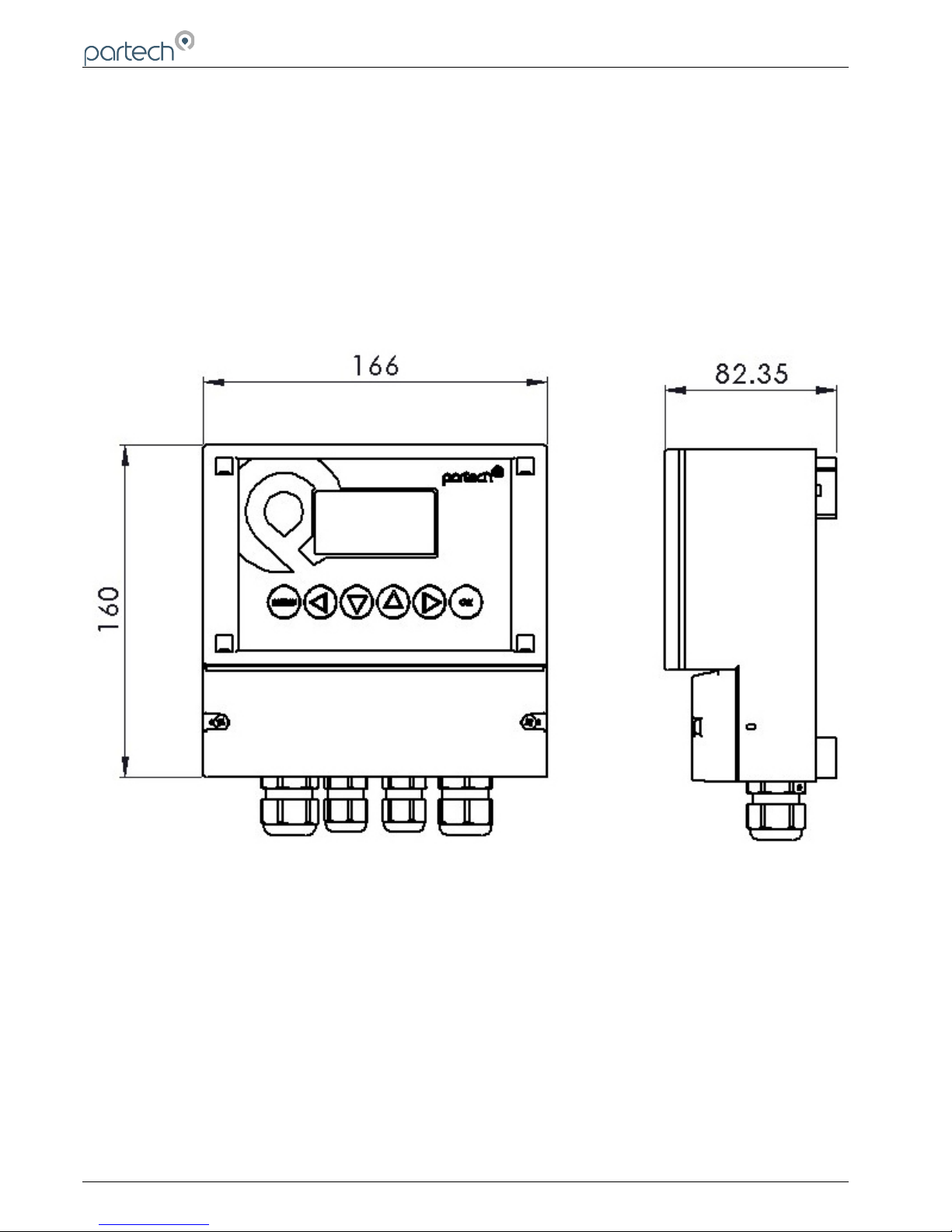
The field mounting version of the 7200 Monitor is housed in an IP65 enclosure and therefore is suitable for mounting
outdoors, preferably located close to the sensor. It is advisable to mount the monitor in a location where it has some
protection from the elements, this could be inside a GRP or metal cabinet, in a control room, or with a protective
shield.
It is recommended that the monitor is located close to the sensor to simplify the set up and calibration of the system
thus avoiding long walks between monitor and sensor.
Note: The maximum length of cable between the monitor and sensor is 100 metres.
7200 Field Mount
5.2 Mounting
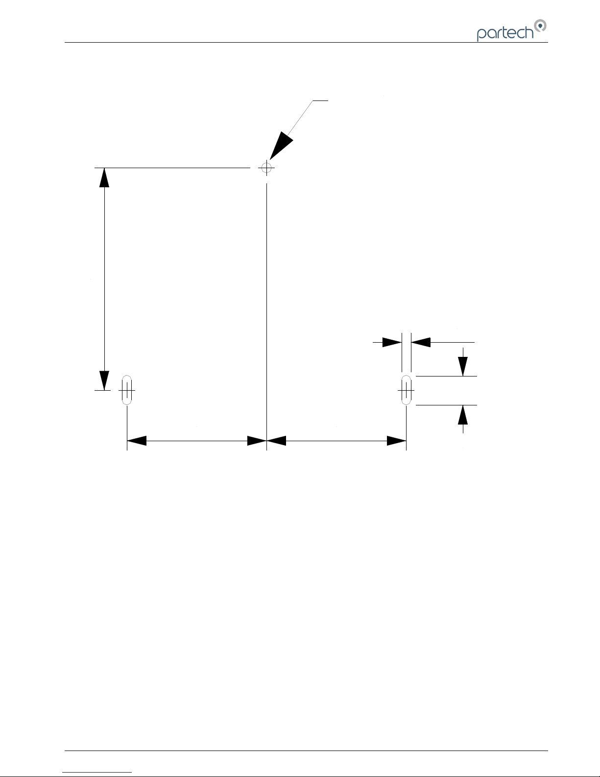
The 7200 Monitor enclosure is designed for wall mounting, the hole positions required for this are shown below. A
range of mounting hardware (such as handrail brackets, protective hoods and sensor brackets) is available from
Partech, further details are available on request.
Page 10 of 50 167300IM-Issue 12 Issue Date 14/10/2014
Page 11
7200 Monitor Instruction Manual
7200 Field Mount mounting hole positions
5.3 Electrical Connections
The 7200 Monitor electrical connections can be accessed by removing the terminal compartment cover.
The electrical supply to the unit should be installed such that there is a means of isolating the supply to the unit and
the supply is protected with a fuse or trip. The instrument does have a supply fuse fitted internally.
WARNING: DISCONNECT THE MAINS SUPPLY BEFORE REMOVING THE TERMINAL COVER
The 7200 Monitor is supplied fitted with two PG11 cable glands fitted and has provision for a further two PG11 glands.
If the cable being used is too large for the PG11 glands, the cable must be terminated externally to the unit and a
suitable cable used for connection to the 7200. If any fitted cable glands are not used, these must be sealed to prevent
the ingress of moisture into the unit.
167300IM-Issue 12 Issue Date 14/10/2014 Page 11 of 50
7 5 .5 0 7 5 .5 0
120.00
5 .0 0
5 .0 0 DIA
6 . 0 0
Page 12
7200 Monitor Instruction Manual
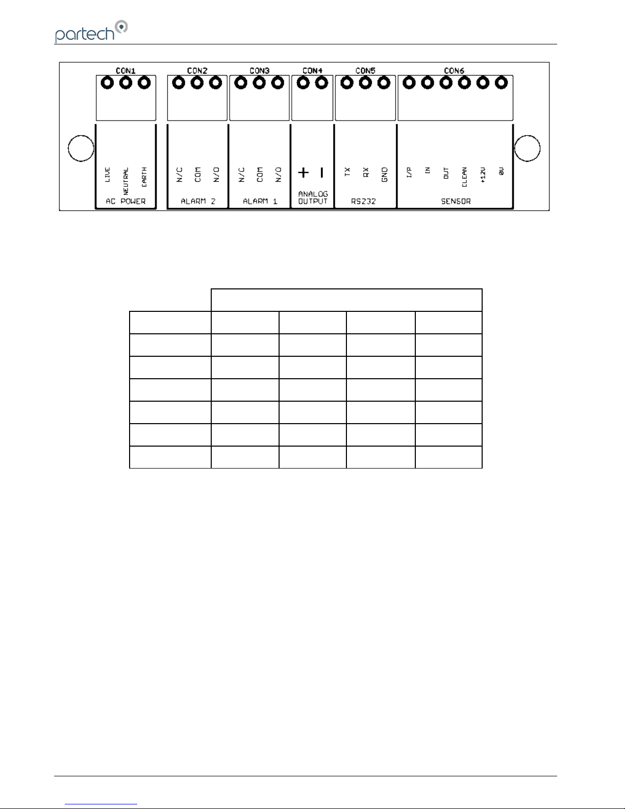
7200 Field Mount Connection Terminals
Sensor Type
Terminal TT Series IR Series IL Series ST Series
Sensor I/P Yellow White White White
In Opto Black - - -
Out Opto Red - - -
Clean Green - - -
Sensor 12V Blue Red Red Red
Sensor 0V White Black or Blue Black or Blue Black or Blue
Sensor Connection Detail
Note 1: The normal condition for the alarm outputs is when the instrument is powered and the alarm is off.
Note 2: The RS232 connections can be used to collect data from the 7200 and using a suitable serial cable for
connection to a PC. Further details of the serial connection lead are available from Partech on request.
Page 12 of 50 167300IM-Issue 12 Issue Date 14/10/2014
Page 13
7200 Monitor Instruction Manual
6 Basic Operational
6.1 Measure Mode
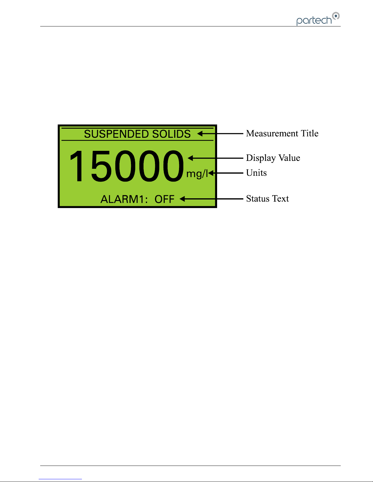
The normal operating mode for the 7200 Monitor is its measure mode and this is active when the measured value is
displayed in large numbers. Whilst in measure mode the display value is continually updated based upon the current
sensor input signal.
The display in measure mode also includes a status bar that scrolls through the status of the alarm and analogue
outputs and if the instrument is locked. The status bar is also used to indicate any instrument faults that are present.
During a clean cycle the status bar indicates the current stage of the clean cycle.
6.2 Measurement Cycle
The measurement cycle is carried out in the background at all times when the instrument is switched on regardless of
whether the instrument is in measure mode or not. It is therefore capable of updating the output signal and alarms
when the user is navigating the menu structure in order to change the instrument configuration. The monitor performs
five measurement cycles per second enabling a response time of one fifth of a second (Damping rate set to Instant –
see damping).
6.3 Display
The resolution of the displayed value is determined by the sensor range setting such that only sensible display values
are indicated, the same range also determines the calibration value range, alarm value range, and analogue output
range.
The display units and measurement title is user selectable and should be chosen to suit the parameter being
monitored and sensor being used.
167300IM-Issue 12 Issue Date 14/10/2014 Page 13 of 50
Measure Mode Display
Page 14
7200 Monitor Instruction Manual
7 Configuration
7.1 Menu Mode
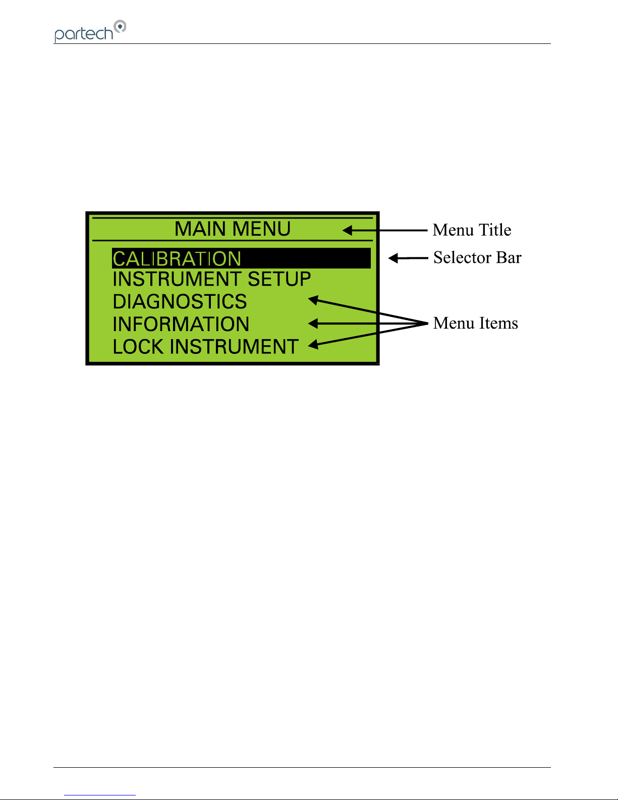
To access the main menu, press the MENU key when the instrument is in measure mode. Pressing the MENU key
when the main menu is displayed will return the instrument to the measure mode. When the main menu is displayed,
the keys can be used to move the selection bar. Pressing the OK key will activate the selected item.
If the instrument is left in any display other than measure mode, it will automatically return to menu mode after one
minute has passed with no key presses. (When the cycle alarm or cycle output facilities are being used the delay is 15
minutes)
When a sub menu is displayed, pressing the MENU key will exit the current menu and return to the previous menu. If a
menu consists of more than five items, UP and DOWN arrows will appear to indicate if there are menu items above or
below those displayed.
Page 14 of 50 167300IM-Issue 12 Issue Date 14/10/2014
Menu Display
Page 15
7200 Monitor Instruction Manual
7.2 Data Entry
To provide the user with a simply interface, the 7200 uses three methods of data entry for the setting of all the user
configurable parameters. The various methods of user data entry used on the 7200 are described below:
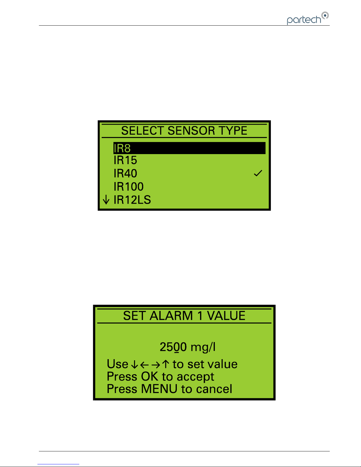
7.2.1 User List Selection
This method of user data entry is used when a selection from a predefined list of option is required such as sensor
type, display range and backlight mode. The list of possible selections will be displayed and a small tick will identify the
current setting. If the list contains more than five items, small UP and DOWN arrows will appear on the display to
indicate there are more items than that displayed. To make a selection, the selector bar can be moved using the
keys, to select the required item. Pressing the OK key will select the highlighted item and a small tick will appear next
to it. Pressing the MENU key will exit the list selection menu.
7.2.2 User Value Entry
When a numerical value is to be set, the current value will be displayed with a flashing cursor. The range of
adjustment of the value is predefined and therefore only values within this range can be entered. To adjust a value, the
keys are used to select a digit and the keys are used to increment/decrement the digit. When the new value
has been set pressing the OK key will store it and exit from the value adjustment display. If the MENU key is pressed
any changes that have been made will be lost and the value adjustment display will be exited.
167300IM-Issue 12 Issue Date 14/10/2014 Page 15 of 50
List Selection Display – note tick indicating current value
Value Entry Display
Page 16
7200 Monitor Instruction Manual
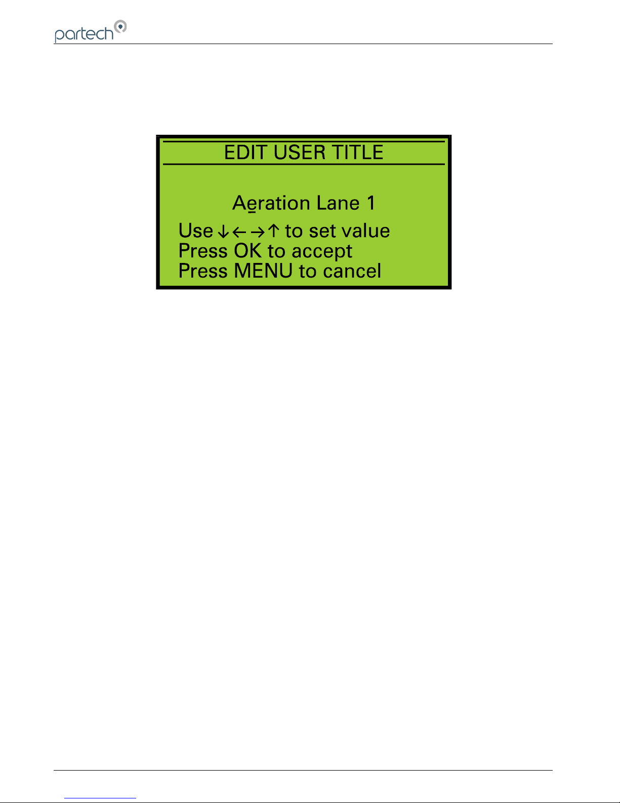
7.2.3 User Text Entry
Using this method of data entry, the user is able to enter or edit text and is used for the user defined measurement title
and units. The text string is displayed with a flashing cursor indicating the selected character. The keys are used
to select a character, and the keys to change the selected character. When all changes are complete press the OK
key to store the text string. To exit without saving changes press the MENU key.
Page 16 of 50 167300IM-Issue 12 Issue Date 14/10/2014
Text Entry Display
Page 17

7200 Monitor Instruction Manual
8 Calibration
8.1 Calibration General
Calibration of the 7200 Monitor is very important, errors in the calibration process will affect the measurement
performance of the instrument. The following section describes the various aspects of calibrating the 7200 Monitor and
has been written with the understanding that the user has knowledge of the measurement being made.
When a new system is installed, a period of 4 hours should be allowed for the equipment to stabilise before calibration
commences. This is to enable the system to adjust to the “new” ambient conditions. This should not be considered as
a warm up time from power up, it allows the system to adjust from a warm store or office to a cold site.
Any containers used to store calibration samples should be cleaned prior to use. This is particularly important when
performing the zero point calibration on a low range sensor.
The most accurate method of calibration is using a primary standard, i.e. calibration in the actual solution against a lab
result. Where this is not possible or where the trend of the reading is necessary rather than an absolute value it is
acceptable to use a secondary standard.
Please read this section together with the section titled ‘Calibration – Equipment and Procedures’ found in the
instruction manual for the chosen sensor.
Note: Whenever the sensor type is changed, the factory default values for calibration are loaded for the new
sensor type.
8.2 Methods of Calibration
Primary Standard
This method of calibration will give the best results however it does require the use of a laboratory to carry out a
gravimetric analysis of the calibration solution. The result of the gravimetric analysis is used as the calibration value.
Secondary Standard
In cases where it is not possible to carry out calibration using a primary standard, secondary standards such as Fullers
Earth or Formazin can be used. It is important to remember however that instruments calibrated in this way will give
results based on the secondary standard used and this will differ from the results of a gravimetric analysis.
A guide to the preparation of Fullers Earth and Formazin solutions is located at the back of this manual.
Calibration Intervals
The 7200 Monitor and Sensor combination once calibrated will require calibration checking/re-calibration at 3-6
monthly intervals, however this does depend on the application. The calibration of the instrument can be effected by
seasonal variations in the measured effluent, however only knowledge of the application can determine the recalibration interval required.
8.3 Preparing for Calibration
To ensure that calibration will be as successful as possible the following should be observed:
• Clean the whole sensor and at least 1 metre of cable.
• The zero solution should be clean settled tap water for high range sensors and freshly distilled or de-
mineralised for low range sensors.
• A calibration solution will be required; ideally this should be greater than 75% of the intended measurement
range.
167300IM-Issue 12 Issue Date 14/10/2014 Page 17 of 50
Page 18
7200 Monitor Instruction Manual
8.4 Calibration Wizard
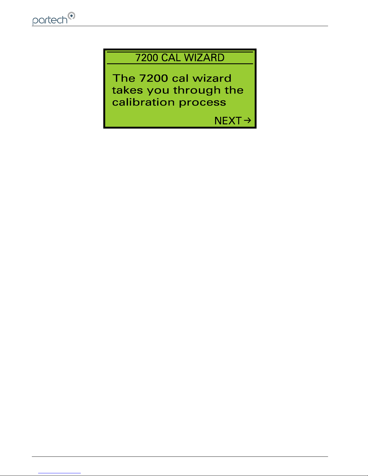
The 7200 calibration wizard guides the user through the important process of calibrating the instrument. When the
equipment is first installed, the setup wizard should be used to ensure that all the essential settings have been
properly set. Once the setup wizard has been completed, the instrument should respond to changes to the sensor
signal (for example placing the sensor into the zero solution and then into the calibration solution). Although the
instrument is responding, the factory default calibration values are used until user calibration is carried out.
Before using the calibration wizard, the guideline described in the preparation for calibration section above should be
observed.
Cal Wizard Keys
Once the calibration wizard has been entered, the MENU key can be used to exit at any time. Pressing the key
moves forward to the next step and pressing the moves back to the previous step. Pressing the OK key will activate
the displayed activity.
Cal Wizard Stages
The Cal Wizard guides the user through the process of setting the instrument zero and span. For more information
about setting zero and span, refer to the applicable section of this manual.
8.5 Set Zero
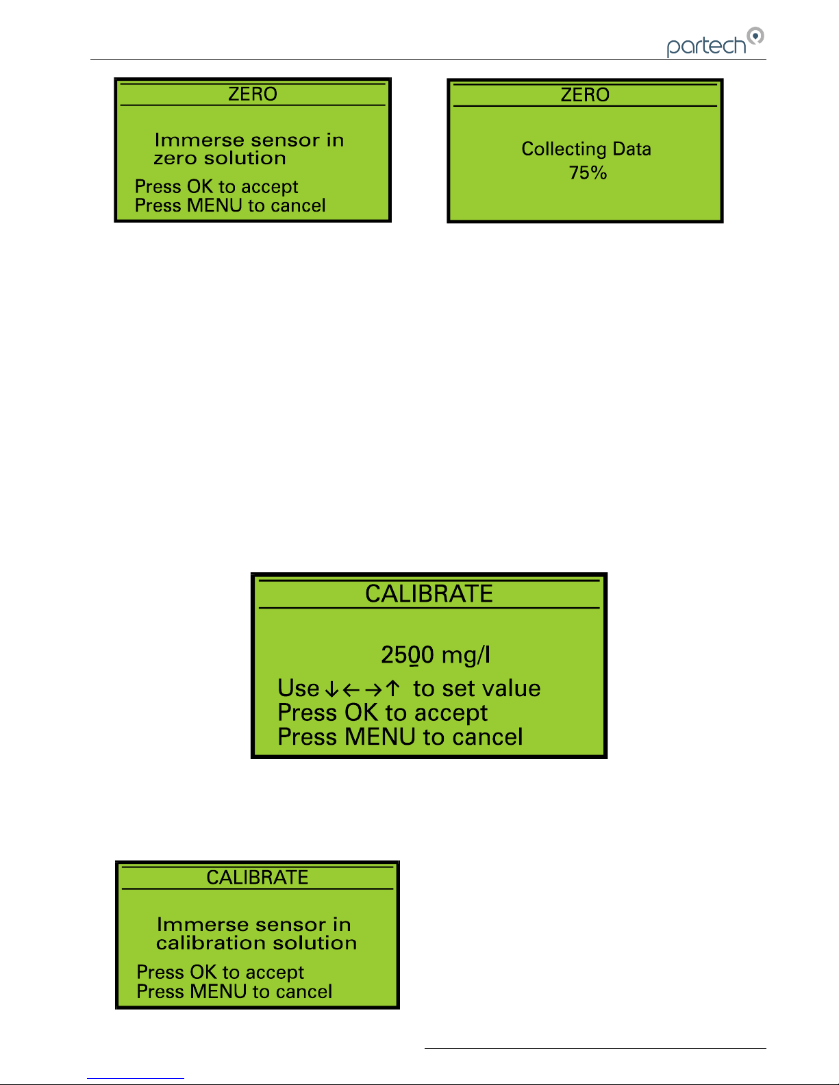
This menu is used to set the instrument display zero for the attached sensor. To zero the instrument, go to the
Calibration menu, select Set Zero and press the OK key. Immerse the sensor into the zero solution and press the OK
key. The 7200 Monitor collects data for the zeroing operation for approximately 5 seconds to ensure that the zero is
set accurately. During this period do not move the sensor, as this could effect the zero operation. If the zeroing
process is successful, the monitor will return to measure mode and the display value will be zero. If a problem occurs
during the zeroing operation, an error message will be displayed and the monitor will return to the Calibration menu.
Page 18 of 50 167300IM-Issue 12 Issue Date 14/10/2014
Calibration Wizard
Page 19
7200 Monitor Instruction Manual
8.6 Set Span
The Set Span function is used to set the calibration point for the instrument, which is used in the calculation of the
displayed value. To calibrate the instrument, go to the Calibration menu, select Set Span and press the OK key.
Note: If an online calibration is being carried out, whilst in measure mode check that the display value is
stable – it may be necessary to increase the damping level top stabilise the display value.
Step 1. Calibration Value Entry
The calibration value can be set to a value between 10 – 100% of the currently selected measuring range using the
keys. This value should be set to the value of the calibration solution. Once the correct value has been set
press the OK key. Pressing the MENU key will exit the Set Span operation.
Note: The calibration value can only be set between 10 –100% of the display range.
Step 2. Calibrating
As indicated by the on display instructions, immerse the sensor into the calibration solution and press the OK key. The
7200 Monitor collects data for the spanning operation for
approximately 5 seconds to ensure that the span is set
accurately. During this period do not move the sensor, as
this could effect the span operation. If the spanning
process is successful, the monitor will return to measure
mode and the display value should be correct for the
calibration solution. If a problem occurs during the
spanning operation, an error message will be displayed
and the monitor will return to the Calibration menu.
167300IM-Issue 12 Issue Date 14/10/2014 Page 19 of 50
Zero – Collecting Data
Zero - Preparation
Set Span –Calibration Value Entry
Set Span - Preparation
Page 20

7200 Monitor Instruction Manual
8.7 Take Sample
The Take Sample and Enter Sample Result facilities are
provided to allow calibration to be carried out
retrospectively based upon stored information. An
example of this is where the value of the calibration
solution is not known at the time of calibration and an
estimated value was used to set the instrument span.
The take sample menu is used to store the sensor
signal in the calibration solution for later use.
From the Calibration menu, select Take Sample and press the OK key. With the sensors immersed in the calibration
solution, (The display value must be stable – this can be checked when in measure mode) press the OK key. The
7200 Monitor collects data for the take sample operation for approximately 5 seconds; during this period do not move
the sensor. If the take sample process is successful, the monitor will return to measure mode. If a problem occurs
during the zeroing operation, an error message will be displayed and the monitor will return to the Calibration menu.
8.8 Enter sample Result
When the take sample operation has been carried out, and the correct value for the calibration solution is known, the
new calibration value can be entered using the Enter Sample Result menu.
To enter the new calibration value, from the calibration menu, select the Enter Sample Result menu and press the OK
key. The calibration value can be set to a value between 10 – 100% of the currently selected measuring range using
the keys. This value should be set to the value of the calibration solution. Once the correct value has been set
press the OK key. Pressing the MENU key will exit the Set Span operation.
Note: The calibration value can only be set between 10 –100% of the display range.
Page 20 of 50 167300IM-Issue 12 Issue Date 14/10/2014
Set Span – Data Collection
Page 21
7200 Monitor Instruction Manual
9 Setup Wizard
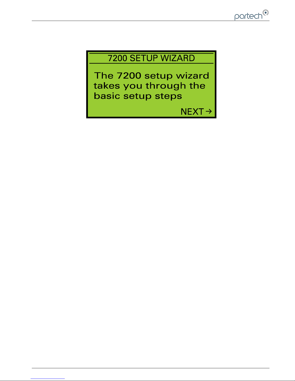
The 7200 setup wizard simplifies the process of setting up the instrument when first installed by guiding the user
through the basic (but important!) configuration steps. Prior to using the setup wizard, the following information should
be obtained:
Sensor Type Required measuring range
Title of measurement Measurement units
Type and Value of alarms Type and Range of analogue
output
Setup Wizard Keys
Once the setup wizard has been entered, the MENU key can be used to exit at any time. Pressing the key moves
forward to the next step and pressing the moves back to the previous step. Pressing the OK key will activate the
displayed activity.
Setup Wizard Stages
The Setup Wizard guides the user through the configuration of the following items, for more information about the
item, refer to the applicable section of this manual.
1. Sensor Type
2. Measurement Title
3. Units
4. Measurement Range
5. Alarm 1 Type
6. Alarm 1 Value
7. Alarm 2 Type
8. Alarm 2 Value
9. Output Type
10. Output Low Value
11. Output High Value
167300IM-Issue 12 Issue Date 14/10/2014 Page 21 of 50
Setup Wizard
Page 22

7200 Monitor Instruction Manual
10 Alarm outputs
The 7200 Monitor has two alarm outputs designated Alarm 1 and Alarm 2. Each alarm has a single pole changeover
output that signals the alarm condition. During normal operation when the alarm is not active the alarm output will be in
its NORMAL condition, the N/O (normally open) contact will be open and the N/C (normally closed) contact will be
closed. When the alarm is active the alarm output will be in its ALARM condition and therefore the N/O contact will be
closed and the N/C contact will be open.
Note: The alarm output will enter its ALARM condition if the power to the instrument is disconnected.
The alarms are identical and therefore the configuration procedure is the same for each and is carried out as
described in the following sections:
10.1 Alarm Value
The alarm value can be set to any value within the currently selected measuring range (Sensor Menu). The value can
be set using the keys, press OK to accept the new value or MENU to cancel and exit.
Note: The value can only be set within the range of the selected sensor range.
10.2 Alarm Type
The alarm type can be selected from the following:
Off
If the alarm is set to OFF, the output will remain in its NORMAL condition whilst the instrument is switched on
regardless of the measured value and other alarm settings.
Low
The output will go into the ALARM condition whenever the measured value is less than or equal to the alarm value.
The output will return to its NORMAL condition when the measured value is greater than the alarm value.
High
The output will go into the ALARM condition whenever the measured value is greater than or equal to the alarm value.
The output will return to its NORMAL condition when the measured value is less than the alarm value.
Fault
When the alarm type is set to fault, the alarm output will enter the ALARM condition when any of the selected faults
occur. The output will return to its NORMAL condition when all the selected faults are not active.
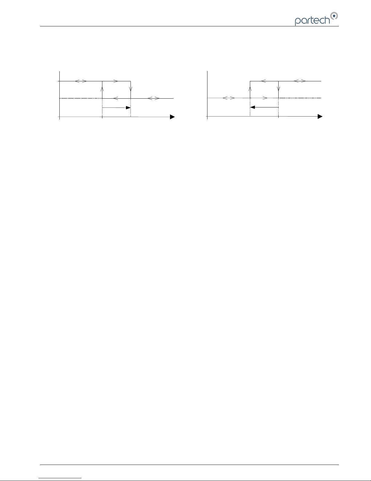
10.3 Alarm Hysteresis
In a normal condition an alarm turns on and off at the same value. For example, if a high alarm turns on at 2000mg/l
the alarm occurs when the reading increases to 2000mg/l. When it decreases through 2000mg/l the alarm turns off.
Some applications may demand that the alarm turns off at a different value, for a high alarm this would be value lower
than the alarm value, and for a low alarm this would be a value higher than the alarm value.
The hysteresis value determines the difference between the alarm switch on point and the alarm switch off point. In
the case of a high alarm, hysteresis causes the alarm to turn off at a value that is less than the alarm value. For a low
alarm, hysteresis causes the alarm to turn off at a value greater than the alarm value.
Page 22 of 50 167300IM-Issue 12 Issue Date 14/10/2014
Page 23
7200 Monitor Instruction Manual
The alarm hysteresis value can be adjusted between 0 – 10% of the selected display range using the keys.
Pressing OK key will enter the new value, pressing the MENU key cancels any changes made and exits from the
hysteresis set up.
10.4 Fault Alarm Setup
When the alarm type is set to fault, the alarm fault setup determines which faults the alarm output will signal (at least
one fault must be selected for the alarm output to work).
The faults that can be signalled by the alarm are displayed as a list, the enabled faults are indicated by small ticks. To
enable a fault, use the keys to highlight the required fault and press the OK key. A small tick will appear next to the
selected fault. To disable a fault, use the keys to select it and press the OK key, the small tick will disappear.
Note: The instrument faults are defined elsewhere within this manual.
10.5 Delay to Set
A delay can be introduced between conditions for an alarm turning on being met and the alarm actually turning on. At
any time during a delay, if the conditions for turning the alarm on disappear, then the delay will end and the alarm will
remain off (no change). The delay to set can be varied between 0-600 seconds using the keys. Pressing OK
will store the new value.
10.6 Delay to Reset
A delay can be introduced between conditions for an alarm turning off being met and the alarm actually turning off.
Such a delay can be varied between 0-600 seconds. At any time during a delay, if the conditions for turning the alarm
off disappear, then the delay will end and the alarm will remain on (no change).
10.7 Test Alarm Output
This facility enables the alarm output to be tested to enable verification of its operation and also to check that
equipment connected to it is working properly. By using the keys the alarm output can be toggled between its
NORMAL (OFF) and ALARM (ON) conditions. Press the OK or MENU key to exit.
10.8 Alarm Test Cycle
The alarm test cycle can be used when installing and configuring remote equipment on the alarm output. The alarm
output is automatically toggled between its NORMAL (OFF) and ALARM (ON) conditions every fifteen seconds and
will continue to do so for fifteen minutes after which the instrument will return to the measure mode. To exit the alarm
test cycle, press the OK or MENU key.
167300IM-Issue 12 Issue Date 14/10/2014 Page 23 of 50
Off
On
Alarm
Hysteresis
Alarm Value
Measured Value
Low Alarm with hysteresis
Off
On
Alarm
Hysteresis
Alarm Value
Measured Value
High Alarm with hysteresis
Page 24
7200 Monitor Instruction Manual
11 Analogue Output
The following section describes the setting up of the analogue output. The analogue output has three modes of
operation as shown in the table below:
Output Type Low High
4 – 20 mA 4 mA 20 mA
0 – 20 mA 0 mA 20 mA
0 – 5 V 0 V 5 V
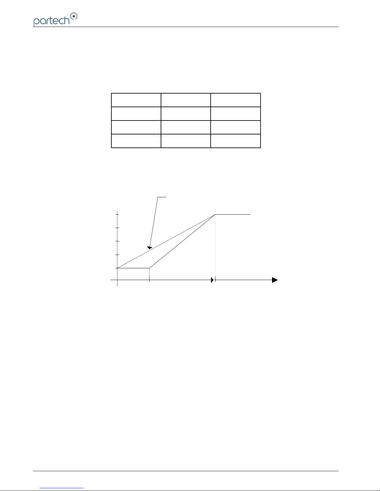
The output can be set to work over the whole of selected measurement range or a portion of it by the setting of the
output low and high values. It is also possible to configure the output to work reverse to normal, i.e. a 4 – 20 mA output
where 20 mA corresponds to the zero display value and 4 mA corresponding to the full scale value.
11.1 Set Output Low
Use the keys to set the required measurement value to produce the output low signal. Press OK to accept the
new value or MENU to cancel the new value.
Note: The value can only be set within the range of the selected sensor range.
11.2 Set Output High
Use the keys to set the required measurement value to produce the output high signal. Press OK to accept the
new value or MENU to cancel the new value.
Note: The value can only be set within the range of the selected sensor range.
11.3 Select Output Type
On entering the output type menu the current setting is indicated by a tick. Use the keys to move the select bar to
the required output type. Press the OK key to make the selection, a tick will appear against the selection. Press the
menu key to exit the output type menu.
Page 24 of 50 167300IM-Issue 12 Issue Date 14/10/2014
0
48121620
4 mA Value
e.g. 1000mg/l
20 mA Value
e.g. 3000mg/l
Measured Value
Current Output (mA)
This Line shows how a
normal 4-20mA output
works; going from 0.
Example output configuration (4-20mA)
Page 25

7200 Monitor Instruction Manual
11.4 Fault Output Mode
When any of the fault conditions occur, the output can be configured to go to one of three values, two of which can be
used to remotely detect the instrument fault.
Last Valid Measurement: The output will be held at the last value that was measured before the fault occurred and will
remain held until the fault is cleared.
High/Low Value: During a fault condition the output will go to its high or low value as indicated in the table above for
the selected output type.
On entering the fault condition output menu the present setting is indicated by a tick. Use the keys to move the
select bar to the required fault output. Press the OK key to make the selection, a tick will appear against the selection.
Press the menu key to exit the output type menu.
11.5 Fault Output Setup
The fault output setup determines which faults will cause the analogue output to enter its fault mode. If a fault occurs
that is not enabled, the output will remain at its last value until that fault has cleared.
The faults that can be signalled by the analogue output are displayed as a list; the enabled faults are indicated by
small ticks. To enable a fault, use the keys to highlight the required fault and press the OK key. A small tick will
appear next to the selected fault. To disable a fault, use the keys to select it and press the OK key, the small tick
will disappear.
Note: The instrument faults are defined elsewhere within this manual.
11.6 Test Output
This facility enables the analogue output to be tested to enable verification of its operation and also to check that
equipment connected to it is working properly. By using the keys the output signal can be increased/decreased
over its working range in fixed steps. Press the OK or MENU to exit.
11.7 Output Test Cycle
The output test cycle can be used when installing and configuring remote equipment on the analogue output. The
analogue output is automatically swept from its low to high value enabling the operator to view the result on the remote
equipment. The output is swept for fifteen minutes after which the instrument will return to the measure mode. To exit
the output test cycle, press the OK or MENU key.
167300IM-Issue 12 Issue Date 14/10/2014 Page 25 of 50
Page 26

7200 Monitor Instruction Manual
12 Sensor Configuration
Page 26 of 50 167300IM-Issue 12 Issue Date 14/10/2014
Page 27
7200 Monitor Instruction Manual
The 7200 Monitor can be used with several different Partech sensors, further details of each type can be found in the
relevant instruction manual.
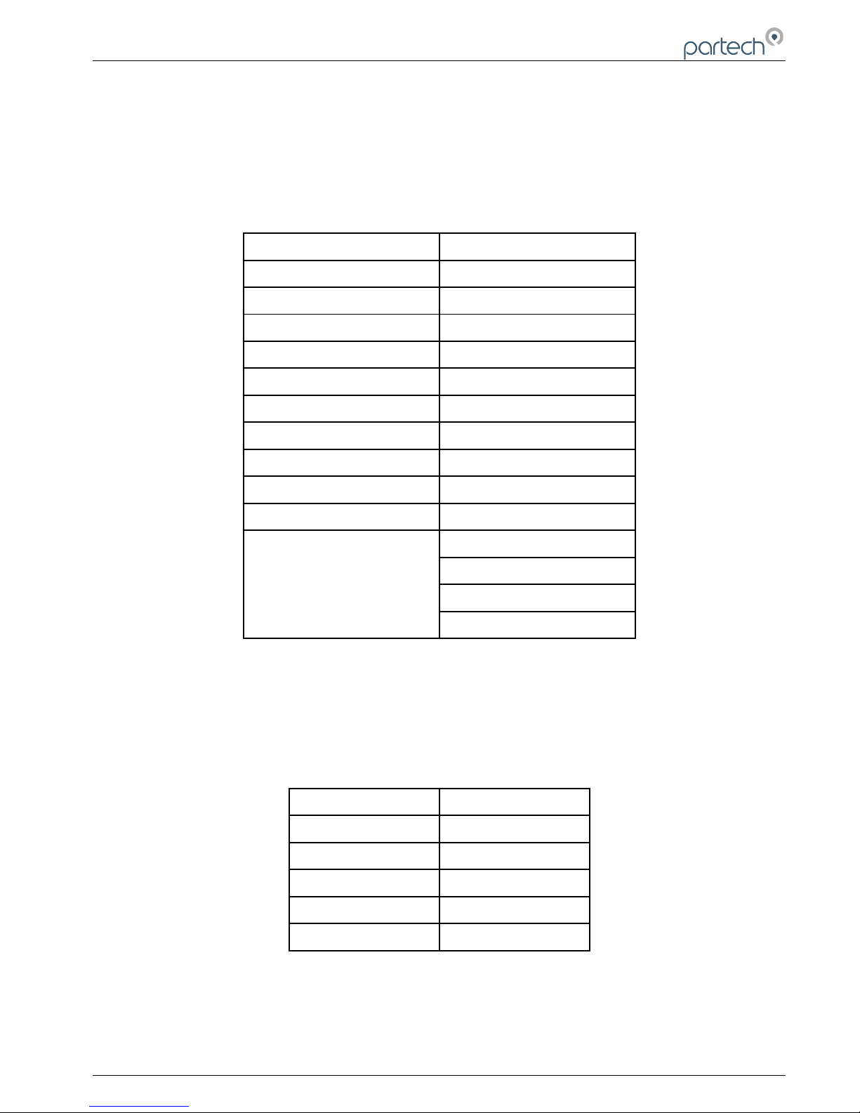
12.1 Select Sensor Type
The sensors that can be configured for use with the 7200 Monitor are displayed as a list, a small tick indicates the
currently selected sensor type. To select a different sensor type, use the keys to highlight the required sensor and
press the OK key. A small tick will appear next to the required sensor type. Press the MENU key to exit the sensor
type selection menu.
Sensor Types Sensor Range (typical)
IR8 0 – 20000 mg/l
IR15 0 – 10000 mg/l
IR40 0 – 1500 mg/l
IR100 0 – 200 mg/l
IR12LS 0 – 500 FTU
TT2000LA 0 – 20000 mg/l
TT2000LS 0 – 500 mg/l
TT10i/20i 0 – 20000 mg/l
TT2i/12i 0 - 500 mg/l
IL55/IL55BV2 0 – 5% SS
ST20
0 – 200mg/l
0 – 1500mg/l
0 – 10000mg/l
0 – 30000mg/l
NOTE: When the sensor type is changed, the sensor defaults for the new sensor are loaded and will over write
any settings that have been made with the previous sensor.
12.2 Select Display Range
The display range setting determines the range and resolution of the displayed measured value, a default range is
loaded when the sensor type is changed.
Range Resolution
0 – 10.00 0.01
0 – 100.0 0.1
0 – 1000 1
0 – 10000 10
0 – 50000 100
167300IM-Issue 12 Issue Date 14/10/2014 Page 27 of 50
Page 28
7200 Monitor Instruction Manual
12.3 Set Damping Rate
The 7200 Monitor has the ability to apply damping to the incoming sensor signal such that a stable measurement
value can be displayed. This is essential in applications where the effluent being monitored produces a fast varying
sensor signal such as in an aeration process.
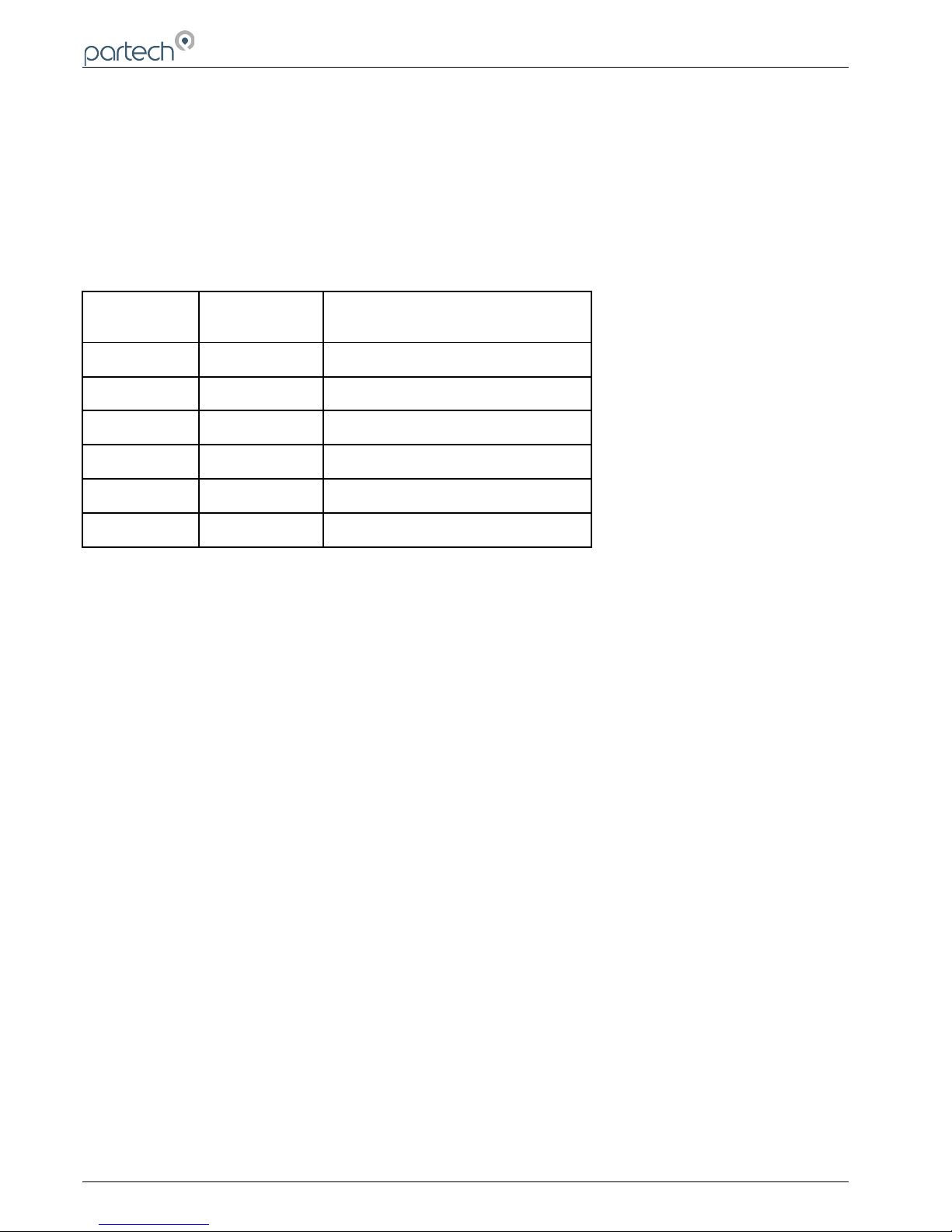
The response time quoted for each damping rate is indication of the monitor’s performance when a step change of 0 to
100% occurs on the sensor input. This can be useful when selecting the damping rate to be used for a particular
application.
Damping Rate Response Time
(Seconds)
Typical Use
Instant 0.2 Instrument Demonstration
Very Fast 1
Fast 10 Final Effluent
Medium 30
Slow 60 Aeration Lane
Very Slow 120
12.4 Air Clean Option
If the 7200 Monitor is being used with a Partech Air Clean System, this menu is used to enable the air clean function.
Selecting yes will enable air clean operation and the air clean setup menu will be displayed on the Instrument Config
menu.
Page 28 of 50 167300IM-Issue 12 Issue Date 14/10/2014
Page 29

7200 Monitor Instruction Manual
13 Advanced Sensor Setup
The advanced sensor menu allows the user adjustment of important sensor related settings. These settings can have
a major impact on the operation/configuration of the instrument and should only be altered by experienced users or
under the supervision of Partech.
Select Equation
This is used to determine the type of equation used to determine the measured value, only certain equations can be
used for each type of sensor.
Adjust Exp Constants
These values are used to perform linearisation on certain sensor types. The default values have been determined
through extensive testing and should produce acceptable results in most applications. If the linearity of the system is
not acceptable, please contact Partech technical support.
Adjust X Values
These values along with the Y values are used to perform linearisation on certain sensor types by means of a lookup
table. The X values represent the input values to the table and the Y values are used to determine the linear output
values. For further information on the use of lookup table linearisation please contact Partech.
Adjust Y Values
See Adjust X values above.
Sensor Defaults
It is sometimes necessary to restore the default values for the selected sensor type such that the instrument is in a
known state. To load the sensor defaults, select Sensor Defaults and press OK. To prevent accidental use, the user
password must be entered prior to confirming the operation.
167300IM-Issue 12 Issue Date 14/10/2014 Page 29 of 50
Page 30
7200 Monitor Instruction Manual
14 Instrument Setup
14.1 Measurement Title
This menu is used to select the measurement title displayed in measure mode. The user can select from a list of
predefined titles or enter a custom title. To select a measurement title, use the keys to highlight the required title
and press the OK key. If a predefined title is selected, a small tick will appear next to the selected title. If the userdefined option is selected, a new screen will be displayed which allows editing of the user defined title.
User Defined Title
To edit the user defined title, use the keys to select a character, and the keys to change the selected
character. When all changes are complete press the OK key to store the measurement title. To exit without saving
changes press the MENU key.
14.2 Display Units
The measurement units displayed in measure mode can be selected using this menu such that they are appropriate
for the measurement being made. The user can select units from a predefined list, enter custom units (user defined) or
switch off the display of units.
To select the measurement units, use the keys to highlight the required title and press the OK key. If a predefined
title is selected, a small tick will appear next to the selected title. If the user-defined option is selected, a new screen
will be displayed which allows editing of the user defined units.
User Defined Units
To edit the user defined units, use the keys to select a character, and the keys to change the selected
character. When all changes are complete press the OK key to store the new units. To exit without saving changes
press the MENU key.
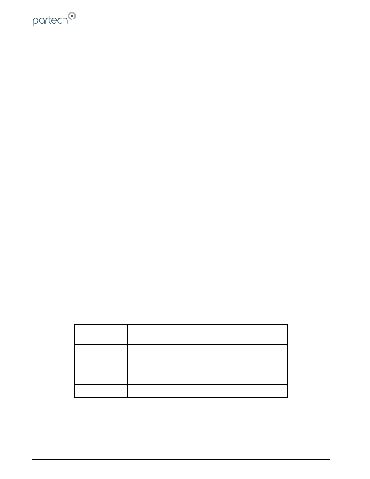
Linked Units
The m/g and g/l units are linked such that changing from one to the other will cause a change in the display range
such that the display value is appropriate for the units selected. The linked relationship between units and ranges is
shown in the table below.
Note: Changing from/to any units other than those shown will not effect the display range.
Old Range Old Units Units Changed
To:
New Range
0 – 10000 mg/l g/l 0 – 10.00
0 – 50000 mg/l g/l 0 – 100.0
0 – 10.00 g/l mg/l 0 – 10000
0 – 100.0 g/l mg/l 0 – 50000
14.3 Display Contrast
When this menu is selected, the display contrast can be adjusted over the range 0% (light) to 100% (dark) using the
keys. Pressing the OK key stores the new contrast setting and exits the menu, pressing the MENU key exits losing
any changes made to the contrast setting.
Page 30 of 50 167300IM-Issue 12 Issue Date 14/10/2014
Page 31

7200 Monitor Instruction Manual
14.4 Bleeper
This option allows the bleeper to be turned on or off, a small tick indicates the current setting. To change the bleeper
setting, use the keys to select the required setting and press OK. Press MENU to exit the bleeper menu.
14.5 Backlight
The backlight can be set to one of three modes, On, On after key press (the backlight stays on for 5 seconds after a
key is pressed) or Off. The current backlight mode is indicated by a small tick, to change the backlight mode, use the
keys to select the required mode and press OK. Press MENU to exit the backlight menu.
14.6 Language
This facility is used to select the operating language of the instrument and is configured using the list select method of
data entry.
14.7 Change Password
The user password used when the instrument is locked and unlocked can be adjusted using this menu. The first stage
in changing the password is to enter the existing password, which is done using the keys. Once the old
password has been entered, press the OK key to proceed to the next stage, which is the entry of the new password.
The new password can be entered using the keys and pressing the OK key will store the new password. At
any stage whilst the password is being changed, pressing the MENU key will exit the menu and the old password will
be unchanged.
Note: The factory default password is 1000, if the original password has been forgotten please contact
Partech technical support.
14.8 Reset Instrument
It is sometimes necessary to restore the default values for all the user configurable parameters such that the
instrument is in a known state. To load the user defaults, select Reset Instrument and press OK. To prevent accidental
use, the user password must be entered prior to confirming the operation.
167300IM-Issue 12 Issue Date 14/10/2014 Page 31 of 50
Page 32
7200 Monitor Instruction Manual
15 Clean Setup
The clean setup and manual clean menu’s are only display if the selected sensor type is capable of auto cleaning. If a
non self-cleaning sensor is being used, the following section is not applicable.
The Partech range of self cleaning sensors are designed such that the 7200 Monitor determines when a clean cycle is
performed. During a clean cycle, the 7200 Monitor display value, alarm outputs and analogue output are all frozen,
and are only unfrozen once the clean cycle is complete. The stage of the clean cycle is indicated on the measure
mode status bar throughout the clean cycle.
For further information regarding the clean operation of a self-clean sensor, please refer to the appropriate sensor
instruction manual.
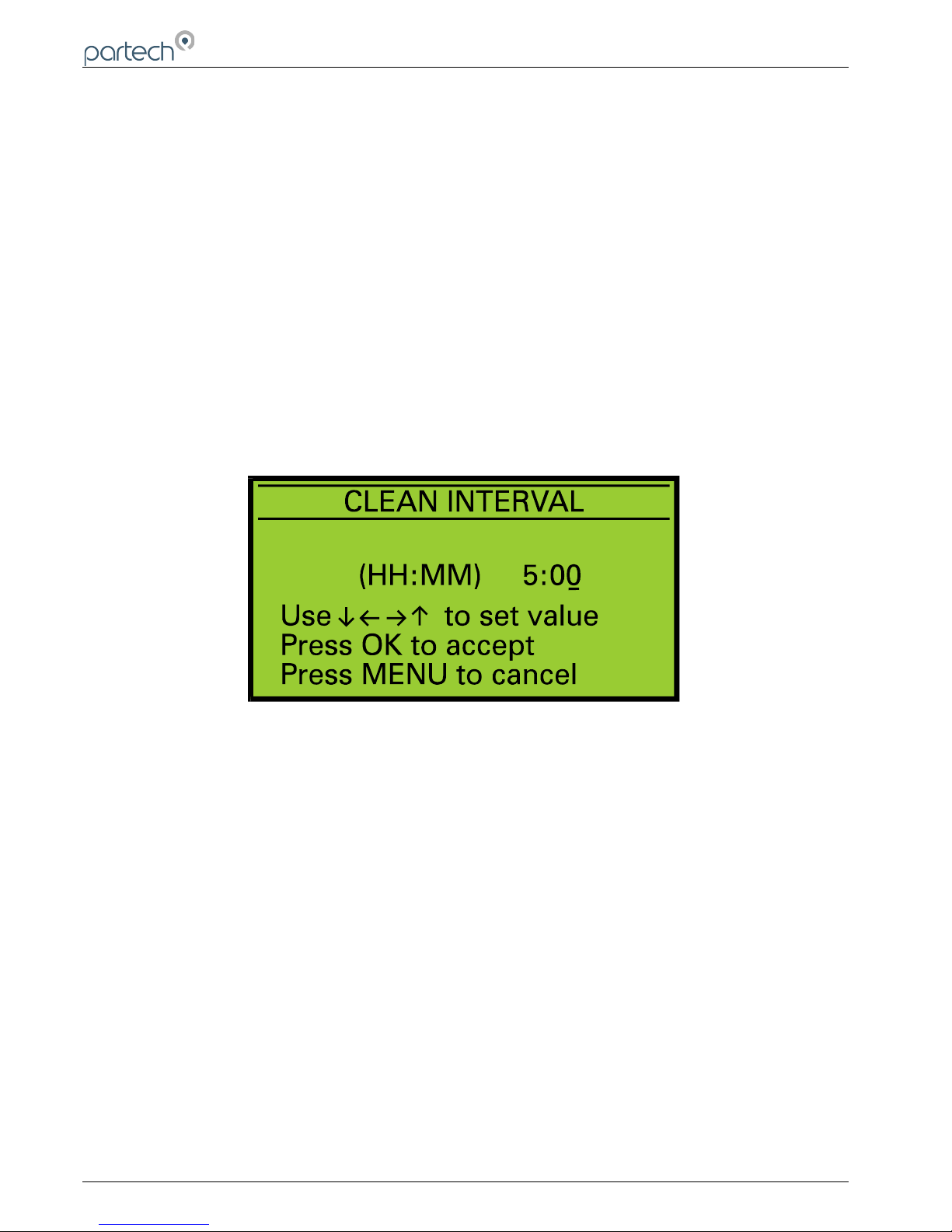
15.1 Set Clean Interval
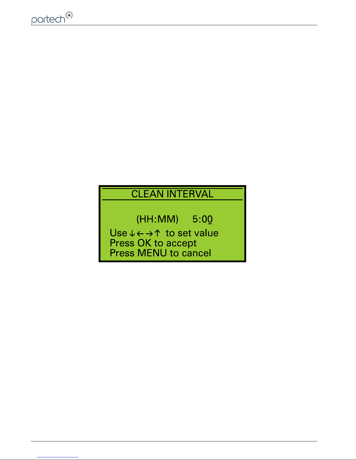
The clean interval determines the length of time between the sensor being cleaned. The user can select a clean
interval between 30 minutes and 24 hours, using the value adjustment method of data entry.
Note: The clean interval is entered in hours and minutes. (HH:MM)
15.2 Clean Mode
The clean mode menu is used to set whether the sensor will operate in its Normal or Reverse mode. The default
setting for clean mode is Normal and this is suitable for most applications.
Normal Mode
In this mode, the sensor is measuring most of the time with the sensor probes extended. The clean cycle causes the
retraction of the sensor probes into the sensor housing such that the probes are cleaned. The probes are then
extended back to the measuring position and measurement recommences.
Reverse Mode
When the sensor is used in reverse mode, the sensor probes are held in the fully retracted position for the majority of
time and a stored measurement is used for the display value, alarm and analogue outputs. The clean interval is used
to determine when the sensor probes are extended. Once fully extended a measurement is performed and the stored
value is updated. The sensor probes are then retracted to the fully in position.
Page 32 of 50 167300IM-Issue 12 Issue Date 14/10/2014
Clean Interval
Page 33
7200 Monitor Instruction Manual
15.3 Clean Information
This display provides general information regarding the sensor cleaning process.
Time until clean
This indicates the time until the next clean cycle in hours, minutes and seconds.
Clean Count
The clean count indicates the number of cleans that the sensor has performed since it was installed or last serviced,
and the set service life that has been set.
Service Due
Using the clean count and service life, the number of days until a service is required is calculated and displayed. This
is very useful in planning the servicing of a self-clean sensor.
15.4 Service Life
The service life is the number of cleans that the sensor can perform before requiring a service (replacement of wiper
and sealing rings etc.). The default value is 3500 cleans and this is suitable for most applications. However where the
application causes severe wear of the wiper and sealing rings, the service life should be reduced. When the service
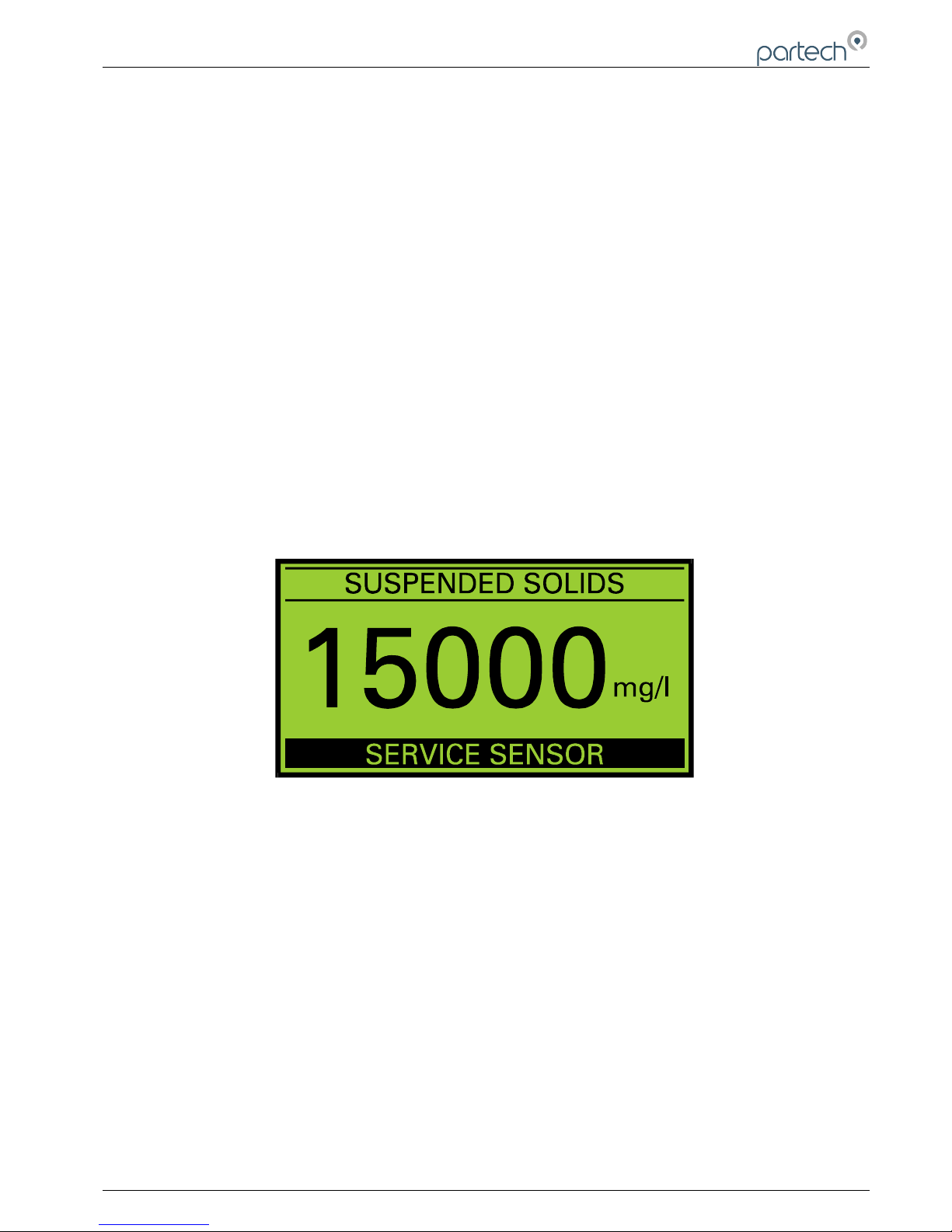
life has been reached a fault message indicating this is displayed in measure mode.
15.5 Reset Clean Count
When the sensor has been serviced, this menu can be used to reset (zero) the clean count and clear the service
sensor fault.
167300IM-Issue 12 Issue Date 14/10/2014 Page 33 of 50
Service Sensor Fault Message
Page 34
7200 Monitor Instruction Manual
16 Air Clean Setup
The air clean setup and manual air clean menu’s are only display if the air clean option has been enabled on the
sensor setup menu. The air clean option should only be enabled when the 7200 is being used with a Partech air clean
system. If an air clean system is not being used, the following section is not applicable.
Partech air clean systems are designed such that the 7200 Monitor controls when an air clean cycle is performed.
During an air clean, the 7200 Monitor display value, alarm outputs and analogue output are all frozen, and are only
unfrozen once the air clean is complete. During an air clean, a countdown of the remaining time is indicated on the
measure mode status bar.
For further information regarding the air clean system, please refer to the appropriate air clean system instruction
manual.
16.1 Set Clean Interval
The clean interval determines the length of time between the sensor being cleaned. The user can select a clean
interval between 30 minutes and 24 hours, using the value adjustment method of data entry.
Note: The clean interval is entered in hours and minutes. (HH:MM)
16.2 Clean Duration
The length of time that the air pump is running during a clean is set by the clean duration value. The clean duration
should be set to provide adequate cleaning of the sensor for the application in which it is being used.
16.3 Settling Time
The settling time determines the length of time after the air pump has stopped before the instrument returns to live
measurements. The purpose of the settling time is to ensure that the display value is not effected by bubbles or
turbulence caused by the cleaning process.
Page 34 of 50 167300IM-Issue 12 Issue Date 14/10/2014
Clean Interval
Page 35
7200 Monitor Instruction Manual
16.4 Clean Information
This display provides general information regarding the sensor cleaning process.
Time until clean
This indicates the time until the next clean cycle in hours, minutes and seconds.
Clean Count
The clean count indicates the number of air cleans that have been completed since the air pump was installed or last
serviced.
Run Time
The run time displays the accumulated length of time the air pump has been running.
16.5 Service Life
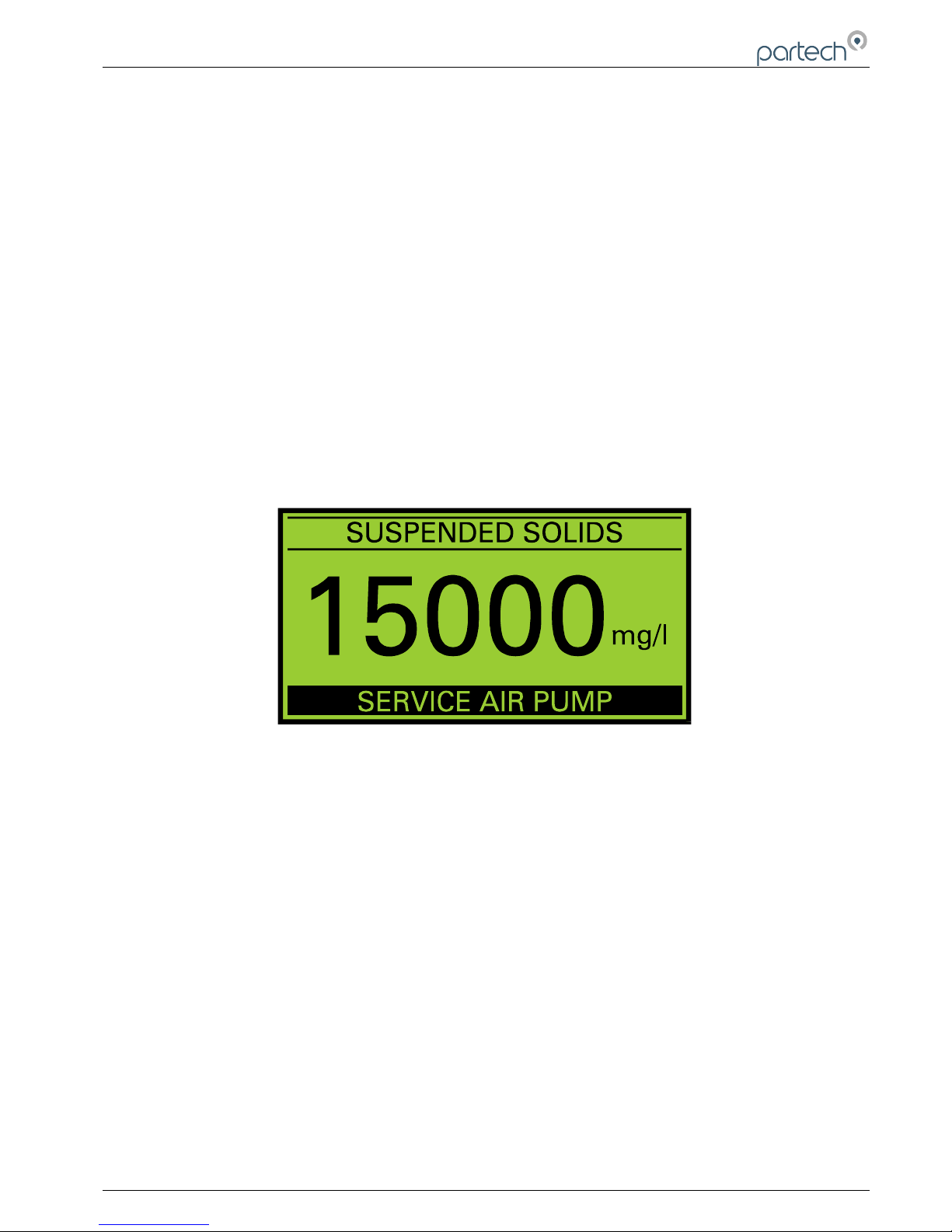
The service life is the number of hours that the pump can be used. When the service life has been reached a fault
message indicating this is displayed in measure mode.
16.6 Reset Clean Count
When the air pump has been serviced, this menu can be used to reset (zero) the air clean count and clear the service
air pump fault.
167300IM-Issue 12 Issue Date 14/10/2014 Page 35 of 50
Service Air Pump Fault Message
Page 36

7200 Monitor Instruction Manual
17 Diagnostics
The diagnostics menu provides information regarding the internal setup and operation of the instruments and is a very
useful facility in assisting problem diagnosis. If a problem has occurred, contact Partech technical support for
assistance.
17.1 Sensor Input
This display indicates the input signals from the sensor, U: is the raw signal from the sensor D: is the raw sensor
signal with damping applied, S: is the approximate supply current to the sensor, L: is an internally used version of the
damped sensor signal and M: is the display value.
17.2 Sensor %
This is a bar graph display of the undamped and damped sensor signals on a 0 to 100% scale, where 100% equates
to the sensors upper range value.
17.3 Calibration Values
This indicates the internal values used to store the calibration and sensor setup data.
17.4 Factory Values
These values are set during factory calibration of the unit.
17.5 Diagnostic Values
These are additional values that are helpful when diagnosing instrument problems.
17.6 Diagnostic Download
This facility allows the downloading of the calibration, factory and internal values using the RS232 serial interface.
17.7 Opto Inputs
This display indicates the status of the opto-input signals from self-cleaning sensors.
17.8 ADC Inputs
The analogue to digital converter input values can be viewed using this menu.
Page 36 of 50 167300IM-Issue 12 Issue Date 14/10/2014
Page 37

7200 Monitor Instruction Manual
18 Information
18.1 Statistics
View Statistics
The measurement statistics are updated continually when the instrument is operating and provide a useful indication
of how the application is varying. The statistics are reset when the instrument is powered up and are therefore only
valid from that point. The statistic values can be viewed using the View Statistics menu.
Set Average Period
The average period determines the length of time measurement data is collected for use in calculating the statistics
average value. The average period can be set in the range 10 to 100 seconds, and is adjusted using the keys.
Pressing the OK key stores the new setting.
Download Statistics
This facility allows the downloading of the statistic values using the RS232 serial interface.
Reset Statistics
The statistic values can be reset using this menu.
18.2 Software Version
This display indicates the software version and serial number of the instrument and is useful for recording and problem
diagnosis.
18.3 Contact Information
This display provides contact information for Partech (Electronics) Ltd.
167300IM-Issue 12 Issue Date 14/10/2014 Page 37 of 50
Page 38

7200 Monitor Instruction Manual
19 Instrument Security
The 7200 Monitor can be locked to prevent unauthorised access to the configuration menu’s by using a password. The
user password is a 4 digit number that can be set to any value the user chooses. When supplied new, the user
password is set to 1000, we recommend that this is changed when the instrument is installed.
Note: The factory default password is 1000, if the original password has been forgotten please contact
Partech technical support.
19.1 Lock Instrument
To lock the instrument, this menu is used. The user will be prompted for the entry of the user password, when entered
correctly the instrument will be locked. The instrument can only be locked with the correct user password thus avoiding
accidental/unauthorised locking.
19.2 Change Password
The method of changing the user password is described in the instrument configuration section of this manual.
Page 38 of 50 167300IM-Issue 12 Issue Date 14/10/2014
Page 39

7200 Monitor Instruction Manual
20 Error Messages
When the instrument detects an error condition, an error message will be displayed. All the error messages are
described below. Certain error/fault conditions can be used in the fault setup of the alarms and analogue output and
are identified by a *.
20.1 Sensor
No Sensor *
No sensor detected on input to monitor if sensor is connected and wiring is okay either sensor fault or monitor fault.
Sensor Low Limit *
Sensor input signal is too low possible, sensor fault.
Sensor High Limit *
Sensor input signal is too high possible, sensor fault.
20.2 Measure Mode
Display Over Range *
Calculated display value greater than selected display range maximum, either change display range or check
calibration is correct.
Display Under Range *
Calculated display value is less than selected display range minimum, check calibration.
20.3 Self Clean Sensors
Clean Fault *
During a clean cycle the sensor detected a fault. Inspect sensor for damage and/or excess fouling – if there is no
evidence of this remove and reapply power to the monitor and observe the clean operation.
Clean Time Out *
The clean cycle took too long to complete. Inspect sensor for damage and/or excess fouling – if there is no evidence
of this remove and reapply power to the monitor and observe the clean operation.
Service Sensor *
Sensor requires servicing (clean count is greater than service life). Service sensor then use reset clean count to zero
clean count and clear the service sensor fault.
Std Error *
The standardise sensor reading is outside of the allowed limits. Check sensor for excess fouling, scratched/damaged
glass tubes or other damage. If nothing is found remove and reapply power to the monitor and use manual clean to
activate a clean cycle. If the fault reoccurs, contact Partech technical support for assistance.
167300IM-Issue 12 Issue Date 14/10/2014 Page 39 of 50
Page 40

7200 Monitor Instruction Manual
20.4 Calibration
Not Available - Sensor Fault
If one of the above sensor faults is present, it is not possible to perform a calibration. Clear the sensor fault and try
again.
Sensor Input Too High (Set Zero)
The data collected for the zero operation was above the allowed maximum for a zero operation. This can be caused
by a dirty zero solution, fouling on the sensor or a fault with the sensor.
Sensor Input Too Low (Set Zero)
The data collected for the zero operation was below the allowed minimum for a zero operation. This generally
indicates that the sensor is faulty.
Sensor Input Too Low (Set Span)
The data collected for the calibration operation was below the allowed minimum for the span to be set. This occurs
when sensor signal in the calibration solution is too close to the sensor signal in the zero solution. This can be caused
by a too clear calibration solution, the wrong sensor type or a fault with the sensor.
20.5 Air Clean Systems
Service Air Pump *
The air clean pump requires servicing (pump run hours are greater than service life). Service the air pump then use
reset clean count to zero pump run time and clear service sensor fault.
Page 40 of 50 167300IM-Issue 12 Issue Date 14/10/2014
Page 41

7200 Monitor Instruction Manual
21 Menu Structure
Manual Clean*
Calibration
Calibration Wizard
Set Zero
Set Span
Take Sample
Enter Sample Result
Instrument Configuration
Setup Wizard
Alarm 1 Setup
Set Alarm Value
Alarm Type
Alarm Hysterisis
Fault Alarm Setup
Delay To Set
Delay To Reset
Test Alarm
Cycle Alarm
Alarm 2 Setup
Alarm Value
Alarm Type
Alarm Hysterisis
Fault Alarm Setup
Delay To Set
Delay To Reset
Test Alarm
Cycle Alarm
Output Setup
Set Output Low
Set Output High
Select Output Type
Fault Output Mode
Fault Output Setup
Test Output
Cycle Output
Sensor Setup
Select Sensor Type
Set Display Range
Set Damping Rate
Air Clean Option
Advanced Menu
Select Equation
Adjust Exp Constants
Adjust X Values
Adjust Y Values
Sensor Defaults
Clean Setup*
Clean Interval
Clean Mode
Clean Information
Service Life
Reset Clean Count
Air Clean Setup**
Clean Interval
Clean Duration
Settling Time
Service Life
Clean Information
Reset Clean Count
Instrument Setup
Measurement Title
Display Units
Display Contrast
Bleeper
Backlight
Language
Change Password
Reset Instrument
Diagnostics
Sensor Input
Sensor %
Up Time
Calibration Values
Factory Values
Diagnostic Values
Diagnostic Download
Opto Inputs
ADC Inputs
Information
Statistics
View Statistics
Set Average Period
Download Statistics
Reset Statistics
Software Version
Contact Information
Website Address
Email Address
Lock Instrument
* Only visible/selectable when a self cleaning sensor type is selected
** Only visible when the air clean option is enabled.
167300IM-Issue 12 Issue Date 14/10/2014 Page 41 of 50
Page 42
7200 Monitor Instruction Manual
22 Sensor Defaults
The sensor default values are shown in the table below:
Sensor Type Calibration Value Display Range Units Equation
IR8 20 0 – 100.0 mg/l Exp
IR15 10000 0 – 10000 mg/l Exp
IR40 1500 0 – 10000 mg/l Exp
IR100 200 0 – 1000 mg/l Exp
IR12LS 500 0 – 1000 FTU Lin
TT2000LA 10000 0 – 50000 mg/l Exp
TT2000LS 500 0 – 1000 mg/l Lin
TT10i/20i 10000 0 – 50000 mg/l Exp
TT2i/12i 500 0 – 1000 mg/l Lin
IL55/IL55BV2 50 0 – 100.0 % SS Lin
ST20
200 0 - 1000 mg/l Exp
1500 0 - 10000 mg/l Exp
10000 0 - 10000 mg/l Exp
20 0 - 50000 mg/l Exp
Page 42 of 50 167300IM-Issue 12 Issue Date 14/10/2014
0-200
0-1500
0-10000
0-30000
Page 43

7200 Monitor Instruction Manual
23 Preparation of Fullers Earth Solution
The Fuller's Earth is supplied in a sealed 20g package, the package contains sufficient to make a 20,000 mg/l (20 g/l)
solution when combined with 1 litre of water. Alternate solutions can be obtained by increasing the amount of water
used as shown in the table below.
Solution Required (g/l)
Add pack to water
(litres)
2.5 8.0
5.0 4.0
10.0 2.0
20.0 1.0
40.0 0.5
The following points should be observed when preparing and using Fullers Earth solutions:
• The water used should be freshly distilled or de-mineralised
• Ensure the container used for the solution is clean
• During preparation and use, keep the solution covered to prevent contamination
• When using the solution it must be continually stirred to ensure accurate and consistent measurements and to
prevent settling
167300IM-Issue 12 Issue Date 14/10/2014 Page 43 of 50
Page 44

7200 Monitor Instruction Manual
24 Preparation of Formazin Turbidity Standardise
Health & Safety Precautions
The chemicals used when following this procedure are harmful, therefore the correct safety precautions must be
carried out. During handling, avoid inhalation and contact with the eyes or skin. Wash hands thoroughly after use.
Refer to the data sheets for further details of the chemicals used.
Method of Preparation
The preparation of a Formazin Turbidity Standard should be carried out with great care. Absolute cleanliness should
be observed at all times to avoid any contamination of the solution.
All water used should be freshly distilled or de-mineralised. During preparation and use, keep the solution covered to
prevent contamination.
1. Dissolve the Hydrazinium Sulphate 10g (32112680) into 1 litre of water. Stir the solution thoroughly.
2. Dissolve the Hexamine 100g (32112630) into 1 litre of water. Stir the solution thoroughly.
3. Pour the above solutions into a 2.5 litre Winchester or similar type amber glass bottle and mix thoroughly. Allow the
mixture to stand undisturbed for 24 hours at 25°C. The resultant solution will have a turbidity of 4000 FTU.
4. Prior to use the standard should be mixed thoroughly. i.e. before pouring out the standard, shake the bottle well.
Preparation of Dilution’s.
The 4000 FTU standard can be used to prepare solutions of lower values by diluting with water. The formula below
can be used to calculate the ratio of water to 4000 FTU standard to produce a solution of the required value.
W
A
= −
4000
1
W = parts water to 1 part 4000 FTU standard
A = Required FTU value
The Formazin Dilution Chart provides the mixture requirements to make various solutions using the 4000 FTU
standard.
Calibration
When Formazin solutions are used for calibration/testing of sensors, sufficient solution is required such that the sensor
is completely immersed. When using light scatter sensors it is important that the sensor is positioned away from the
sides and bottom of the container to prevent the light being reflected.
Storage Life
The turbidity standard should be stored in the Winchester bottle and kept in a cool dark place. The bottle should be
labelled to identify its content and also the date of preparation should be recorded. The 4000 FTU standard has a shelf
life of one year after which it should be discarded and a fresh solution should be prepared.
Solutions made by diluting the 4000 FTU standard should also be stored in suitably labelled amber glass bottles and
kept in a cool dark place. Solutions above 400 FTU have a shelf life of one month after which they should be
discarded. Solutions below 400 FTU should be prepared from the 4000 FTU standard daily.
Solutions can be used outside of the storage lives specified above but any results taken must acknowledge this and
be accepted as less accurate. When using solutions, watch for flocculation (the particles in the solution will appear to
link together), if this occurs discard the solution and prepare a fresh standard.
Page 44 of 50 167300IM-Issue 12 Issue Date 14/10/2014
Page 45

7200 Monitor Instruction Manual
25 Technical Support
Technical Support is available by phone, fax, or email, the details of which are shown below.
• Phone: +44 (0) 1726 879800
• Fax: +44 (0) 1726 879801
• Email: techsupport@partech.co.uk
• Website: www.partech.co.uk
To enable us to provide quick and accurate technical support please have the following information ready when you
contact us:
• Serial Number or original purchase details
• Sensor Type, and Serial Number
• Application details
• Description of fault
25.1 Returning Equipment for Repair
If equipment needs to be returned to Partech for repair or service the following address should be used:
SERVICE DEPARTMENT
PARTECH INSTRUMENTS
ROCKHILL BUSINESS PARK
HIGHER BUGLE
ST AUSTELL
CORNWALL
PL26 8RA,
UK
Please include the following information with the returned equipment. Also ensure that sensors are adequately
protected for transportation (Advice on packing can be provided by our service department).
• Contact name and phone number
• Return address for equipment
• Description of fault or service required
• Any special safety precautions because of nature of application
167300IM-Issue 12 Issue Date 14/10/2014 Page 45 of 50
Page 46

7200 Monitor Instruction Manual
26 Technical Specification
26.1 General
Supply Voltage ............................... 85-264VAC, 50/60 Hz,
Power Consumption........................15 VA
Supply Fuse....................................1.6A Anti surge 20 x 5mm (Fitted Internally)
Operating Temperature...................0 to 50°C
Storage Temperature......................-20 to 70°C
Display Resolution..........................0.1%
Response Time...............................0.2 to 120 Seconds (User selectable)
Linearity...........................................(Refer to sensor specification)
Accuracy.........................................(Refer to sensor specification)
Repeatability...................................(Refer to sensor specification)
26.2 Alarm Outputs
Number of Outputs..........................2 SPCO
Alarm Types....................................Low, High, Fault (User configurable)
Operation........................................Fail Safe (De-energised in alarm condition)
Relay Rating....................................5 A @ 230 VAC, 5 A @ 30 VDC
26.3 Analogue Output
Type:...............................................4-20 mA/0-20 mA/0-5 V (User configurable)
Resolution:......................................Better than 0.5%
4-20mA Maximum Output Load:.....1000 Ohms
0-20mA Maximum Output Load:.....1000 Ohms
0-5V Minimum Output Load:...........1000 Ohms
26.4 EMC
EMC:...............................................EN 61000-6-1(2001) EN 61000-6-3(2001)
26.5 Field Mount
Dimensions:....................................160 × 166 × 73 mm (h × w × d)
Weight:............................................1 Kg
Environmental Rating:.....................IP65
Material:..........................................ABS
Cable Entry:....................................4 × PG11 (2 factory fitted, 2 supplied separately)
Terminals:.......................................Max conductor cross section 2.5 mm2
Page 46 of 50 167300IM-Issue 12 Issue Date 14/10/2014
Page 47

7200 Monitor Instruction Manual
27 Declaration of Conformity
DECLARATION OF CONFORMITY
According to EN 45014
We, Partech Instruments, Rockhill Business Park, Higher Bugle, St Austell, Cornwall, PL25
3NN, UK declare under our sole responsibility that the product:
Product Name: 7200 Monitor
Model Number(s): 167200
to which this declaration relates is in conformity with the standards noted below:
EN 61326:1998 -Electrical equipment for measurement, control, and laboratory use
—EMC requirements.
EN 61000-6-1:2001—Electromagnetic compatibility (EMC)—Part 6-1: Generic
standards—Immunity for residential, commercial, and light-industrial environments.
EN 61000-6-3:2001—Electromagnetic compatibility (EMC)—Part 6-3: Generic
standards—Emission standard for residential, commercial, and light-industrial
environments.
following the provisions of European Directives:
89/336/EEC Electromagnetic Compatibility Directive
92/31/EEC Amending 89/336/EEC
93/68/EEC Amending 89/336/EEC
73/23/EEC Low Voltage Directive
93/68/EEC Amending 73/23/EEC
Roger Henderson, Technical Director, February 21, 2006
167300IM-Issue 12 Issue Date 14/10/2014 Page 47 of 50
Page 48

7200 Monitor Instruction Manual
167300IM-Issue 12 Issue Date 14/10/2014 Page 48 of 50
Page 49

7200 Monitor Instruction Manual
167300IM-Issue 12 Issue Date 14/10/2014 Page 49 of 50
Page 50
Partech Instruments
Rockhill Business Park, Higher Bugle, St Austell, Cornwall, PL26 8RA, UK
Tel: +44(0)1726 879800
Email: [email protected] Web: www.partech.co.uk
 Loading...