

Page 1

INSTRUCTION REF: IN173
ISSUE No. 2
DATE 17.12.09
Page 1 of 16
INSTRUCTIONS
MODEL: PGC6
SAFETY INSTRUCTIONS
INSTALLATION INSTRUCTIONS
OPERATION INSTRUCTIONS
MAINTENANCE INSTRUCTIONS
CONVERSION INSTRUCTIONS
TECHNICAL DATA
PARTS LIST
SPARES LIST
WARRENTY INFORMATION
Customer Information
Unit Code:
Serial Number:
Purchase Date:
www.parry.co.uk
Page 2

INSTRUCTION REF: IN173
ISSUE No. 2
DATE 17.12.09
Page 2 of 16
SAFETY INSTRUCTIONS
IMPORTANT, PLEASE READ INSTRUCTIONS FULLY BEFORE USE
THIS APPLIANCE IS ONLY FOR PROFESSIONAL USE AND MUST ONLY BE
USED BY QUALIFIED PEOPLE.
Attention should be drawn to the fact that parts of this unit by necessity, will get
VERY HOT, and will cause burns if touched accidentally. Therefore it is the
responsibility of the supervisor or equivalent to provide SUITABLE PROTECTIVE
CLOTHING for the user.
THIS APPLIANCE MUST BE FITTED AND TESTED BY A REGISTERED
FITTER BEFORE USE.
The unit should be installed in compliance with the INSTALLATION
INSTRUCTIONS and the NATIONAL REGULATIONS in force at the time.
Particular attention should be paid to the Gas Safety (Installation and Use)
Regulations and the Health and Safety at Work Act.
Each appliance requires a flow of fresh air for combustion. Under no
circumstances should air vents on the appliances, or air vents installed by the
fitter in the room of the appliance to supply combustion air, be altered or omitted
in any way.
To prevent shocks, all appliances whether gas or electric, must be earthed.
ANY GAS CONVERSIONS NEEDED TO BE MADE TO THE PRODUCT MUST
BE CARRIED OUT BY A CORGI REGISTERED ENGINEER
To avoid scratching the highly polished exterior surface of this equipment whilst
in transit, the protective film on the exterior surfaces has NOT been removed.
It is IMPORTANT that this protective film is peeled off before the equipment is
used.
www.parry.co.uk
Page 3

INSTRUCTION REF: IN173
ISSUE No. 2
DATE 17.12.09
Page 3 of 16
MODEL
The products stated above are designed and built to comply with the following
standards:
BS EN 203-1:2005+A1 2008
BS EN 203-2-9:2005
The products have been CE-marked in compliance with the European Gas
Directive (90/396/EEC)
INSTALLATION INSTRUCTIONS
ALL APPLIANCES MUST BE FITTED AND OR CONVERTED BY A
REGISTERED INSTALLER, IN ACCORDANCE WITH CURRENT
REGULATIONS.
INSTALLATION
1. All appliances must not be installed on or against any combustible surface.
Clearances around appliances must be:
CEILING/SHELF 900mm
REAR 75mm
SIDES NIL
It should be noted that the sides of the appliance will get hot and
appliances with components sensitive to heat, should not be placed
directly next to the unit.
2. During installation provision must be provided for combustion air supply to
the appliance, which enters the appliance through the base and rear of the
appliance, this should not be blocked at any time. SEE TECHNICAL
DETAILS.
www.parry.co.uk
Page 4

INSTRUCTION REF: IN173
ISSUE No. 2
DATE 17.12.09
Page 4 of 16
3. Appliances are designed to be installed on Parry Catering Equipment for
stability, should they be fitted on any other surface they should be suitably
secured, to prevent excessive movement.
4. Connection to the appliance is by ½” BSPT at the rear of the appliance.
5. Pressure test point is located on tap rail at rear of appliance.
6. Low rate is factory set for natural gas.
7. Remove all protective film before use.
8. Ensure whoever is operating the appliance is fully conversant with its
operation and aware of dangers involved in incorrect operation and
cleaning, especially the dangers of burns or scalds from the cooking
medium and hot surfaces of working areas.
www.parry.co.uk
Page 5
INSTRUCTION REF: IN173
ISSUE No. 2
DATE 17.12.09
Page 5 of 16
OPERATING INSTRUCTIONS
FOR FITTING INSTRUCTIONS SEE INSTALLATION SECTION.
ALL CHARGRILLS ARE FITTED WITH FLAME FAILURE DEVICE FOR SAFETY AND A SPARK
IGNITION FOR EASE OF LIGHTING.
TO LIGHT BURNER:
1. Turn knob to * position.
2. Push knob in and ignite gas by pressing ignition button to left of the on/off knob.
KeepON/OFF knob pressed in for 15-20 seconds. Check gas is lit by looking
through the sighthole on the front panel of the appliance
3. Release knob,should stay lit if gas goes out repeat 2
4. The burner is now on full gas, to turn gas down turn knob in anti clockwise
direction
Through the gradients to . This is the lowest setting which has been set at the
factory and must not be adjusted by user.
5. To turn burner off, turn knob in a clockwise direction all the way to round to •
6. We advise that these appliances should not be left unattended while switched on.
7. These appliances are for professional use by qualified people only.
8. There are no user serviceable parts.
9. Clean outer casing with warm soapy water. Do not use scouring pads
Its is recommended that Chargrills to run on full gas after ignition for 10 minutes, then
adjust as necessary to obtain correct cooking temperature.
To remove any residue use scraper several times a day after cooking. Scaling will result
if this is not done. Empty the fat drawer and clean every day.
www.parry.co.uk
Page 6

INSTRUCTION REF: IN173
ISSUE No. 2
DATE 17.12.09
Page 6 of 16
MAINTENANCE INSTRUCTIONS
MAINTENANCE AND SERVICE MUST ONLY BE UNDERTAKEN BY
REGISTERED FITTERS.
PLEASE NOTE THE LOW RATE ADJUSTER ON THE UNIT HAS BEEN
FACTORY SET AND SHOULD NOT BE ADJUSTED UNLESS BY A
QUALIFIED ENGINEER IN WHICH CASE THE LOW RATE ADJUSTER
SHOULD BE RE-SEALED.
Regular annual maintenance by a registered engineer is essential to maintain safety and
prolong life of the appliance.
To facilitate maintenance it is recommended that the cooking grid is removed and
also the lava rock tray and front fascia panel.
MAINTENANCE
Thoroughly clean the burner and remove any soil from the burner chamber.
Carefully clean the thermocouple probe and the ignitior electrode.
With grid removed reconnect the gas supply and check for gas soundness.
Check that the flame safety device is operating by shielding the probe from the
burner flame until the device operates.
Check that the spark ignites the gas.
Thoroughly clean the grid and fat discharge chute.
Lower the grid into position and refit front facia panel.
www.parry.co.uk
Page 7
INSTRUCTION REF: IN173
ISSUE No. 2
DATE 17.12.09
Page 7 of 16
REPLACING FAULTY COMPONENTS
Disconnect from Gas and remove grid lava rock and front fascia panel.
Spark Ignitor
To replace the ignitor lead:
Pull the lead from the generator body and ignitor electrode and push the new
lead onto the terminals. Ensure that the lead is routed to avoid direct contact
with the burner flame.
To replace the spark generator body.
The generator is held on the front panel by a back nut. It is recommended that a
new ignitor lead is fitted when replacing the generator.
Flame safety device Spark Ignitor
To replace thermocouple:
Undo the nut holding the thermocouple at the rear of the cock and loosen the
clamping bracket at the burner head. Remove the faulty thermocouple.
Push the new thermocouple gently into the gas cock and tighten the nut. Do not
over tighten.
Fit the probe into the burner head bracket and tighten the screw. The probe
should be adjacent to and level with the top of a burner port ’+’.
www.parry.co.uk
Page 8

INSTRUCTION REF: IN173
ISSUE No. 2
DATE 17.12.09
Page 8 of 16
To replace the combined flame safety/gas cock unit:
Undo the unions at injector and gas cock and remove pipe.
Undo and remove nut holding the thermocouple to the rear of the gas cock and
remove gas cock knob.
Undo the screws located above gas cock knob to release float rail assembly, and
remove.
The gas cock is held on the float rail by a saddle bracket with two screws.
Remove the screws and the faulty unit.
Refit the new unit ensuring that the loose spigot is pushed firmly into its housing
and seat the rubber washer in the recess provided. Refit the saddle bracket and
the tighten the two screws.
Refit float rail assembly.
Reconnect gas feed to injector and gas cock and tighten.
Refit the thermocouple and tighten, do not over tighten.
Reconnect gas supply and soundness test.
Check flame failure device is operating.
Refit fascia and lava rock and grid.
www.parry.co.uk
Page 9
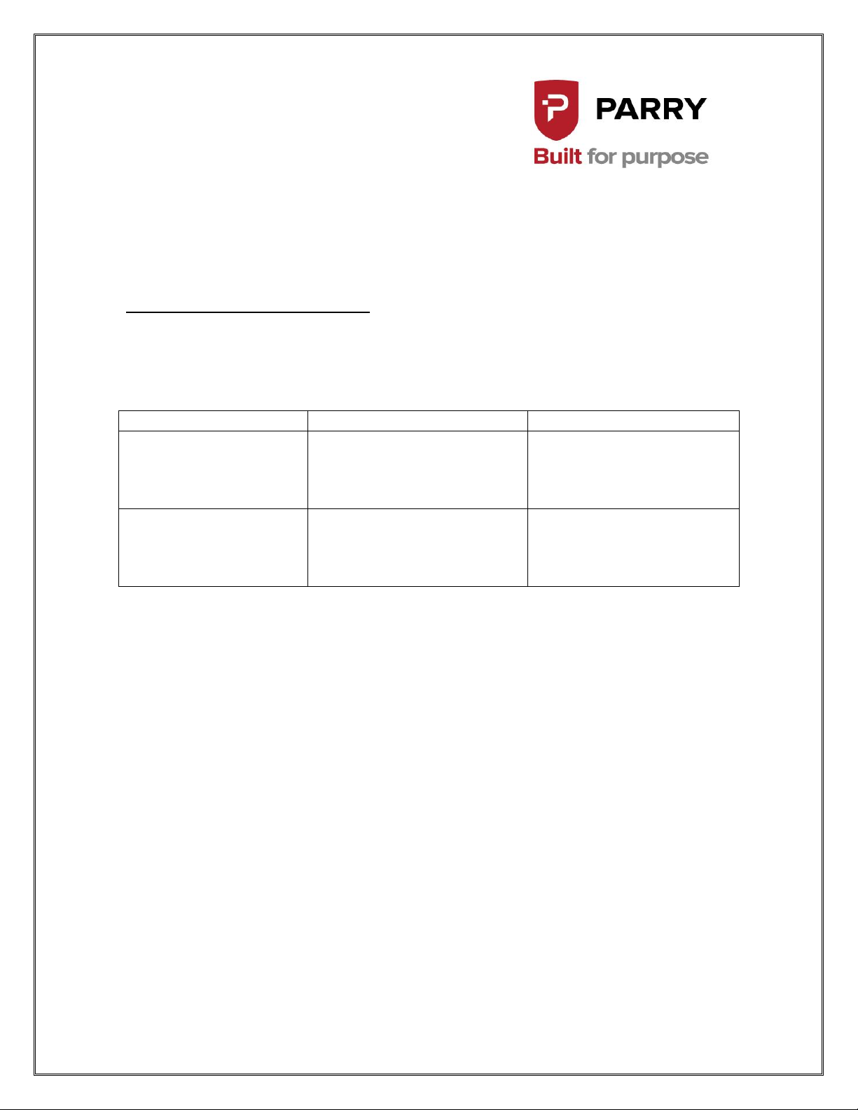
Model
Injector Code
Butane G30 @28mbar
11.2” W.G.
Propane G31 @ 37mbar
14.8” W.G.
INJECT119
Nat Gas G20 @ 20mbar 8”
W.G.
Nat Gas G25 @ 25mbar
10” W.G.
INJECT193
INSTRUCTION REF: IN173
ISSUE No. 2
DATE 17.12.09
Page 9 of 16
CONVERSION INSTRUCTIONS
This conversion must be carried out by a competent qualified person.
www.parry.co.uk
Page 10
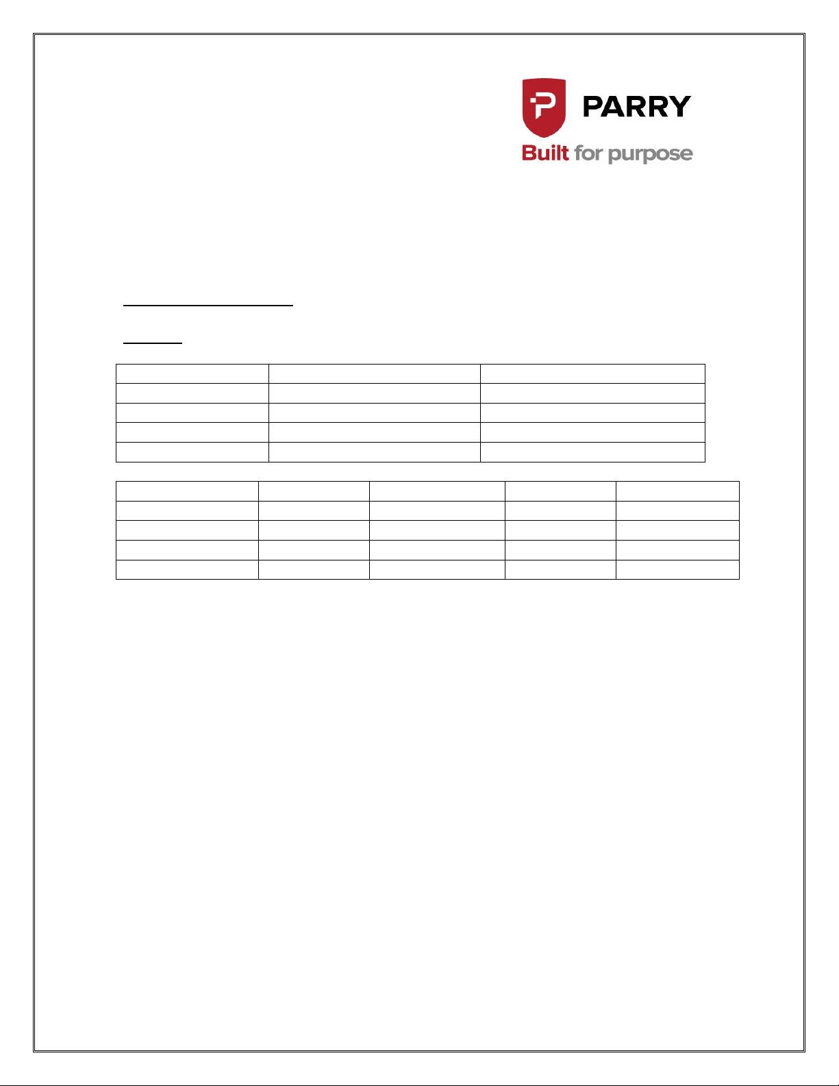
GAS
OPERATING PRESSURE
TOTAL HEAT INPUT
NATURAL G20
20mb/8” W.G.
10.86 KW = 37054Btu/h
BUTANE G30
29mb/11.2” W.G.
10.86 KW = 37054Btu/h
PROPANE G31
37mb/14.8” W.G.
10.86KW = 37054Btu/h
G25
25mb/10” W.G.
11.34KW = 30384Btu/h
GAS RATE
M³/HR
FT³/HR
LB/HR
KG/HR
NATURAL G20
1.0 M³/HR
35.9 FT³/HR
BUTANE G30
1.724 LB/HR
0.782 KG/HR
PROPANE G31
1.75 LB/HR
0.794 KG/HR
G25 @ 25mb
1.238 M³/HR
44.56 FT³/HR
INSTRUCTION REF: IN173
ISSUE No. 2
DATE 17.12.09
Page 10 of 16
TECHNICAL DETAILS
MODEL
INJECTORS
Natural G20 = INJECT193
Butane G30 = INJECT119
Propane G31 = INJECT119
G25 @ 25mb = INJECT193
www.parry.co.uk
Page 11
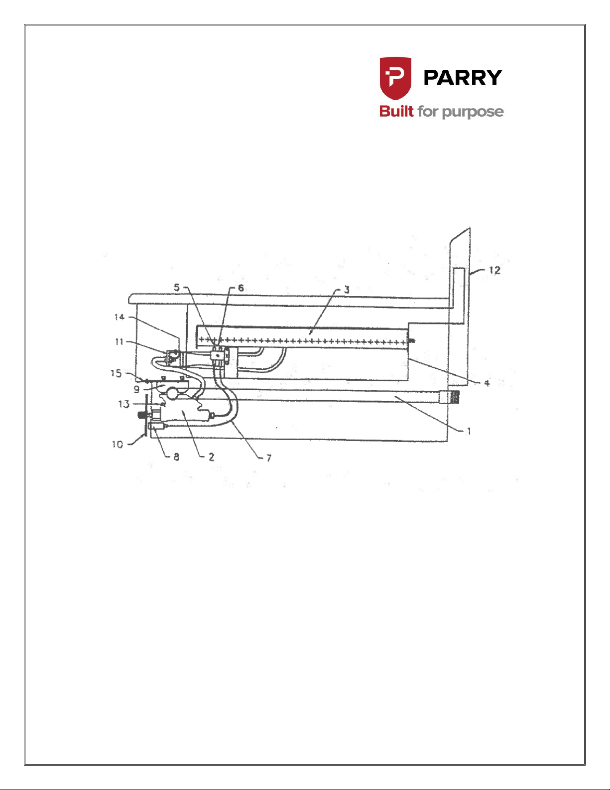
PART No.
DESCRIPTION
TUBES2HOB
1) FLOAT RAIL
GASTAP8MM
2) GAS COCK/FFD.8MM x 2
BURNER001
3) BURNER x 2
CHARBOX01
4) BURNER BOX
MBETC ASSY
5) THERMOCOUPLE x 2
MBETC ASSY
6) SPARK ELECTRODE x 2
CABLHT500
7) H.T. CABLE
PIEZOSP1
8) SPARK GENERATOR x 2
BRACKET01
9) SADDLE BRACKET
KNOBTYPEF
10) GAS COCK KNOB x 2
GRIDAERAT
11) AERATOR x 2
FLUECOVER
12) FLUECOVER
13) LOW RATE ADJUSTER
INJECT193
14) INJECTOR x 2
RAILPLATE
15) FLOAT RAIL MOUNTING PLATE
INSTRUCTION REF: IN173
ISSUE No. 2
DATE 17.12.09
Page 11 of 16
PARTS LIST
www.parry.co.uk
Page 12
INSTRUCTION REF: IN173
ISSUE No. 2
DATE 17.12.09
Page 12 of 16
www.parry.co.uk
Page 13
PART NO.
PART DESCRIPTION
BURNER001
Burner assembly
GASTAP 8/1
8 mm Tap Assembly Thermostat (2)
MBETCASSY
Thermocouple Electrode Assembly
KNOBPHEN
Knob
PIEZOISPI
Spark Generator
INJECT 193
Injector Natural
INJECT 119
Injector LPG
CABLHT500
Ignition HT Lead
LAVAROCKI
Bag of lava rock 2kg
CHARGERTOP
Top Grid
MESH TRAY
Mesh Lava Rock Tray
TUBES2HOB
Float rail
BRACKET01
Saddle bracket
PGC6 FLUE COVER
Flue cover
PGC6 FAT DRAWER
Fat drawer
INSTRUCTION REF: IN173
ISSUE No. 2
DATE 17.12.09
Page 13 of 16
SPARES LIST
www.parry.co.uk
Page 14
INSTRUCTION REF: IN173
ISSUE No. 2
DATE 17.12.09
Page 14 of 16
WARRANTY INFORMATION
WARRANTY POLICY
The manufacturers warranty is only valid in the UK mainland & Northern
Ireland, Western Isles, Inner Hebrides and Islands are parts only warranty.
All service calls will be carried out between the hours of 8.00am – 5.00pm
Monday to Friday only.
We accept no responsibility for delays in replacing or repairing the
equipment due to circumstances beyond our control.
Your warranty can be immediately invalid if the installation of the
equipment has not been installed in accordance with the manufactures
instruction. (See installation details). Also the miss-use, alteration or
unauthorised repairs of the equipment will invalidate the warranty.
During the warranty period it is at Parrys discretion to repair or replace the
equipment.
Warranty only applies if the equipment has been used in a professional
manor following the manufactures instructions and maintenance guide
lines.
The warranty covers defects in the material and components failure only
we are not liable for trading loss, loss of perishable items, water damage,
loss due to injury or fire damage.
WARRANTY REQUEST
Please ensure you have referred to the manufacturers’ instruction before
placing a warranty call. Or contact our warranty department on 01332
875665 for technical assistance. Please ensure you obtain the model
number before calling.
Please ensure you have read the section not covered under warranty to
avoid any unnecessary warranty charges.
If the problem with the machine can not be resolved please contact the
company that supplied you the machine.
(SERVICE CALLS CAN NOT BE PLACED DIRECT WITH PARRY)
www.parry.co.uk
Page 15

INSTRUCTION REF: IN173
ISSUE No. 2
DATE 17.12.09
Page 15 of 16
NOT COVERED UNDER WARRANTY
Fault due to poor maintenance.
Resetting of equipment or circuit breakers.
Abuse of the equipment
Foil should never be used on racks
Blockages eg, drains, condensers, pumps etc
Lime scale related issues
Installed incorrectly
Access arranged for service call and engineer refused access or customer
not there.
No faults with the machine.
Setting up of equipment eg, dishwasher detergents, levelling and setting
up of doors on a 6 burner cooker.
Excessive carbon build up on griddle plates.
Over use of lava rock on the chargrills recommended use by Parry 2kg
only.
Faulty electrics – eg, customers plug socket, plug, wiring, junction box
fault, wrong fuse.
Any damages caused by the customer.
Lamps, glass, door gaskets, Perspex, baskets, knobs all perishable items
are not covered.
www.parry.co.uk
Page 16
INSTRUCTION REF: IN173
ISSUE No. 2
DATE 17.12.09
Page 16 of 16
All of the above are not covered under our warranty policy. Any costs incurred
because of the above will be forwarded to the parties responsible for placing the
call.
Failure to pay any warranty charges will result in the customers warranty been
put on hold until the bill has been settled.
Any issues regarding the raised charges should be put in writing to our warranty
department for further investigation.
Parry Group Ltd
Town End Road
Draycott
Derby
England
DE72 3PT
www.parry.co.uk
 Loading...