

Page 1
Instruction Manual
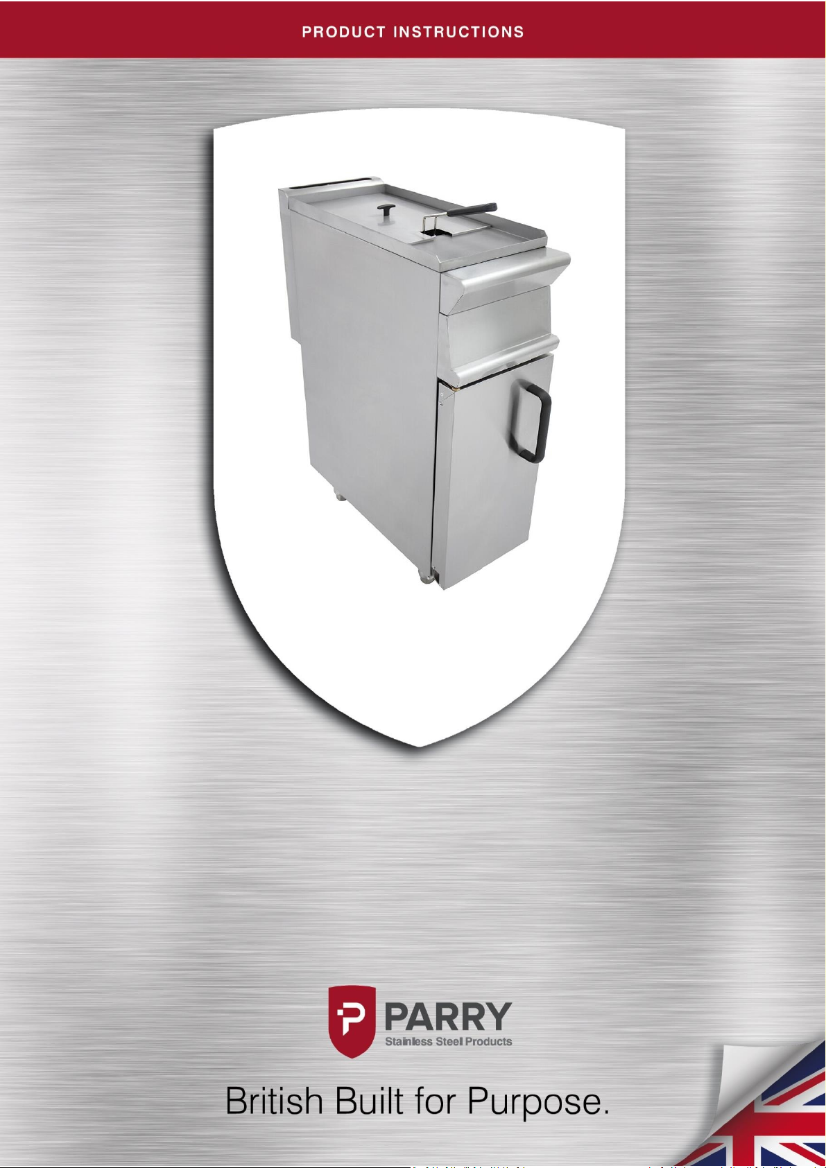
Single Pedastal Gas Fryer
GSF/GSFP
Page 2
Page 3

Contents
Parry-British Built for Purpose
IN273-4
1
Contents ...................................................................................................................................... 1
Product Overview ....................................................................................................................... 2
Safety Instructions ....................................................................................................................... 3
Installation Instructions ............................................................................................................... 4
Technical Data ............................................................................................................................. 5
Operating Instructions ............................................................................................................ 6-10
Cleaning Instructions ................................................................................................................. 10
Maintenance Instructions...................................................................................................... 11-12
Fault Finding ............................................................................................................................. 13
Service Information.................................................................................................................... 14
Exploded View ........................................................................................................................... 15
Parts List .............................................................................................................................. 16-17
Replacement Parts ..................................................................................................................... 18
Warranty Information ................................................................................................................ 19
Disposal & Recycling ................................................................................................................. 20
Parry Catering Equipment (Midlands) Ltd, Town End Road, Draycott, Derby, DE72 3PT.
Sales Tel: 01332 875544
Page 4
Parry-British Built for Purpose
IN273-4
2
Product Overview
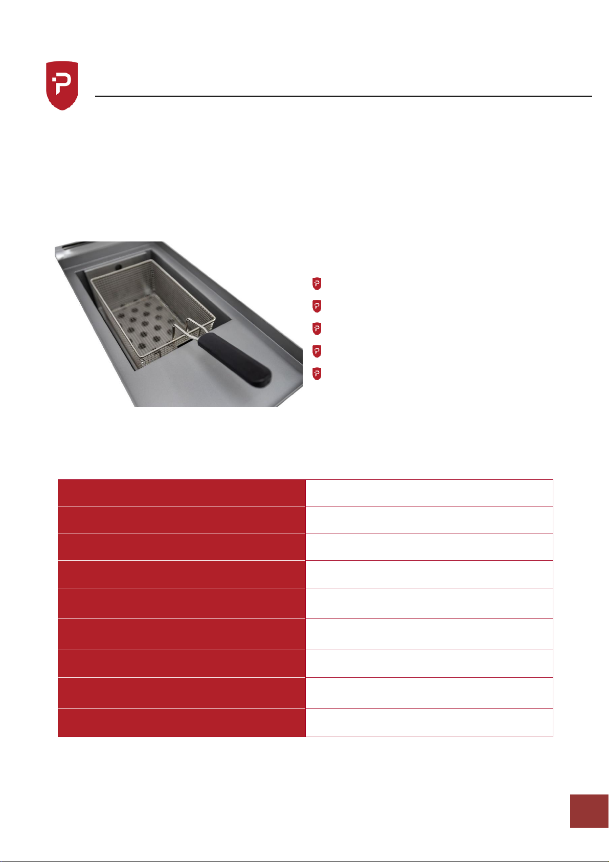
Powerful, robust and reliable, the Parry GSF natural gas pedestal fryer and GSFP LPG gas fryer
are essential for modern commercial catering establishments. The large 12 litre oil capacity and
the ability to fry up to 56kg of chips every hour make this fryer perfect for takeaways,
restaurants, schools and other businesses requiring both high quality and output. Made from
sturdy stainless steel and featuring simple thermostatic controls and drain valve, the fryer is
easy to use and clean.
It leads the industry in:
Design and aesthetic appeal
Performance
Power
Functionality
After sales support
Unpacked weight (kg)
56
Packed Wight (kg)
76
Dimensions (w x d x h) mm
300 x 790 x 970
Warranty
2 Year
KW – Natural
KW – Propane
9.5
10.5
BTU – Natural
BTU – Propane
40,842
42,275
Input Gas Connection
1/2” BSP Female
GAS INPUT PRESSURE – Natural
GAS INPUT PRESSURE – Propane
20 mbar
37mbar
Can be converted using conversion kit?
Yes
Page 5

Parry-British Built for Purpose
IN273-4
3
Safety Instructions
IMPORTANT
PLEASE READ INSTRUCTIONS FULLY BEFORE USE
IMPORTANT- YOUR ATTENTION IS DRAWN TO THE GAS SAFETY REGULATIONS. THIS APPLIANCE MUST
ONLY BE USED IN A WELL VENTILATED AREA. IT IS RECOMMENDED THAT A MINIMUM AREA OF 450mm²
PER 1 Kw (3400 Btu/HR) OF TOTAL INPUT MUST BE ALLOWED. PARTICULAR ATTENTION SHOULD BE
PAID TO THE SUPPLY OF CLEAN FRESH AIR AT LOW LEVEL TO THE APPLIANCE.
Attention is drawn to the requirement of the fryer to be fixed to the floor by means of fixing
holes in the flanged feet.
The data plate on the rear of the appliance must be checked to ensure the appliance is suitable
for the gas supply available. This appliance must be installed in accordance with the rules in
force.
Read the user instructions, read the installation instructions and ensure the correct ventilation
requirements are met. Attention should also be drawn to the need for regular servicing.
In normal use parts of the catering equipment may become hot, suitable precautions must be
taken to avoid accidental burns, therefore the appliance should be positioned to minimise the
risk of accidental touching. It is the responsibility of supervisors to warn users of this and
ensure the operators of this equipment are trained in safe operation of this appliance. It is
recommended the appliance be fitted below a ventilating hood, preferably of the extractor
type, incorporating a grease filter.
All commercial gas catering equipment is recommended to be mounted below an extraction
canopy. Please consult a ventilation engineer or refer to Guidelines DW172 to calculate the
ventilation requirements for cooking areas containing different pieces of gas catering
equipment.
Page 6

Parry-British Built for Purpose
IN273-4
4
Installation Instructions
POSITIONING
The appliance must not be installed on or against combustible surfaces – minimum clearances
must be:
Rear 150mm (6”)
Sides 150mm (6”) FROM ANY ADJACENT WALL
It is recommended that the appliance be sited below a ventilating hood preferably of the
extractor type incorporating a grease filter.
The minimum distance between the top of the appliance and any over shelf or ceiling
constructed of combustible material must be 1525mm (60”). All local fire regulations must be
observed before the appliance is commissioned the gas safety regulations require that all gas
connections on the gas line are tested for gas soundness between the gas meter and the
appliance. All packing and protective film must be removed from the panels etc. prior to
commissioning the appliance.
GAS CONNECTION
The gas connection is ½” B.S.P.T. on the left hand side rear of the fryer. The supply pipe must
not be less than ½”, an easily accessible isolation cock should be fitted in the pipework as close
as possible to the fryer. An approved flex may be used in conjunction with a straining cable.
Gas hoses used to connect the appliance to the gas supply must be of the correct specification
for the gas and pressure of the appliance. The gas hose must comply with the national
requirements in force, and be CE marked, of a metal braided construction suitable for
commercial catering equipment. The hoses should be periodically examined and replaced as
necessary
The tube or hose shall be fitted such that there are no sharp bends or torsional strain which
may cause damage or failure of the tube or hose, especially near the end fittings. Torsional
strain can be prevented by the use of internal unions, swivel joints, etc. The bend radius should
not exceed that stated by the Manufacturer. The hose should not touch the ground and should
be no longer than 1.5m long.
A manual valve should be positioned upstream of the tube or hose unless the connection fitting
incorporates a self-sealing quick release coupling.
Where a quick release coupling is used for horizontal travel such as in commercial catering
appliances it is advisable that the coupling is facing downwards to prevent the ingress of debris
and ensure the hose is formed in to a smooth curve.
All units should have a restraining cable fitted preventing the unit from being pulled away from
the wall and causing the gas hose to become disconnected accident
Page 7
Parry-British Built for Purpose
IN273-4
5
Technical Data
Technical Data
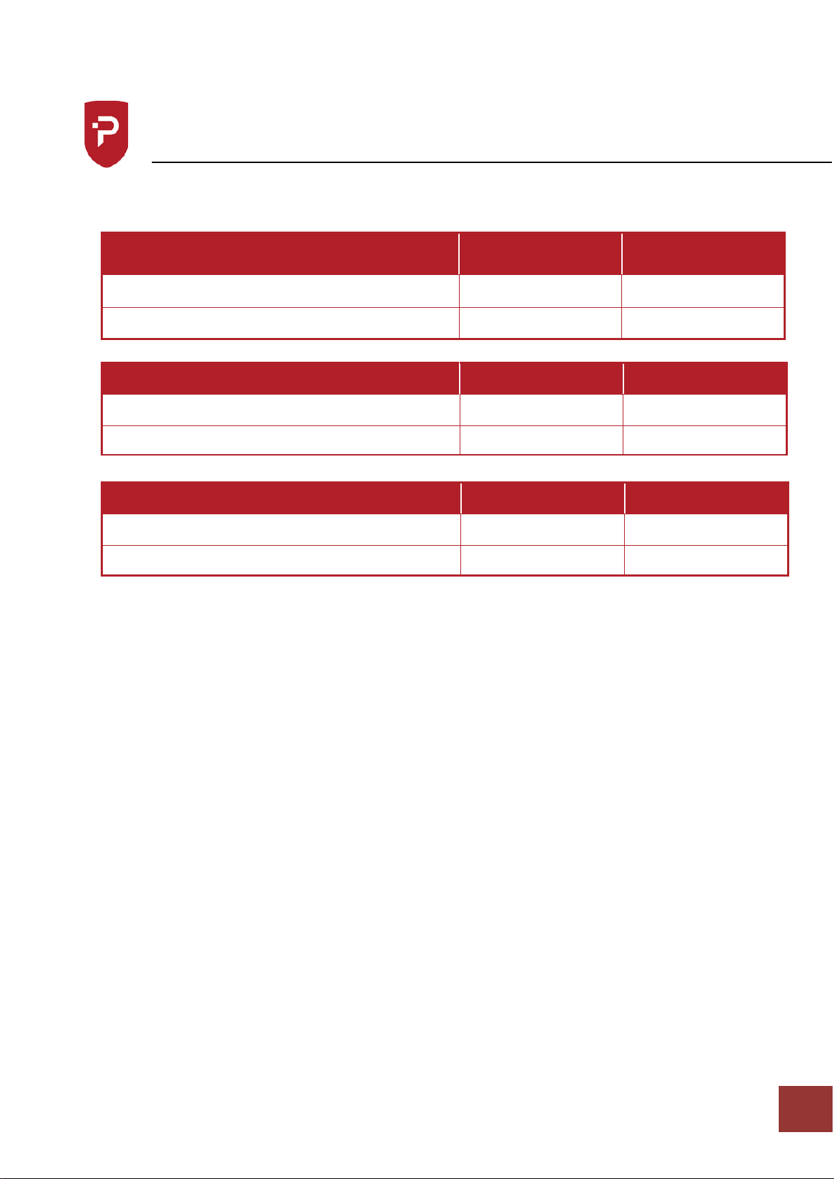
TEST DATA GSF FRYER
GAS
TOTAL HEAT INPUT
(NETT)
TOTAL GAS RATE
NATURAL GAS G20 @ 20mbar
9.53 kw
1.008 M3/hr
PROPANE GAS G31 @ 37mbar
10.49 kw
0.429 M3/hr
GAS
INJECTOR
PILOT INJECTORS
NATURAL GAS G20 @ 20mbar
INJECT0230
PINJ76378
PROPANE GAS G31 @ 37mbar
INJECT0160
PINJ76371
GAS
PILOT RATE
FULL RATE
NATURAL GAS G20 @ 20mbar
0.055 M³/HR
1.008 M³/HR
PROPANE GAS G31 @ 37mbar
0.015 M³/HR
0.429 M³/HR
Page 8
Parry-British Built for Purpose
IN273-4
6
Operating Instructions
The attention of the user is drawn to the current Gas Safety (Instructions and Use)
Regulations in force. This appliance must be used in accordance with these, also the need
for regular servicing which must be carried out by a competent and qualified person.
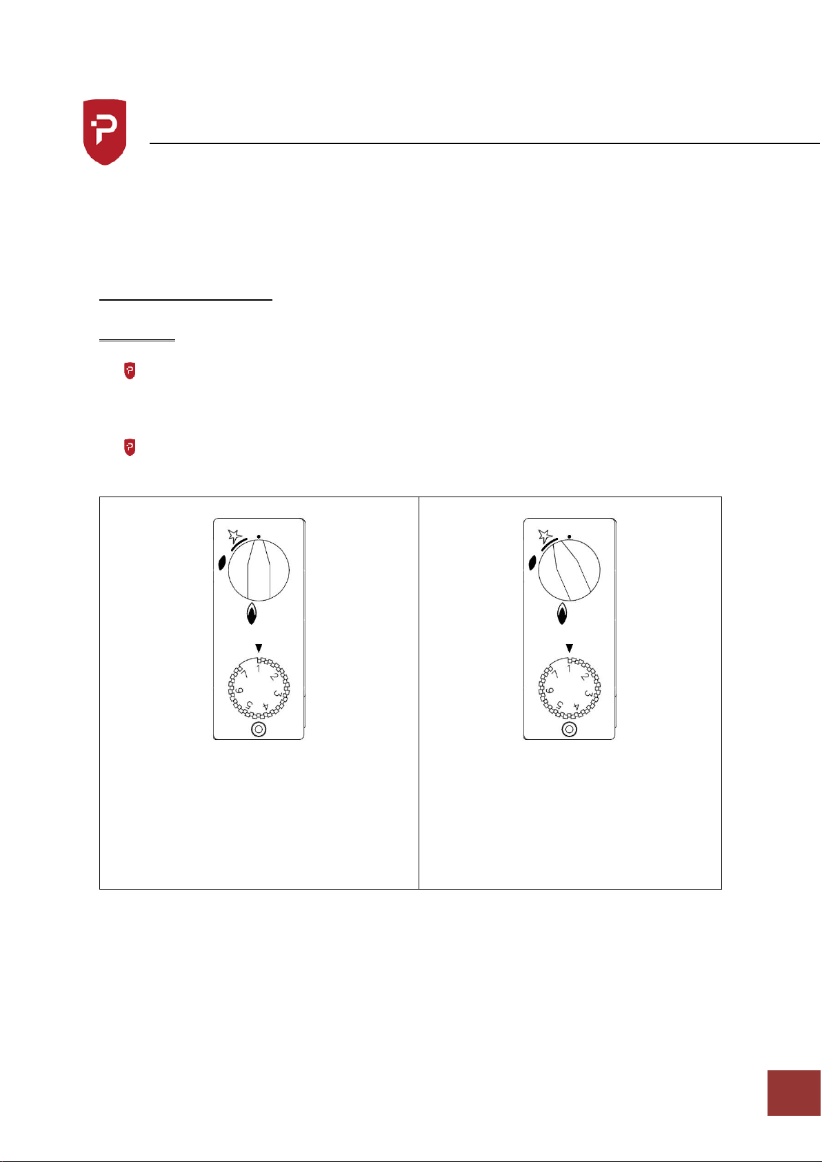
LIGHTING INSTRUCTIONS
WARNING: DO NOT LIGHT BURNERS WHEN THE PAN IS EMPTY
Open the compartment door, ensure the drain valves are closed and check the level of
cooking oil (between maximum and minimum markings). The oil required to fill the pan to
the correct level is 12 litres per pan.
Turn on the gas supply.
1) Turn the thermostat to position 1.
2) Turn top control knob anticlockwise
until stops, Press control knob in and
turn anticlockwise to Ignite pilot. If
pilot fails to ignite, repeat the
procedure until pilot is lit. Hold knob
in for 20-30 seconds to ensure pilot
flame is fully established.
Page 9
Parry-British Built for Purpose
IN273-4
7
Operating Instructions
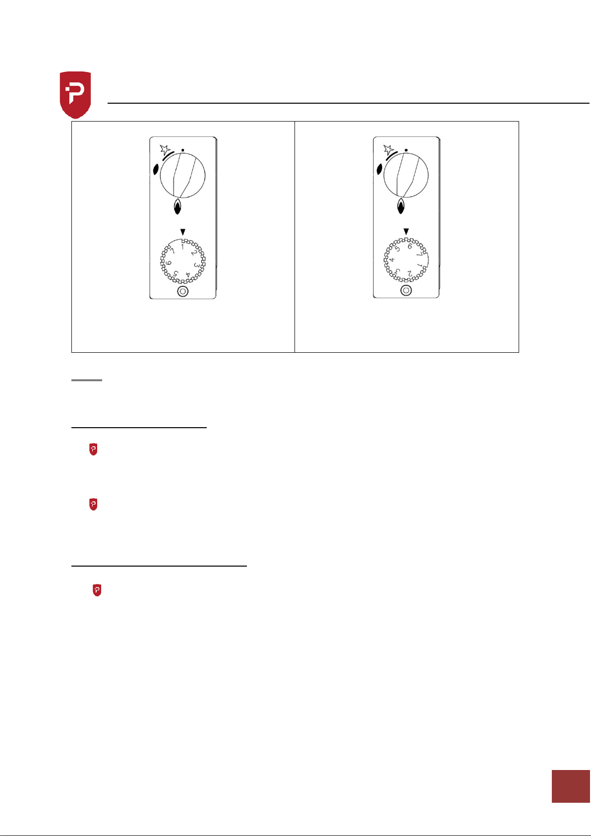
1) Release the knob and turn fully anti-
clockwise to main burner position.
2) Turn the thermostat dial to the
appropriate setting
(Please note if using solidified oil or fat
follow the steps below)
NOTE: LIDS SHOULD NOT BE USED WHILST FRYING
SHUT DOWN OF THE FRYER
When appliance is not required for cooking, turn control knob clockwise to the pilot setting
this will leave the fryer ready for the next time. Turn back to main burner setting once
required and adjust thermostat to the required setting.
To turn the unit off completely, turn the control knob clockwise to the off position and turn
off gas supply.
USE OF SOLIDIFIED OIL OR FAT
In an empty pan
IMPORTANT: If solidified oil or fat is to be used, remove the grid from the bottom of the pan,
break the solidified oil or fat into small pieces and fill the V shaped bottom of the pan.
Light the appliance and turn the thermostat knob to 130˚C (Setting 2). Continue to add pieces
of fat into the pan until the V shaped bottom is filled with the molten fat. If the fat appears
to be overheating, turn the thermostat OFF, continue to add fat and turn the thermostat ON
when the fat has cooled.
Refit the grid and put the remaining oil or fat into the pan until the level is up to the
mark. Allow to heat up slowly until all the fat has melted, then turn the thermostat knob to
the required cooking temperature.
Page 10

Parry-British Built for Purpose
IN273-4
8
Operating Instructions
Already solidified in the pan
Light the appliance and turn the thermostat ON for approximately 5-10 seconds, and then
turn OFF again. Leave it for 30 seconds before repeating the 5-10 seconds cycle.
Continue to repeat until the fat has melted so that any remaining un-melted pieces are free
floating, then turn the thermostat to the required temperature.
COOKING INSTRUCTIONS
With the thermostat knob turned to the required cooking temperature, allow the oil or fat
to heat up for about 20 minutes before starting to cook. After each load is removed from
the fryer always allow 2½ minutes for the temperature of the oil to recover before the next
load is put into the oil.
THE FRYING MEDIUM
Ensure oil is always maintained at the level indicated. Good quality vegetable oil is
recommended. The life expectancy of oils will be lengthened if they are filtered regularly –
food particles not removed turn rancid and reduce oil quality. The life of the oil will also be
extended if the temperature is turned down when the fryer is not is use.
“Please note also, using old oil will reduce the flash point and therefore present a greater
fire hazard and be more prone to surge boiling. Attention should also be drawn to the effect
of over-wet food and too large a charge on surge boiling”.
Chip Frying
The recommended load for each batch is 1.4 kg (3 lbs) for each basket. This will fill the
basket about 2/3rd full and it is important that this load should not be exceeded.
Fish Frying
Cook fish by free floating them. Four or five 100g pieces may be cooked at one time. Slide
the fish into the pan slowly to avoid splashing of the oil or fat and prevent the fish sinking
and sticking to the base of the pan.
Page 11
Parry-British Built for Purpose
IN273-4
9
Operating Instructions
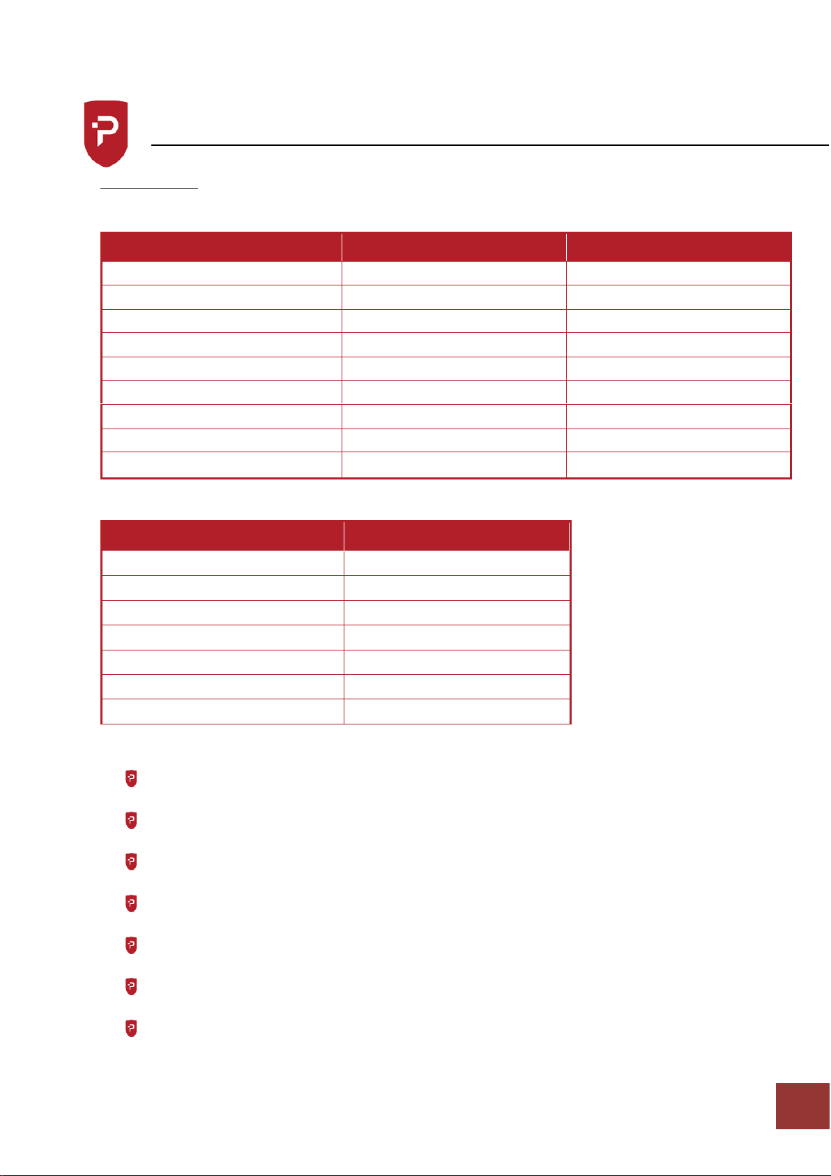
Cooking Chart – the following chart is for guidance only.
Maximum basket load not to exceed 3 lbs
Food
Time
Temperature
Chicken pieces
5-8 mins
175°C
Chipped potatoes (Blanched)
3 mins
165°C
Chipped potatoes (Browning)
1-2 mins
190°C
Chipped Potatoes (Raw)
4-5 mins
190°C
Doughnuts
3-4 mins
170°C
Fish fillets
5-7 mins
175°C
Fritters
3-4 mins
175°C
Potato Chips
2 mins
190°C
Scampi
3-4 mins
175°C
Temperature Settings
STAT No.
Temperature
1
120°C
2
135°C
3
145°C
4
160°C
5
175°C
6
185°C
7
195°C
ALL THE ABOVE ARE +/- 5°C
To Obtain Best Results
Keep the pan clean
Use good quality oil or fat which has high breakdown temperature
Use only clean oil or fat and strain daily.
Maintain the oil or fat at the correct level
Do not start to fry until the oil has reached the correct temperature
Do not exceed the temperature of the oil or fat as recommended by the supplier.
Do not overload the fryer.
Page 12
Parry-British Built for Purpose
IN273-4
10
Operating Instructions
Remove the crumbs or pieces floating on the surface of the oil.
When using frozen foods follow the food manufacturers cooking instructions
carefully
To conserve energy, turn the thermostat knob to the OFF position during breaks in
frying.
Cleaning Instructions
DRAINAGE
Always allow the oil to cool to a maximum 55˚C before draining.
Remove the blanking nut from drain tap, fit discharge pipe into tap, drain oil into
suitable receptacle, taking care not to overfill so that it is not difficult to handle.
Excess oil in the base of the tank can be removed with kitchen paper.
For best results oil should be drained and filtered every day the fryer had been used.
This will prolong the life of the oil.
CLEANING INSTRUCTIONS
The appliance should be cleaned with hot water and a mild detergent,
DO NOT USE ABRASIVES.
Isolate the appliance from the gas supply.
Allow oil to cool to maximum 55˚C.
Drain as per instructions for draining.
Wash tank and top surface of the fryer body.
Clean the drain tube assembly, using a tube or flue brush suitable for 15mm tube, with
the drain tap in the open position. Clean by inserting brush into inlet and outlet of drain
tube.
Wash all parts thoroughly with hot soapy water, do not use abrasive materials.
Ensure all parts are thoroughly rinsed and dried. To ensure there is no water left in the
drain tube, flush with a small amount of clean cooking oil.
Re-assembly in reverse order.
Stainless steel cleaners maybe used and cleaning instructions on the product must be
adhered to.
Never clean the unit with water jets.
Page 13
Parry-British Built for Purpose
IN273-4
11
Maintenance Instructions
Ensure the appliance is isolated from the power supply before installing, cleaning or
maintaining the appliance.
Maintenance and service must only be undertaken by a qualified electrician.
Parry Catering provides a complete after-sales service by offering the sales of spare parts
directly to customers. Buying spares straight from the manufacturer allows customer to
experience exceptional value and speedy delivery on all spare parts.
For more information on buying spares visit:
www.parry.co.uk/parry-commercial-catering-spares
The use of old oil or food with a high moisture content can reduce the flash
temperature and can cause overheating of the oil.
Fryers should never be left unattended
Oil should not be added or drained from the unit while the unit is hot. The appliance
should be turned off and left to cool to a maximum of 55˚C before adding or removing
oil.
Flammable solvents and cleaning aids should not be used on this appliance
The tank has a marking on it to indicate how much oil must be put into the tank. It is
important not to over fill or under fill the tank.
Page 14

Parry-British Built for Purpose
IN273-4
12
Maintenance Instructions
ROUTINE MAINTENANCE
To be carried out by an engineer
Ensure fryer is filled with oil.
Fit pressure gauge to multifunction valve and go through lighting procedure, check
flame failure device opens in no more than 30 seconds.
Turn thermostat to 150°C and check that the pressure at the test point is:
o NATURAL GAS 20mb ( 8” W.G.)
o PROPANE GAS 37mb (14” W.G.)
o Adjust governor if necessary.
Only leave burner on for a minimum amount of time to ensure fryer does not get too
hot.
Turn the thermostat to off and ensure the burner has extinguished completely within
3-4 seconds.
Turn the thermostat on again to 150°C and ensure the burner cross lights smoothly
from the pilot.
Check burner flames are uniform and there is no spillage of the flames away from the
heat exchanger.
Turn the thermostat off and blow out the pilot. Check that the flame failure valve
closes within 60 seconds. This can be done by feel or sound.
Turn off the gas, remove pilot and withdraw burner assembly, clean the burner parts
and ensure the injectors are clear.
Reassemble the pilot and main burners.
Go through the lighting up procedure, turn the thermostat to 150°C and allow to heat
up. Check the thermostat cuts out the gas, turn the thermostat to 190°C, allow to heat
up and note the oil temperature is 190°C+5°C.
Page 15
Parry-British Built for Purpose
IN273-4
13
Fault Finding
Fault
Check
Solution
Piezo Ignitor not sparking
Short in the High Tension Lead
Replace Lead
Fractured Electrode Insulator
Replace Electrode
No spark being generated at all.
Replace Piezo
Pilot burner will not light or stay
lit
Thermocouple / interrupter
connections not secure
Tighten Connection
TEST: Is there gas at the point
when holding the control knob in
the pilot position:
Yes
Check over temperature stat for
open circuit and then check
thermocouple voltage (min.
15mv)
Yes, Very Little
Check supply, then check pilot jet
for blockages and clean if
necessary.
No
Check Supply.
If all the above are OK control valve is faulty
Over temperature stat operates
Check if the temperature is over
220°C
If not, replace Control Stat
TEST: Check if the control stat
operates on temp. rise when set
point is low / 100°C
If yes, check calibration of the
control stat. (See Installation
instructions for details)
Manually reset over temperature
stat
If not working
Replace Control stat then
manually reset over temperature
stat.
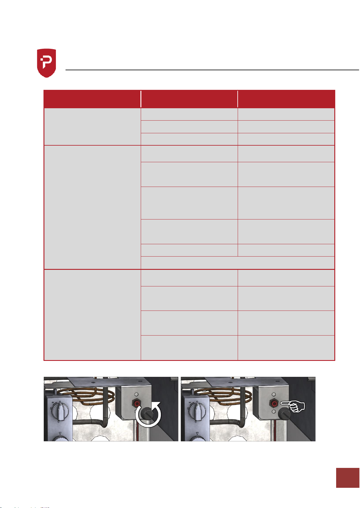
Resetting the over temperature thermostat
Unscrew the dust cap and press the centre of the button using a pen until you hear it
click.
Page 16

Parry-British Built for Purpose
IN273-4
14
Service Information
This appliance should be routinely serviced to prolong its lifetime. Parry recommends that
the appliance is serviced every 12 months by a Parry authorised engineer. Failure to service
your product within the initial 12 month warranty period will cause the 24 month warranty
to become void.
If the supply cord becomes damaged, it must be replaced by the manufacturer, it’s service
agent, or a similarly qualified person.
Enhanced 2 Years Warranty
Parry Catering (Midlands) Ltd offer an enhanced warranty of two
years (including parts and labour) on all of the Parry manufactured
products. To take advantage of this you should register you warranty
by logging onto the company website and filling out our simple form.
www.parry.co.uk/the-parry-warranty
If you have any issues with your product and wish to request a
warranty call you can contact our friendly team who will organize a
Parry approved service engineer to attend and fix your problem.
All warranty requests can be sent to [email protected]
alternatively call our warranty department for technical
assistance on 01332 875544
Page 17
Parry-British Built for Purpose
IN273-4
15
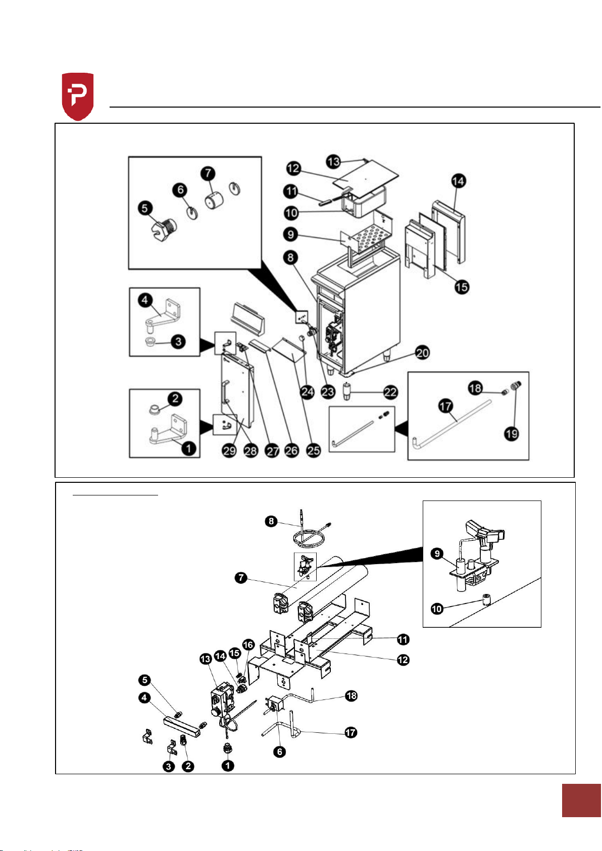
Exploded View
Main Assembly
Burner Assembly
Page 18

Parry-British Built for Purpose
IN273-4
16
Parts List
Main Assembly
Part Number
Description
Code
1
Bottom LH Hinge
ULT6BOHINGEBL
2
Hinge Pin Bush
ULTHINGEBUSH
3
Hinge Pin Bush
ULTHINGEBUSH
4
Top LH Hinge
ULT6BOHINGETL
5
Gland Nipple
NIPP67061
6
Gland Disc
DISC67061
7
Graphite Seal
SEAL07000
8
*Body
*NO CODE
9
*Batter Plate
*NO CODE
10
Fryer Basket
BASKETGFR
11
Plastic Handle
HANDLBASK
12
*Lid
*NO CODE
13
Tee Knob
TEEKNOB
14
*Flue Cover
*NO CODE
15
*Inner Flue
*NO CODE
16
12mm Equal Tee
N/A
17
12mm Inlet Pipe
NEWFRYERPIPE
From April 2021 Replaced with
GSFGASRAIL
18
15mm - 12mm Reducing Set
REDS1512F
From April 2021 Replaced with
GSFGASRAIL
19
15mm x 1/2" BSP Connector
CONNECT15
From April 2021 Replaced with
GSFGASRAIL
17,18.19
Complete GSF Rail
GSFGASRAIL
20
Leg Plate
LEGPLATE
21
N/A
N/A
22
Hex Leg
LEG50-100HEX
23
Drain Valve
ULTVALVE1
24
Drain Valve Cap
ULTFRYBLANK
25
*Drip Guard
*NO CODE
26
Roller Catch Bracket
LCPP4BODOORKEEP
27
Roller Catch Assembly
*NO CODE
28
Door Handle
GB6HANDLE
29
*LH Door Assembly
*NO CODE
*Metalwork Components
Page 19

Parry-British Built for Purpose
IN273-4
17
Parts List
Burner Assembly
Part Number
Description
Code
1
15mm x 3/8 BSPT
GDF15ADAPT
1a
15mm – 12mm Reducing Set
REDS1512F
2
8mm x ¼ Tapper Compression
Coupling
COUPLE8MM
3
Manifold Strap (Part of MANIFOLD1)
4
Injector Manifold
MANIFOLD1
5
Burner Injector
NAT Gas = INJECT0230
LPG Gas = INJECT0160
6
Over Temperature Thermostat
TMST07000
Replaced with TMSTRDC700
7
Burner
BURNR7000
8
Universal Thermocouple
THCP900MM
9
Pilot Assembly cw Electrode & Pilot
Injector
Setup for LPG gas
PILOT7000ADJ-LPG
Setup for NAT gas
PILOT7000ADJ-NAT
10
Pilot Injector
(If required without pilot assembly)
NAT Gas = PINJ76378
LPG Gas = PINJ76371
11
*Pilot Bracket
*NO CODE
12
*Burner Carriage
*NO CODE
13
GV30 Gas Valve
VALVEGDSF
14
8mm x 3/8 BSPT
GDFSADAPT
15
6mm Pilot Shear Nut
VALVECDFFITT
16
Interrupter
VALVETHCINT
16a
Interrupter Lead
GDSFINTLEAD
17
6mm Pilot Pipe
GFPILOTPIPE
18
8mm Burner Pipe
GFBURNERPIPE
GV30 Gas Valve Blanking Plug
VALVEGDFPLUG
*Metalwork Components
Page 20

Parry-British Built for Purpose
IN273-4
18
Replacement Parts
Please not parts should only be replaced by a qualified engineer
PILOT JET AND ELECTRODE
Undo pilot feed from gas valve, undo thermocouple from valve, remove screw from pilot
bracket, pilot assembly, c/w thermocouple and ignitor can now be removed.
THERMOCOUPLE
Undo thermocouple from gas valve; release probe end from the bracket on the pilot
assembly. Fit new in reverse order.
CONTROL THERMOSTAT
Drain fryer
Remove screws from mounting bracket
Remove the thermostat gland nut
Release thermostat phial from clip inside tank
Pull stat through tank, there will be some resistance felt due to the packing gland
being compacted.
Re-assemble in reverse order
Calibration of the thermostat where necessary is made by the screw in the centre of
the thermostat spindle. Clockwise to decrease temperature. Anti-clockwise to
increase.
CONTROL VALVE
Disconnect the gas supply pipe work and pipe to burners.
See previous notes for removal of pilot/thermocouple assembly, also thermostat
assembly.
Remove screws securing valve to bracket.
Remove fittings from valve to fit into replacement valves, as these are not supplied
with new valve.
Refit in reverse order.
SAFETY THERMOSTAT
Drain fryer
Remove spade connections on thermostat
Remove the two screws securing thermostat to bracket
Undo the gland nut on the tank and withdraw thermostat phial from bracket,
through the wall of the tank.
Fit new thermostat in reverse order.
Page 21

Parry-British Built for Purpose
IN273-4
19
Warranty Information
Not covered under warranty
Fault due to incorrect installation, poor maintenance
or equipment abuse.
Resetting of equipment or circuit breakers.
Faulty electrics – e.g. customer’s plug socket, plug,
wiring, junction box fault, wrong fuse.
Products must be serviced within the first 12
months to be eligible for the 2 year warranty
Product not covered by warranty if combustible
materials have been used, e.g. plastic trays.
Foil used on racks, blockages and lime scale issues.
Failure to grant access for pre-arranged service
call.
Equipment that has been set up or used incorrectly
e.g. dishwasher detergents, levelling and setting up
of doors on a six burner cooker.
Excessive carbon build-up on griddle plates or
overuse of lava rock on chargrills. (Recommended
use by Parry no more than 2kg.)
All of the above points are not covered by
warranty and any costs incurred, because of the
above, will be forwarded to the parties responsible
for placing the call.
The manufacturer’s warranty is only valid in the UK
mainland. Northern Ireland, Western Isles, Inner
Hebrides and Islands are parts only warranty. Please
be aware that the warranty starts from the date of
purchase from Parry and not the sale or installation
date of the equipment.
To be eligible for a 2 year warranty, products must be
serviced at least once within the first 12 months of
purchase.
All service calls will be carried out between 8am
and 5pm, Monday to Friday.
Your warranty is invalid if your equipment has not
been installed in accordance with the
manufacturer’s instructions. The misuse, alteration
or unauthorised repairs of the equipment will also
invalidate the warranty.
During the warranty period it is at Parry’s
discretion whether to repair or replace the
equipment.
The warranty only applies if the equipment has
been used in a professional manner following the
manufacturer’s instructions and maintenance
guidelines.
The warranty covers defects in the material and
component failure only. We are not liable for trading
loss, loss of perishable items, water damage or loss
due to injury or fire damage.
Please ensure you have referred to the
manufacturer’s instruction before placing a warranty
call.
Contact our warranty department on 01332 875544
for technical assistance.
Please have your model number ready before calling.
All warranty requests must be submitted to
Failure to pay any warranty charges will result in your
warranty being put on hold until the bill has been
settled. Any issues regarding the raised charges should
be put in writing to our warranty department for
further investigation.
Register your product by visiting our website
www.parry.co.uk
Page 22

Parry-British Built for Purpose
IN273-4
20
Disposal & Recycling
The packaging should be disposed of in accordance with the regulations in force.
 Loading...