

Page 1
Instruction Manual
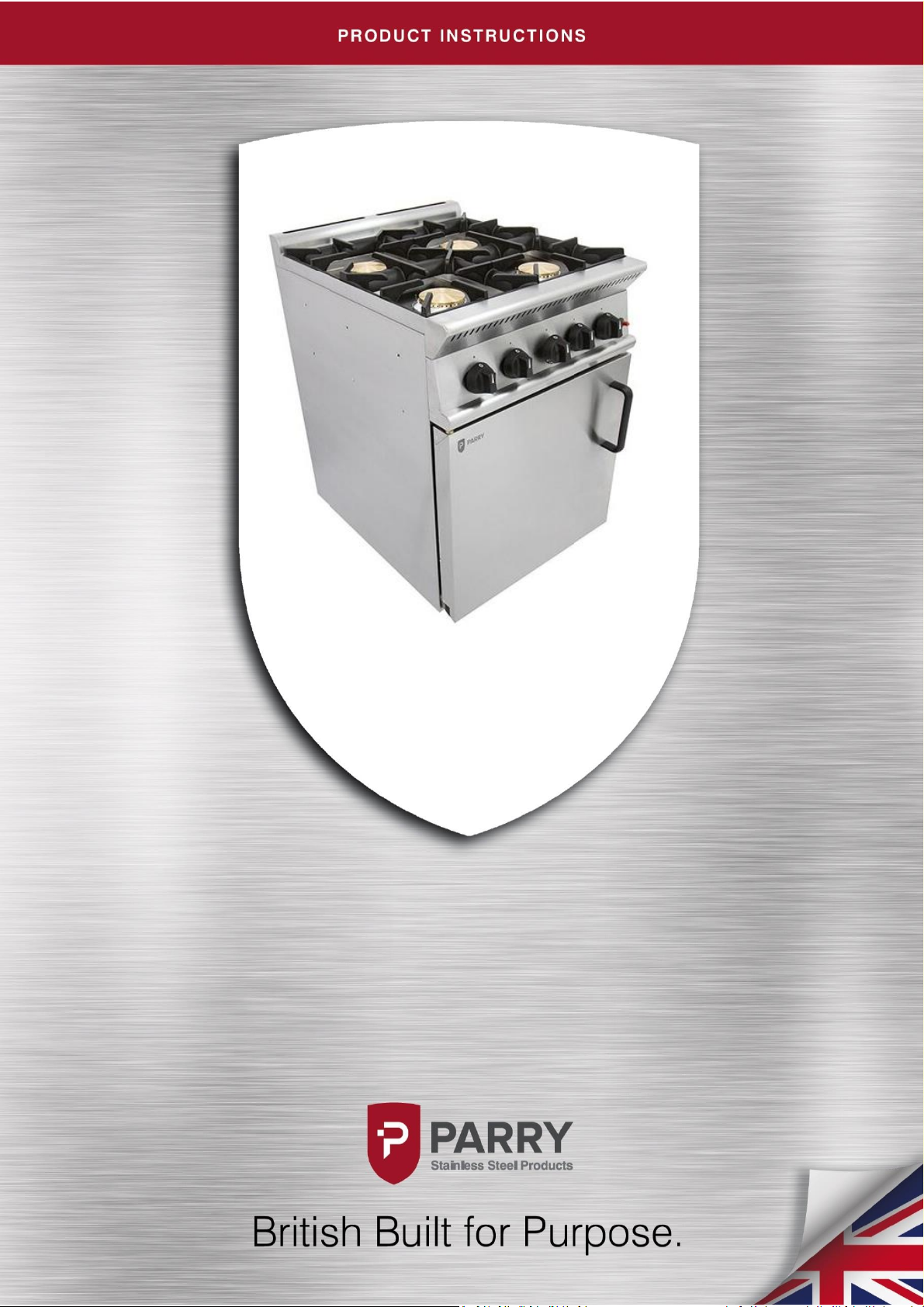
Gas 4 Burner Cooker
GB4/GB4P
Page 2
Page 3

Contents
Parry-British Built for Purpose
IN272-3
1
Contents ...................................................................................................................................... 1
Product Overview ....................................................................................................................... 2
Safety Instructions ....................................................................................................................... 3
Installation Instructions ............................................................................................................ 4-6
Operating Instructions .............................................................................................................. 6-7
Cleaning Instructions ................................................................................................................... 8
Maintenance Instructions............................................................................................................. 9
Fault Finding ............................................................................................................................. 10
Replacement Parts ..................................................................................................................... 11
Natural Gas Conversion Instructions .......................................................................................... 12
LPG Gas Conversion Instructions ................................................................................................ 13
Conversion Procedure ........................................................................................................... 14-16
Technical Information ............................................................................................................... 17
Exploded View ........................................................................................................................... 18
Service Information ................................................................................................................... 19
Parts List .............................................................................................................................. 20-22
Warranty Information ................................................................................................................ 22
Disposal & Recycling ................................................................................................................. 23
Parry Catering Equipment (Midlands) Ltd, Town End Road, Draycott, Derby, DE72 3PT.
Sales Tel: 01332 875544
Page 4
Parry-British Built for Purpose
IN272-3
2
Product Overview
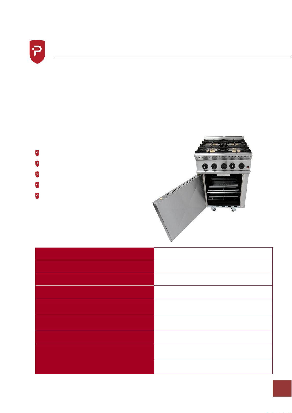
Reliable, powerful and robust, the Parry GB4 commercial oven is an ideal solution for
modern catering establishments. The sturdy, compact design includes four powerful hob
burners with robust, heavy duty pan supports, while the oven itself has one burner and easy
push-button piezo ignition. Robust and responsive dial controls and easy-to-clean vitreous
enamel lining add to the oven’s overall functionality. Constructed with strong stainless steel
and with durable castors, the oven is an essential addition to commercial catering
establishments requiring reliability and performance
It leads the industry in:
Design and aesthetic appeal
Performance
Power
Functionality
After sales support
Unpacked weight (kg)
100
Packed weight (kg)
120
Dimensions (w x d x h) mm
600 x 790 x 970
Warranty
2 Years
KW – Natural
KW – Propane
29.032
25.544
BTU – Natural
BTU – Propane
99,050
83,560
Input Gas Connection
Male ¾” BSP
GAS INPUT PRESSURE – Natural
GAS INPUT PRESSURE – Propane
20mb / 8” W.G
37mb / 14.8” W.G.
Can be converted using conversion kit?
Yes
Page 5

Parry-British Built for Purpose
IN272-3
3
Safety Instructions
IMPORTANT
PLEASE READ INSTRUCTIONS FULLY BEFORE USE
THIS APPLIANCE IS ONLY FOR PROFESSIONAL USE AND MUST ONLY BE USED BY QUALIFIED
PEOPLE.
Attention should be drawn to the fact that parts of this unit by necessity, will get VERY HOT,
and will cause burns if touched accidentally. Therefore, it is the responsibility of the
supervisor or equivalent to provide SUITABLE PROTECTIVE CLOTHING for the user.
THIS APPLIANCE MUST BE FITTED AND TESTED BY A REGISTERED FITTER BEFORE USE.
The unit should be installed in compliance with the INSTALLATION INSTRUCTIONS and the
NATIONAL REGULATIONS in force at the time. Particular attention should be paid to the Gas
Safety (Installation and Use) Regulations and the Health and Safety at Work Act.
All commercial gas catering equipment is recommended to be mounted below an extraction
canopy. Please consult a ventilation engineer or refer to Guidelines DW172 to calculate the
ventilation requirements for cooking areas containing different pieces of gas catering
equipment.
Each appliance requires a flow of fresh air for combustion. Under no circumstances should
air vents on the appliances, or air vents installed by the fitter in the room of the appliance to
supply combustion air, be altered or omitted in any way.
To prevent shocks, all appliances whether gas or electric, must be earthed.
ANY GAS CONVERSIONS NEEDED TO BE MADE TO THE PRODUCT MUST BE CARRIED OUT
BY A GAS SAFE REGISTERED ENGINEER
To avoid scratching the highly polished exterior surface of this equipment whilst in transit,
the protective film on the exterior surfaces has NOT been removed.
It is IMPORTANT that this protective film is peeled off before the equipment is used.
Page 6

Parry-British Built for Purpose
IN272-3
4
Installation Instructions
ALL APPLIANCES MUST BE FITTED AND OR CONVERTED BY A REGISTERED INSTALLER, IN
ACCORDANCE WITH CURRENT REGULATIONS.
Before installation check data plate on rear of unit to ensure appliance is suitable for gas
supply available.
During installation provision must be provided for combustion air to the appliance through
base and rear of appliance. This should not be blocked at any time. This appliance should be
installed with adequate ventilation to prevent the occurrence of unacceptable
concentrations of substances harmful to health in the room in which it is installed.
POSITIONING
The appliance must not be installed on or against combustible surfaces – minimum
clearances must be: Rear 150mm (6”)
Sides 150mm (6”)
Hotplate to combustible material 1525mm (60”)
All local fire regulations should be observed. It is recommended that the appliance be sited
below a ventilating hood preferably of the extractor type incorporating a grease filter.
The cooker is manufactured with four castors two of which are braked. Caution should be
taken when manipulating or moving the unit. The appliance should be attached to a wall with
a chain to restrict the movement of the unit once connected to the gas supply. When the unit
is installed in position the brakes should be on.
Ensure the appliance is level, by placing a spirit level on the shelf in the oven, not on the pan
supports. All four castors are adjustable. To alter the height of the unit, loosen the locking
grub screw with an M3 allen key.
Next turn the large nut on the wheel assembly to either raise or lower the unit. When you are
happy with the height, tighten the locking grub screw with the M3 allen key.
Locking Grub
Screw
Large Nut
Page 7
Parry-British Built for Purpose
IN272-3
5
Installation Instructions
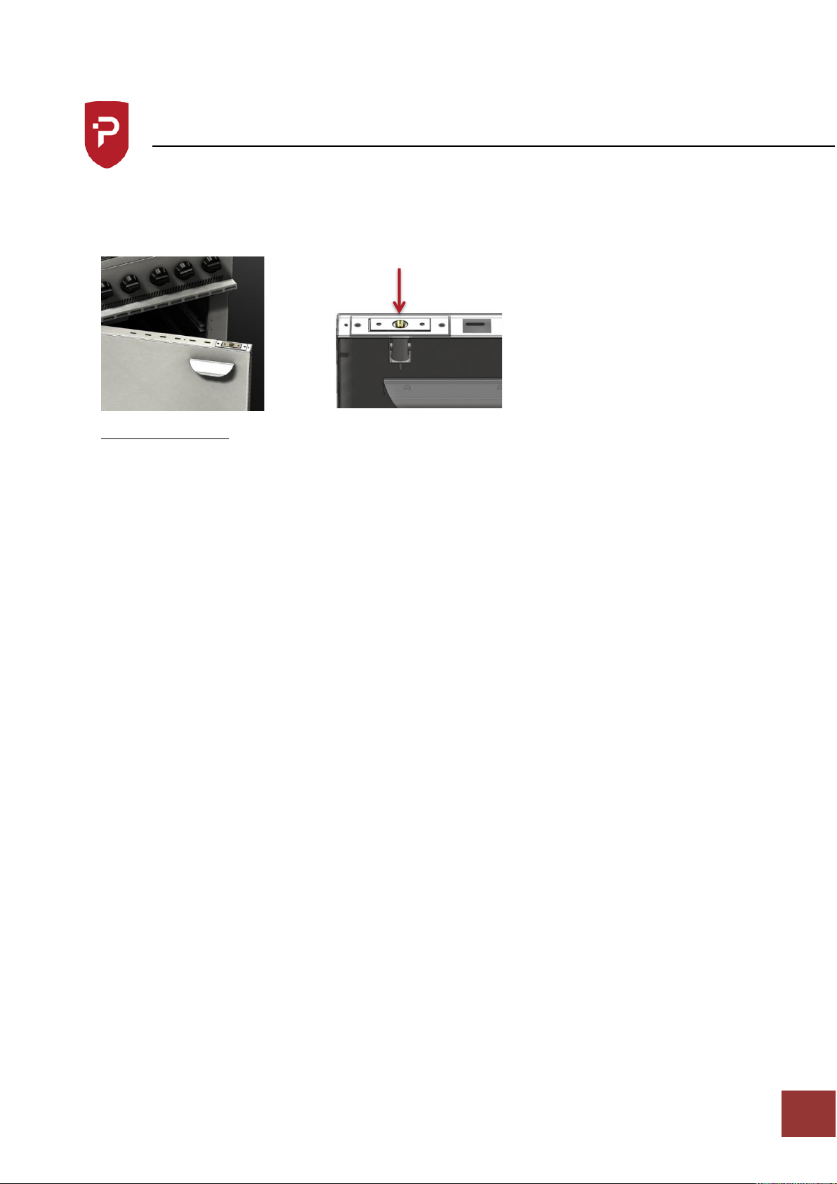
The oven doors are held shut by adjustable roller catches. When installing the appliance
ensure the catches are set to allow the door to close firmly. To adjust the catch, use a
screwdriver to press in roller to below the plate, turn clockwise to adjust downward, and
anti-clockwise to lift the roller.
GAS CONNECTION
The size of the supply pipe should be no less than 3/4” B.S.P. and an easily accessible
isolation tap fitted close to the appliance in the gas line. Although a rigid connection is
recommended. An approved armoured flexible pipe may be used in conjunction with a
straining cable.
Before the appliance is commissioned the gas, safety regulations require that all
connections on the gas line are tested for gas soundness between the gas meter and the
appliance.
All packing and protective film must be removed from panels etc. prior to commissioning
the appliance. All gas appliances must be fitted by a competent person to gas safety
regulations in force.
Gas hoses used to connect the appliance to the gas supply must be of the correct
specification for the gas and pressure of the appliance. The gas hose must comply with the
national requirements in force, and be CE marked, of a metal braided construction suitable
for commercial catering equipment.
The hoses should be periodically examined and replaced as necessary. The tube or hose
shall be fitted such that there are no sharp bends or torsional strain which may cause
damage or failure of the tube or hose, especially near the end fittings. Torsional strain can
be prevented by using internal unions, swivel joints, etc. The bend radius should not exceed
that stated by the Manufacturer. The hose should not touch the ground and should be no
longer than 1.5m long.
A manual valve should be positioned upstream of the tube or hose unless the connection
fitting incorporates a self-sealing quick release coupling.
Catch Roller
Page 8

Parry-British Built for Purpose
IN272-3
6
Installation Instructions
Where a quick release coupling is used for horizontal travel such as in commercial catering
appliances it is advisable that the coupling is facing downwards to prevent the ingress of
debris and ensure the hose is formed in to, a smooth curve. All units should have a
restraining cable fitted preventing the unit from being pulled away from the wall and
causing the gas hose to become disconnected accidentally.
Operating Instructions
Operating the hob
All burners are fitted with flame failure devices.
To light hob unit turn knob to
Press in and ignite gas with a match, keep knob held in for 15-20 seconds.
Release knob, gas should stay lit, if gas goes out then repeat stage 2.
The burner is now on full gas, to turn gas down, turn knob anti-clockwise, this is the
lowest setting, which is factory set.
To turn burners off, turn knob clockwise all the way round.
Parry recommends that the hob is used only with pans that have a minimum diameter of
120mm, and up to a maximum of 295mm diameter. This ensures that there is satisfactory
combustion, and the pan is stable as it sits on the finger of the pan support.
Operating the oven
To light oven, open doors, turn oven knob to approximate gas mark 5 and hold
tap knob in, at the same time press the piezo ignitor button on bottom of the
oven.
After pressing button 2-3 times burner should light.
Keep oven knob depressed for 15-20 seconds.
Release knob and flame should remain lit, if not repeat above sequence.
If burner goes out refer to fault finding chart.
When burner stays on oven is ready for use, select gas mark required, turn knob
to setting, oven flame will decrease when desired temperature is reached.
Please take care when opening and closing the doors of an oven that has been turned on.
Surfaces and handles will get hot. The surfaces within the oven chamber will be very hot so
it is advisable to wear oven gloves to protect from burns that may be incurred from
touching hot surfaces within the oven.
Page 9

Parry-British Built for Purpose
IN272-3
7
Operating Instructions
We advise these appliances should not be left unattended while switched on.
These appliances are for professional use by qualified people only. There are no user
serviceable parts.
There are three shelf positions in the oven, the following guide is only intended as a guide to
temperature in the centre of the oven. It is strongly recommended that the user makes note
of best results, temperatures can vary as much as 20˚c hotter at top of oven and 30˚c cooler
at the bottom of the oven.
These temperatures are measured in an empty oven.
MARK
1 2 3 4 5 6 7 8 9
˚C
130
150
170
185
203
220
240
260
280
˚F
266
300
338
365
397
428
464
500
536
Cooking Chart – the following chart is for guidance only.
USAGE
PRODUCT
GAS TEMP
HIGH TEMP.ROASTING
MEAT OR POULTRY
6 OR 7
LOW TEMP.ROASTING
MEAT OR POULTRY
3
HIGH TEMP.BAKING
BREAD OR SCONES
8
LOW TEMP. BAKING
SLAB CAKE
2
PUDDINGS
MILK PUDDING
BAKED CUSTARD
3
PASTRY
SHORT CRUST
PLATE TARTS
FLAKY
7
Page 10

Parry-British Built for Purpose
IN272-3
8
Cleaning Instructions
The appliance should be cleaned after every use.
Allow unit to cool down before cleaning
Wipe down the machine with warm soapy water using a soft cloth, do not use abrasive
materials.
The two wire shelves and bottom vitreous enamelled bottom tray can be removed for
cleaning, the bottom tray must be in position when the appliance is in use, however.
Stainless steel cleaners maybe used and cleaning instructions on the product must be
adhered to.
Never clean the unit with water jets.
Page 11
Parry-British Built for Purpose
IN272-3
9
Maintenance Instructions
Ensure the appliance is isolated from the power supply before installing, cleaning or
maintaining the appliance.
Maintenance and service must only be undertaken by a qualified electrician.
Parry Catering provides a complete after-sales service by offering the sales of spare parts
directly to customers. Buying spares straight from the manufacturer allows customer to
experience exceptional value and speedy delivery on all spare parts.
For more information on buying spares visit:
www.parry.co.uk/parry-commercial-catering-spares
PLEASE NOTE THE LOW RATE ADJUSTER ON THE UNIT HAS BEEN FACTORY SET AND
SHOULD NOT BE ADJUSTED UNLESS BY A QUALIFIED ENGINEER IN WHICH CASE THE LOW
RATE ADJUSTER SHOULD BE RE-SEALED.
Parry recommends that this unit is serviced at least every 6 months
As part of a full service we recommend the following checks are carried out.
Before any maintenance isolate the appliance from the gas supply
Examine and clean all burner and flame retention ports.
Using a combination of brushes, remove dust and lint from within the primary air
ports venture and burners. Check the burner aeration to ensure it is clear of
debris.
Clean burner injectors ensuring orifices are not enlarged or damaged.
Stiff gas controls can in some instances be greased. Please ensure the correct
type or grease is used.
Check any ignition electrodes and high tension leads where fitted. Clean and
adjust where necessary.
Check Door seal for damage and condition.
Reconnect gas supply and test all disturbed gas connections for gas tightness
using a non-corrosive leak detection fluid.
Check the appliance burner operating pressure, heat input rating or where
necessary both.
Page 12
Parry-British Built for Purpose
IN272-3
10
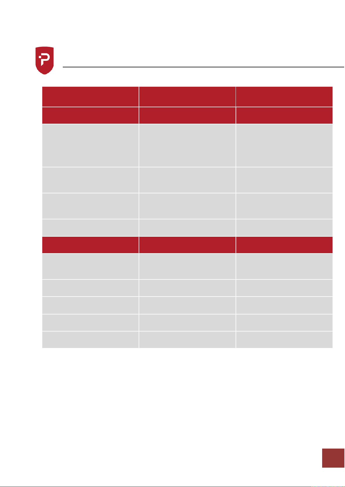
Fault Finding
Fault
Check
Solution
HOB
Incorrect flame picture, flame
lift or noisy burner
Incorrect burner pressure,
Blocked or partially blocked
injector.
Inadequate ventilation.
Burner faulty/corroded/blocked
Check/adjust burner pressure
Check /clean injector,
Check ventilation.
Check / clean burner and
replace as necessary.
Burners will not stay alight
Faulty connection at
thermocouple-valve, incorrectly
located
Remake connection, reposition
thermocouple
Burner goes out when turned
to “low”
Blockage in tap
Clean and re-grease
Irregular flame
Burner ring/cap not correctly
located, or low pressure
Relocate and check pressure at
test point.
OVEN
Failure to ignite
Dirt or grease broken or loose
connection
Clean reconnect / replace H.T.
Lead
Incorrect spark gap
Set gap 3-4mm
Burner fails on low rate
Loose Thermocouple
Replace
Faulty Magnet in F.F.D.
Replace thermostat
Burner fails on low rate
Thermocouple out of position.
Reposition
Page 13

Parry-British Built for Purpose
IN272-3
11
Replacement Parts
For Gas Safe Engineers only
HOB TAP- Remove pan supports, pull off control knobs and unclip fascia panel.
Disconnect burner supply tube and thermocouple. Undo the 2 screws securing the tap to
the rail. Check sealing washer and replace if necessary. Assemble in reverse order.
HOB BURNER/THERMOCOUPLE – Remove Pan Supports and Burner caps. Remove the solid
top tray.
Disconnect thermocouple from rear of tap. Undo locknut on burner mounting channel.
Assemble in reverse order.
OVEN THERMOSTAT - Proceed as for hob tap. Slide thermostat phial from housing inside
oven. Remove through hole in the top of the oven on right hand side. Assemble in reverse
order.
OVEN THERMOCOUPLE - Remove the bottom oven tray. Inside the oven disconnect the
thermocouple from the extension piece. Undo locknut holding thermocouple to oven
burner. Assemble in reverse order. Ensure locknut is securely tightened.
OVEN BURNER/IGNITON - Remove oven base. Disconnect oven supply tube, H.T. lead and
thermocouple. Burner is held in by 2 screws. Piezo spark generator is secured by a locknut.
Electrode secured to burner bracket by centre screw.
Page 14

Parry-British Built for Purpose
IN272-3
12
Natural Gas – Conversion Instructions
Product
GB4P – Gas 4 Burner Cooker LPG
For use with models with the following serial numbers
Model
From
To
GB4
These instructions can be used for converting from LPG to Natural Gas
LPG units are designed and tested in accordance with all current regulations enforced to run
on the following gases only
Nat Gas G20 @ 20mbar 8” W.G.
PLEASE NOTE
This conversion must be carried out by a Gas Safe Registered Engineer.
This conversion kit includes
Description
Product Code
Quantity
Hob valve bypass
screw
NAT GAS Hob valve bypass screw
stamped with 85
COPBPS - 85
4
Hob burner
injector
NAT GAS Hob Burner Injector
stamped with 185
HOBINJECT185
4
Oven valve
bypass screw
NAT GAS Oven valve bypass
screw stamped with 60
COPBPS - 60
1
Oven burner
injector
NAT GAS oven burner injector
stamped with 150
INJECT150
1
Labels
NAT. GAS ONLY
1
Instructions
CONVIN34-4
1
Page 15

Parry-British Built for Purpose
IN272-3
13
LPG Gas – Conversion Instructions
Product
GB4 – Gas 4 Burner Cooker
For use with models with the following serial numbers
Model
From
To
GB4
These instructions can be used for converting from Natural Gas to LPG
LPG units are designed and tested in accordance with all current regulations enforced to run on
the following gases only
Propane G31 @ 37mbar 14.8” W.G.
PLEASE NOTE
This conversion must be carried out by a Gas Safe Registered Engineer.
This conversion kit includes
Description
Product Code
Quantity
Hob valve bypass
screw
LPG hob valve bypass screw
stamped 50
COPBPS-50
4
Hob burner
injector
LPG hob burner injector stamped
105
HOBINJECT105
4
LPG oven valve bypass screw
stamped 40
COPBPS-40
1
LPG oven burner injector
stamped 0.99
INJECT099
1
Labels
G31 ONLY,
1
Instructions
CONVIN35-4
1
Page 16
Parry-British Built for Purpose
IN272-3
14
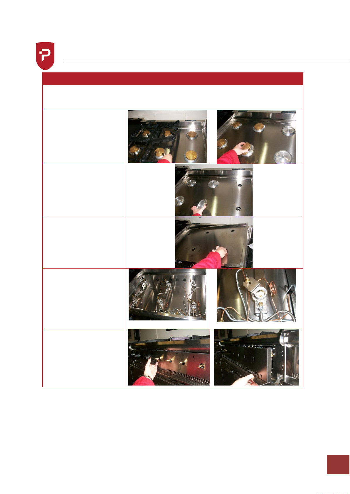
Conversion Procedure
Conversion Procedure for GB4
Warning
Ensure the appliance is isolated from the gas supply before commencing conversion
(Please note GB4 only has four hob burners)
Remove pan support and
burner caps.
Lift off aluminium burner
plates.
Remove the solid top
plate.
Using an 10mm spanner
remove burner injector.
Replace with injector
from conversion kit.
Replace solid top plate,
aluminium burner plates
and burner caps.
Remove the tap knobs to
allow the fascia to unclip.
Page 17
Parry-British Built for Purpose
IN272-3
15
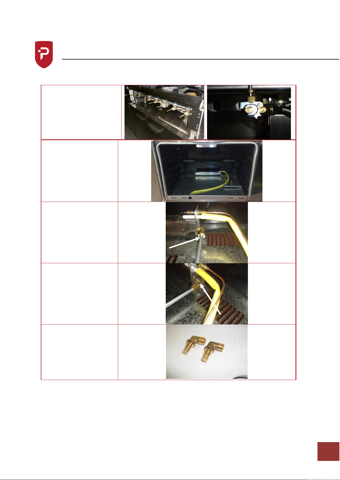
Conversion Procedure
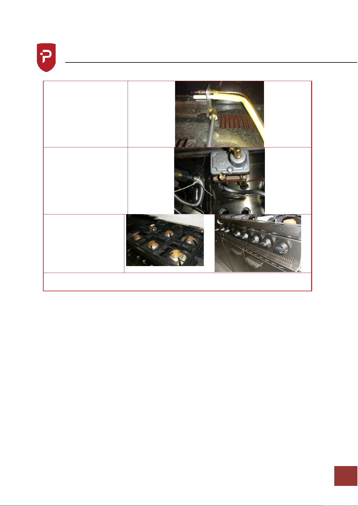
Remove low rate screws
in tap body and replace
with low rate screw from
the conversion kit.
Converting the oven
burner
Unscrew the 15mm nut
on the jet that goes into
the burner
Unwind the jet out of the
burner
Replace jet with the jet
for the required gas
Page 18
Parry-British Built for Purpose
IN272-3
16
Conversion Procedure
Tighten up the 15mm nut
Unwind the bypass screw
on the oven valve and
replace with the bypass
screw for the required gas
Connect the unit back to
the gas supply
Test for gas soundness
Replace the facia and
knobs accordingly
When comversion is complete add new data label and gas type label supplied with the
conversion kit, detailing type of gas and pressure.
Page 19

Parry-British Built for Purpose
IN272-3
17
Technical Information
Per Hob Burner
GAS
OPERATING PRESSURE
TOTAL HEAT INPUT
NATURAL G20
20mb / 8” W.G.
5.557 KW = 18959 Btu/h
PROPANE G31
37mb / 14.8” W.G.
4.351 KW = 14846 Btu/h
GAS RATE
M³/HR
FT³/HR
LB/HR
KG/HR
NATURAL G20
0.588 M³/HR
20.765 FT³/HR
PROPANE G31
0.178 M³/HR
6.286 FT³/HR
0.691 LB/HR
0.313 KG/HR
BURNER LOW RATE
FLOWRATE
HEAT INPUT
NATURAL G20
0.126 M³/HR
1.176 KW
PROPANE G31
0.029 M³/HR
0.700 KW
Per Oven Burner
GAS
OPERATING PRESSURE
TOTAL HEAT INPUT
NATURAL G20
20mb / 8” W.G.
6.804 kW = 11962 Btu/h
PROPANE G31
37mb / 14.8” W.G.
8.140 kW = 11927 Btu/h
GAS RATE
M³/HR
FT³/HR
LB/HR
KG/HR
NATURAL G20
0.720 M³/HR
13.102 FT³/HR
PROPANE G31
0.333 M³/HR
5.050 FT³/HR
0.555 LB/HR
0.632 KG/HR
Total Unit
GAS
OPERATING PRESSURE
TOTAL HEAT INPUT
NATURAL G20
20mb / 8” W.G.
29.032 kW = 99148 Btu/h
PROPANE G31
37mb / 14.8” W.G.
25.544 kW = 83571 Btu/h
GAS RATE
M³/HR
FT³/HR
LB/HR
KG/HR
NATURAL G20
3.075 M³/HR
108.593 FT³/HR
PROPANE G31
1.045 M³/HR
35.385 FT³/HR
3.889 LB/HR
1.984 KG/HR
AIR FLOW RATE FOR COMBUSTION
20m³/HR
32.18FT³/HR
Page 20

Parry-British Built for Purpose
IN272-3
18
Service Information
This appliance should be routinely serviced to prolong its lifetime. Parry recommends that
the appliance is serviced every 12 months by a Parry authorised engineer. Failure to service
your product within the initial 12 month warranty period will cause the 24 month warranty
to become void.
If the supply cord becomes damaged, it must be replaced by the manufacturer, it’s service
agent, or a similarly qualified person.
Enhanced 2 Years Warranty
Parry Catering (Midlands) Ltd offer an enhanced warranty of two
years (including parts and labour) on all of the Parry manufactured
products. To take advantage of this you should register you warranty
by logging onto the company website and filling out our simple form.
www.parry.co.uk/the-parry-warranty
If you have any issues with your product and wish to request a
warranty call you can contact our friendly team who will organize a
Parry approved service engineer to attend and fix your problem.
All warranty requests can be sent to [email protected]
alternatively call our warranty department for technical assistance on
01332 875544
Page 21
Parry-British Built for Purpose
IN272-3
19
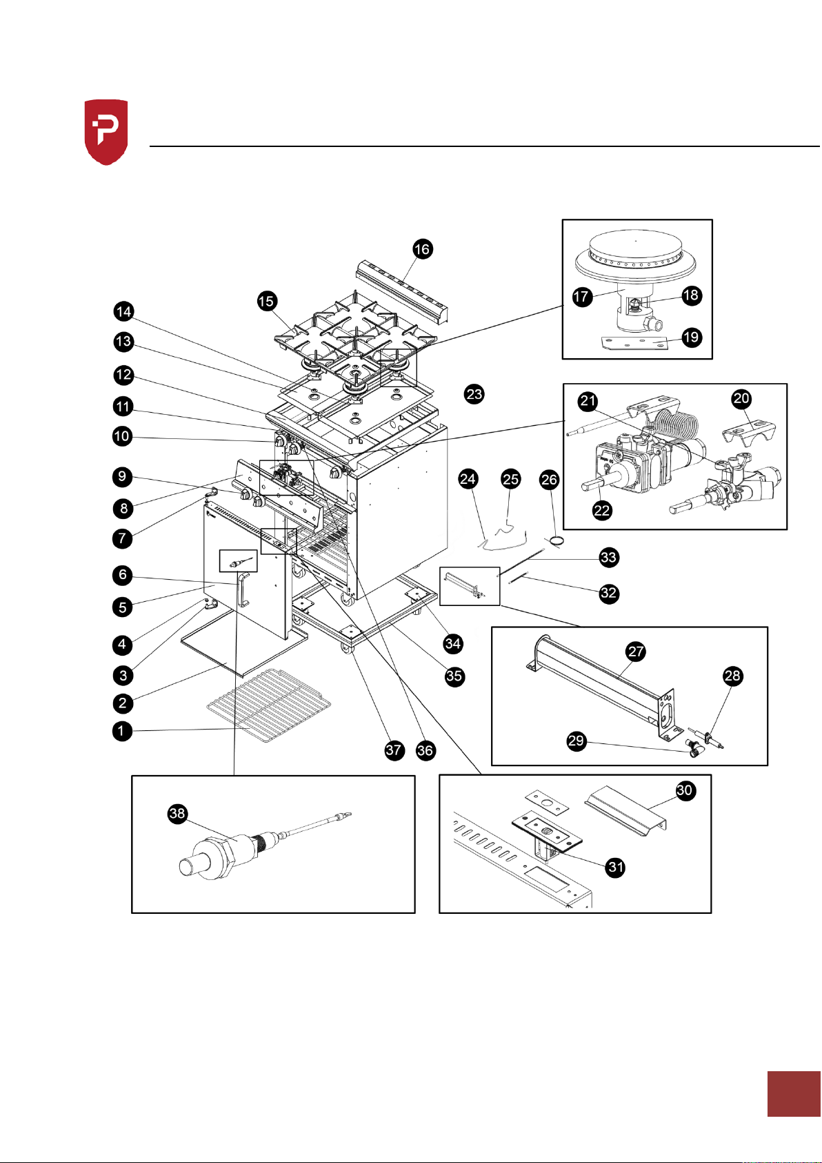
Exploded View
Page 22

Parry-British Built for Purpose
IN272-3
20
Parts List
Part Number
Description
Code
1
Shelf
TRWC00750
2
*Tray
*No Code
3
Bottom Hinge
ULT6BOHINGEBL
4
Hinge Bush
ULTHINGEBUSH
5
Door
6
Door Handle
GB6HANDLE
7
Top Hinge
ULT6BOHINGETL
8
*Fascia
*No Code
9
Control Knob Hob
ULTKNOB5A
10
Control Knob Oven
ULTKNOB4A
11
Gas Rail
GB6GASRAIL
12
*Top Surround
*No Code
13
*Top Left Cover
*No Code
14
*Top Right cover
*No Code
15
Pan Support
CASTP6BO
16
*Flue Cover
*No Code
17
Hob Burner Complete with Injector
Carriage
BURNRHOB
18
Hob Injector (Nat)
Hob Injector (LPG)
HOBINJECT185
HOBINJECT105
19
*Injector Carriage Plate
*No Code
20
Saddle Bracket
SADDLEBKT
21
Hob Gas Valve
GASTAPHOB
21a
Hob Bypass Screw (Nat)
Hob Bypass Screw (LPG)
COPBPS-70
COPBPS-50
22
Oven Valve
OVENVALVE
22a
Oven Bypass Screw (Nat)
Oven Bypass Screw (LPG)
COPBPS-85
COPBPS-50
23
*Thermocouple Bracket
*No Code
Page 23

Parry-British Built for Purpose
IN272-3
21
Parts List
Part Number
Description
Code
24
600mm Thermocouple
THCP600ISP
25
320mm Thermocouple
THCP320ISP
25a
Thermocouple Extension Lead
THERMCOUPEXT
26
1830mm HT Lead
CABLHT1830
26a
High Temperature Sleeving (Length
mm)
SBSY00GAS
27
Oven Burner
BURNROVEN
28
Electrode
ELECT7013
29
Oven Injector (Nat)
Oven Injector (LPG)
INJECT220
INJECT150
30
Door Keep
LCPDOORKEEP
31
Ball Catch Assembly
32
Flexi Tube 200mm
FLEXT200X8
33
Flexi Tube 500mm
FLEXT500X8
34
75mm Swivel Castor
CASTOR75SW
35
*Chassis
*No Code
35a
Leg Plate
LEGPLATE
36
Oven Gas Pipe
OVENPIPE1
37
75mm Swivel Braked Castor
CASTOR75BR
48
Piezo + Link Lead
GB6PPIEZO
Adjuster Boss for Castors
ADJM12
Door Seal
SEALPGS10
Door Seal Dart Clips (18 Per unit)
CLIP01180
Flue Joining Gasket
GASK07013
Oven Insulation Set
RKWL07013
*Metalwork Components
Page 24

Parry-British Built for Purpose
IN272-3
22
Warranty Information
Not covered under warranty
Fault due to incorrect installation, poor maintenance
or equipment abuse.
Resetting of equipment or circuit breakers.
Faulty electrics – e.g. customer’s plug socket, plug,
wiring, junction box fault, wrong fuse.
Products must be serviced within the first 12
months to be eligible for the 2 year warranty
Product not covered by warranty if combustible
materials have been used, e.g. plastic trays.
Foil used on racks, blockages and lime scale issues.
Failure to grant access for pre-arranged service
call.
Equipment that has been set up or used incorrectly
e.g. dishwasher detergents, levelling and setting up
of doors on a six burner cooker.
Excessive carbon build-up on griddle plates or
overuse of lava rock on chargrills. (Recommended
use by Parry no more than 2kg.)
All of the above points are not covered by
warranty and any costs incurred, because of the
above, will be forwarded to the parties responsible
for placing the call.
The manufacturer’s warranty is only valid in the UK
mainland. Northern Ireland, Western Isles, Inner
Hebrides and Islands are parts only warranty. Please
be aware that the warranty starts from the date of
purchase from Parry and not the sale or installation
date of the equipment.
To be eligible for a 2 year warranty, products must be
serviced at least once within the first 12 months of
purchase.
All service calls will be carried out between 8am
and 5pm, Monday to Friday.
Your warranty is invalid if your equipment has not
been installed in accordance with the
manufacturer’s instructions. The misuse, alteration
or unauthorised repairs of the equipment will also
invalidate the warranty.
During the warranty period it is at Parry’s
discretion whether to repair or replace the
equipment.
The warranty only applies if the equipment has
been used in a professional manner following the
manufacturer’s instructions and maintenance
guidelines.
The warranty covers defects in the material and
component failure only. We are not liable for trading
loss, loss of perishable items, water damage or loss
due to injury or fire damage.
Please ensure you have referred to the
manufacturer’s instruction before placing a warranty
call.
Contact our warranty department on 01332 875544
for technical assistance.
Please have your model number ready before calling.
All warranty requests must be submitted to
Failure to pay any warranty charges will result in your
warranty being put on hold until the bill has been
settled. Any issues regarding the raised charges should
be put in writing to our warranty department for
further investigation.
Register your product by visiting our website
www.parry.co.uk
Page 25

Parry-British Built for Purpose
IN272-3
23
Disposal & Recycling
The packaging should be disposed of in accordance with the regulations in force.
 Loading...